


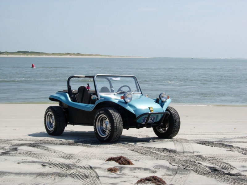
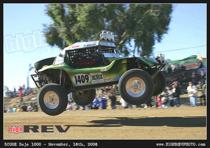


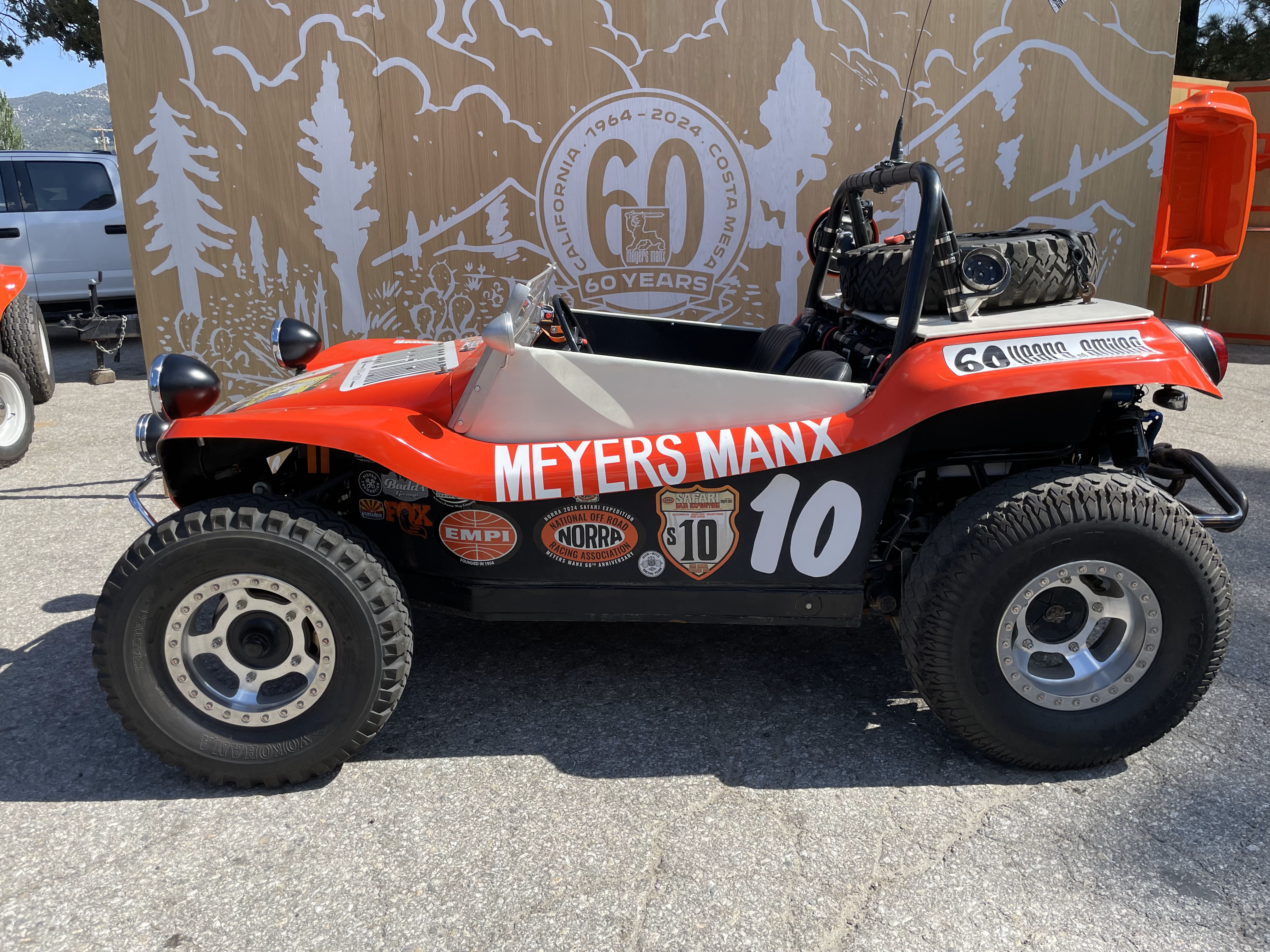


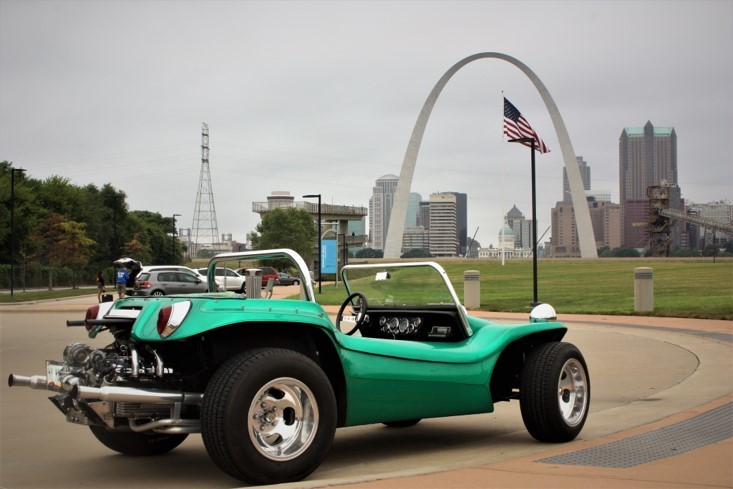
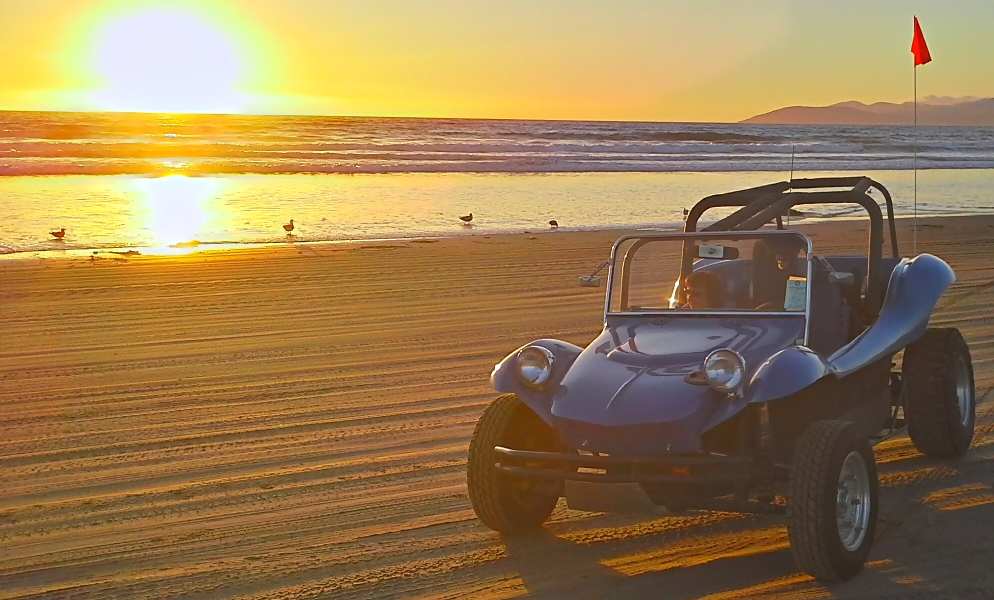


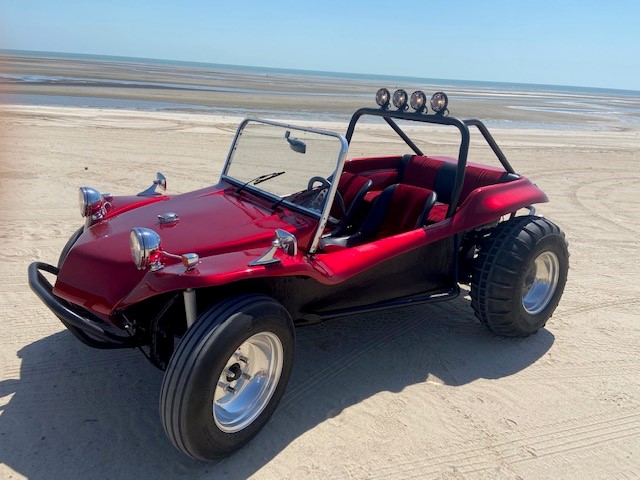


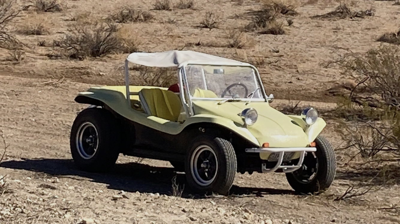
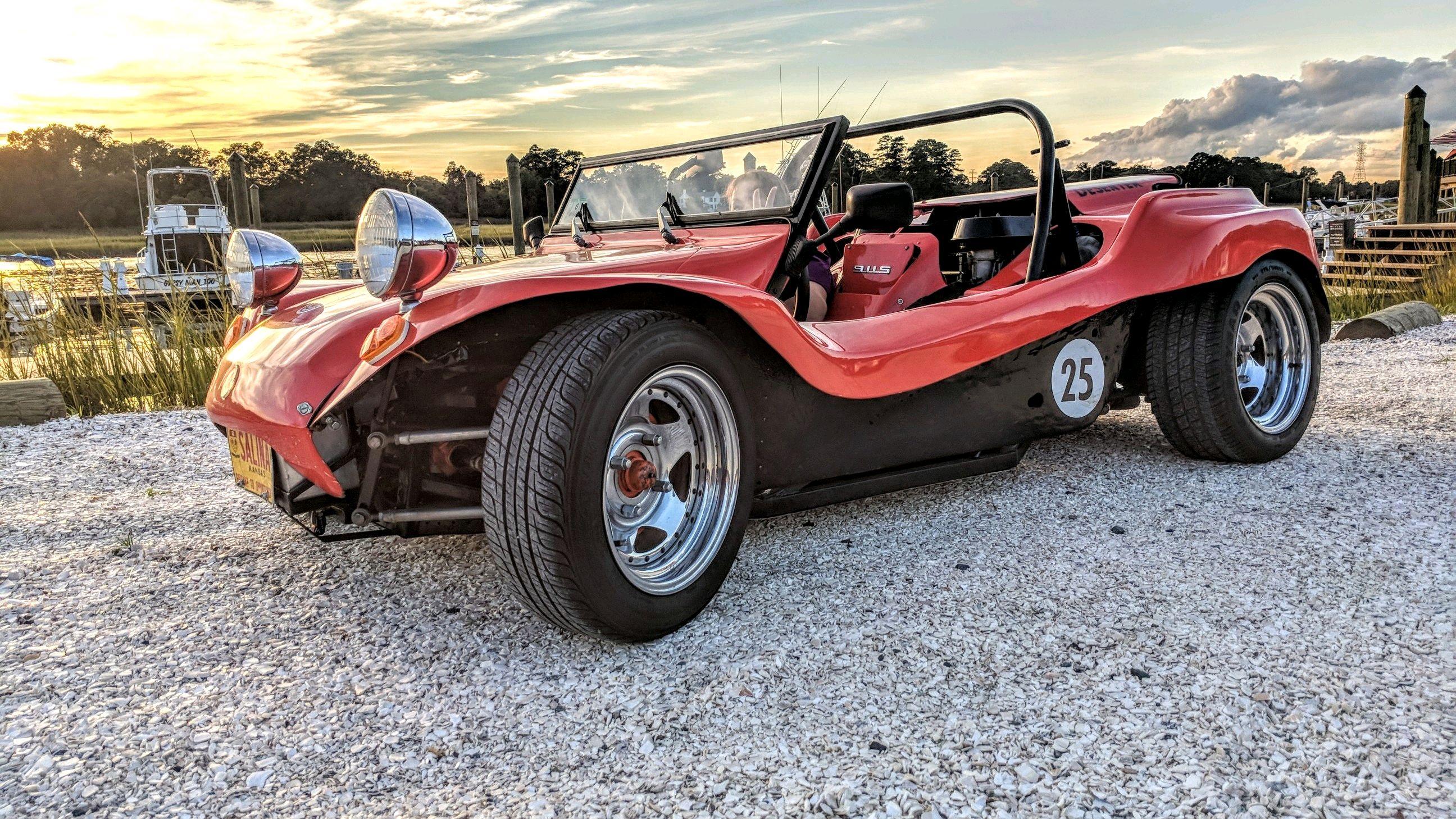
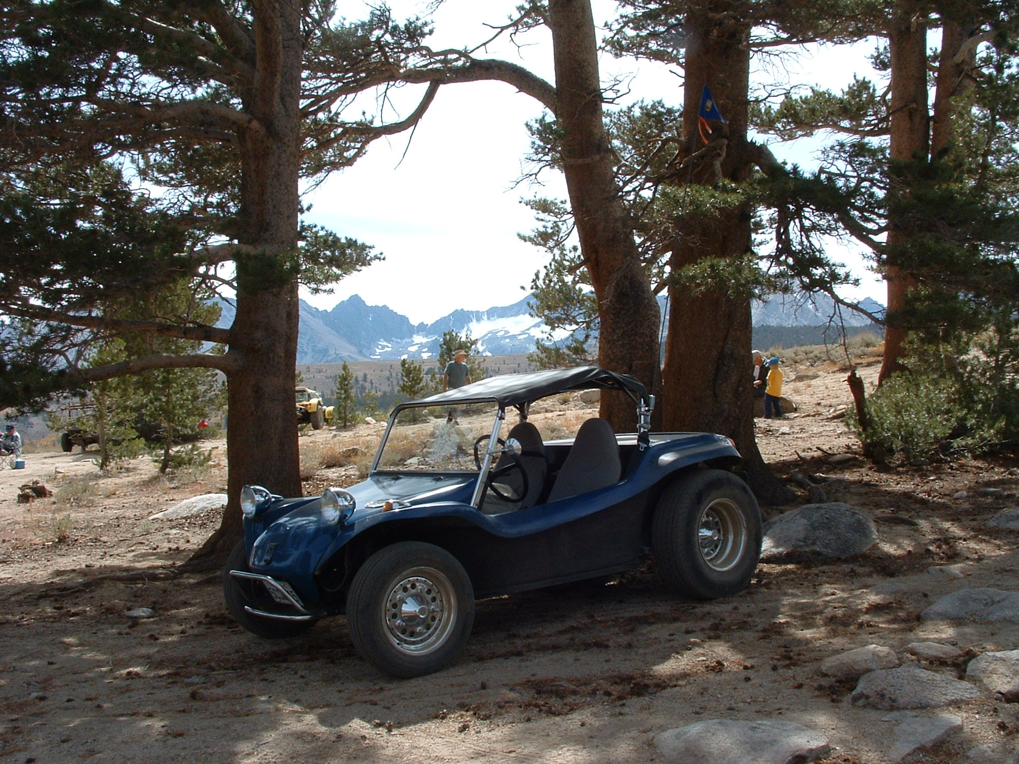


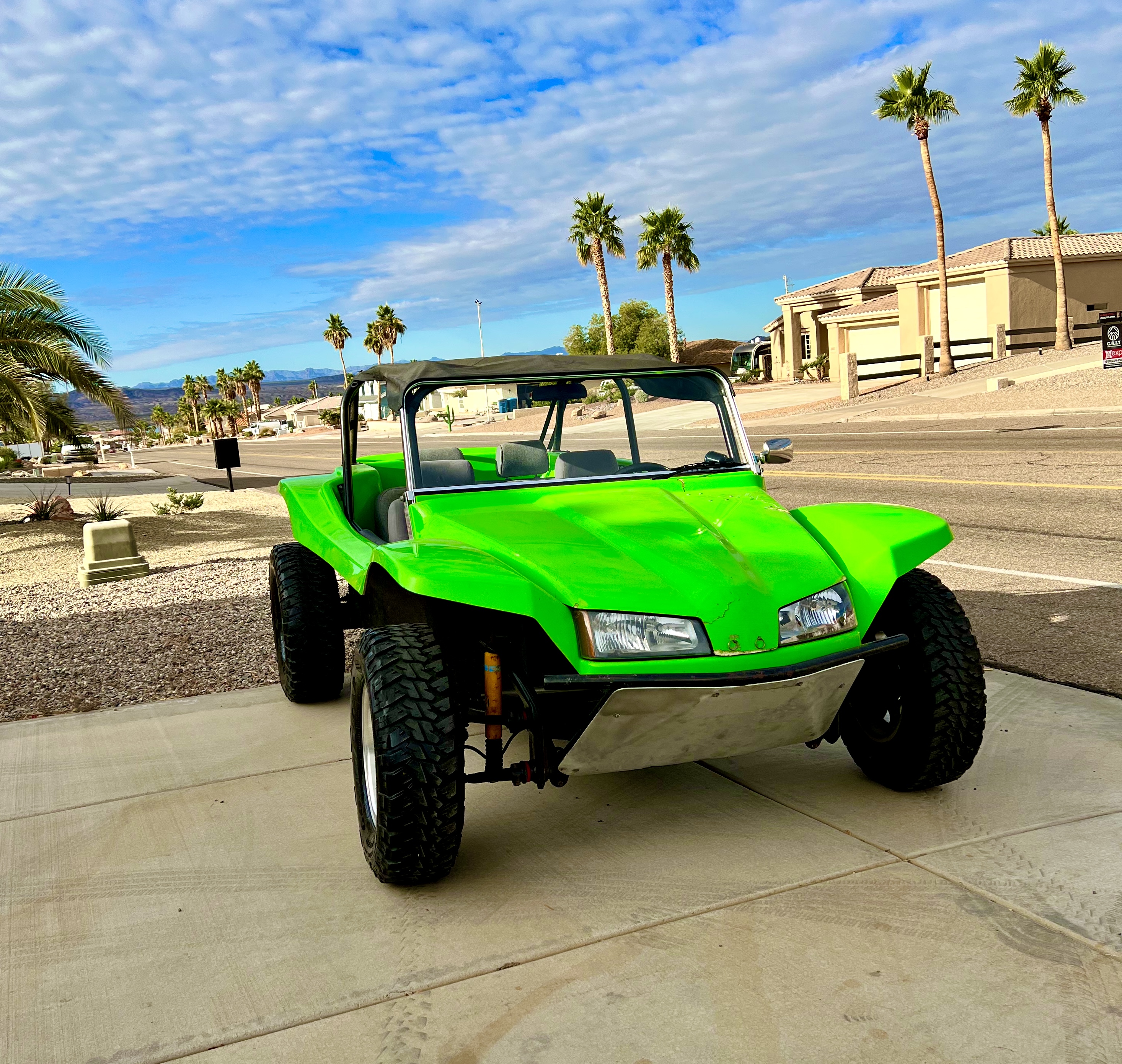
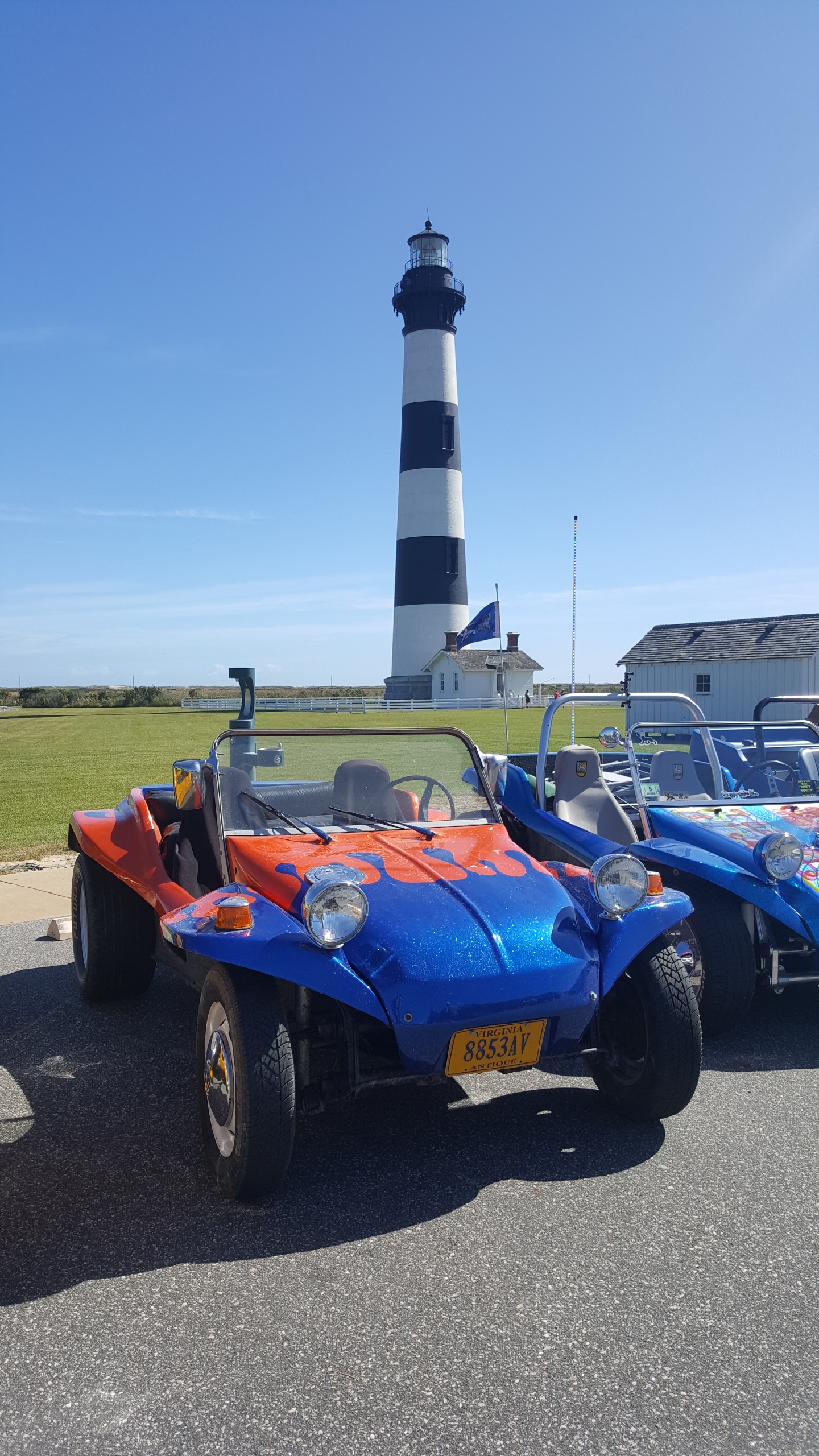


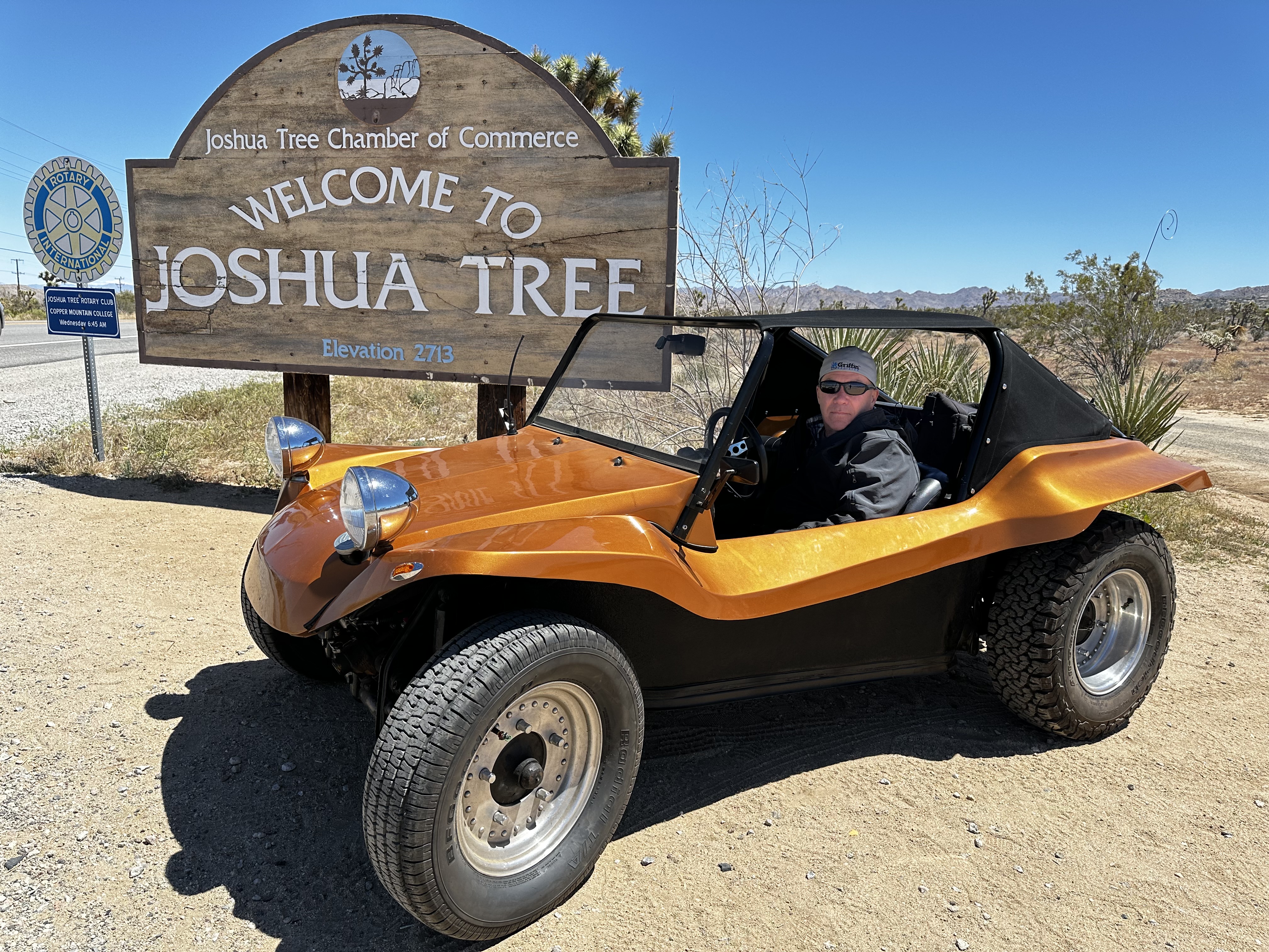

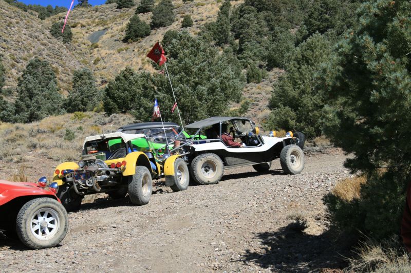


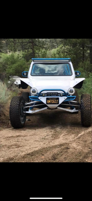


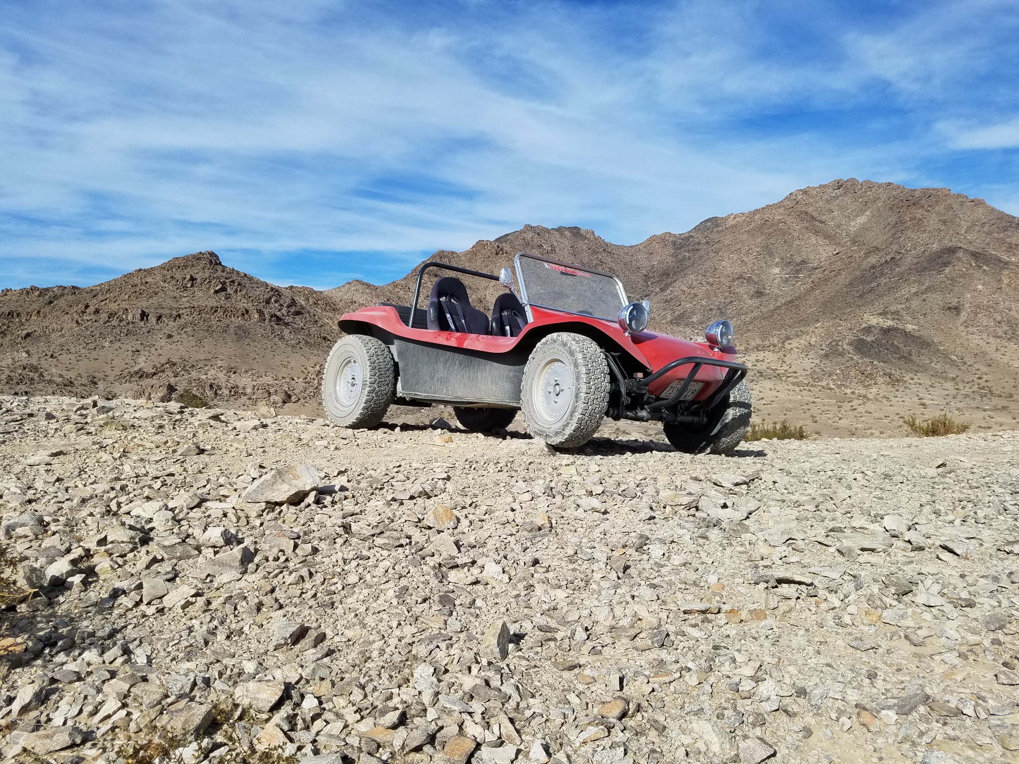


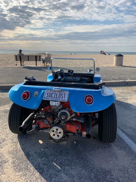


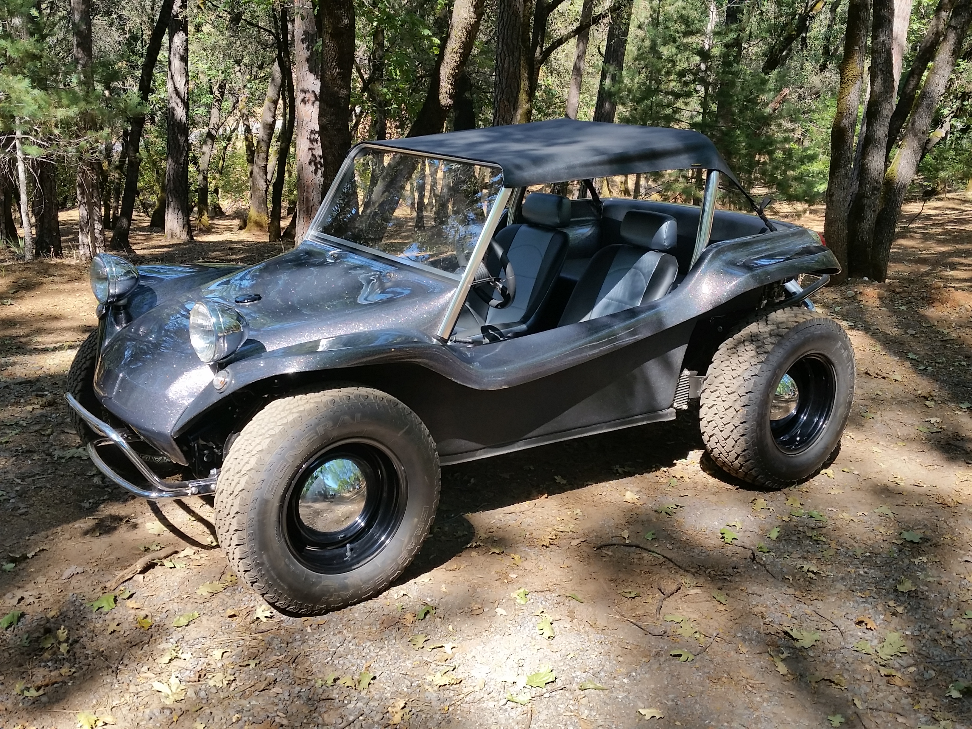


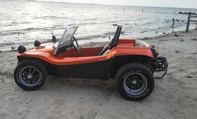


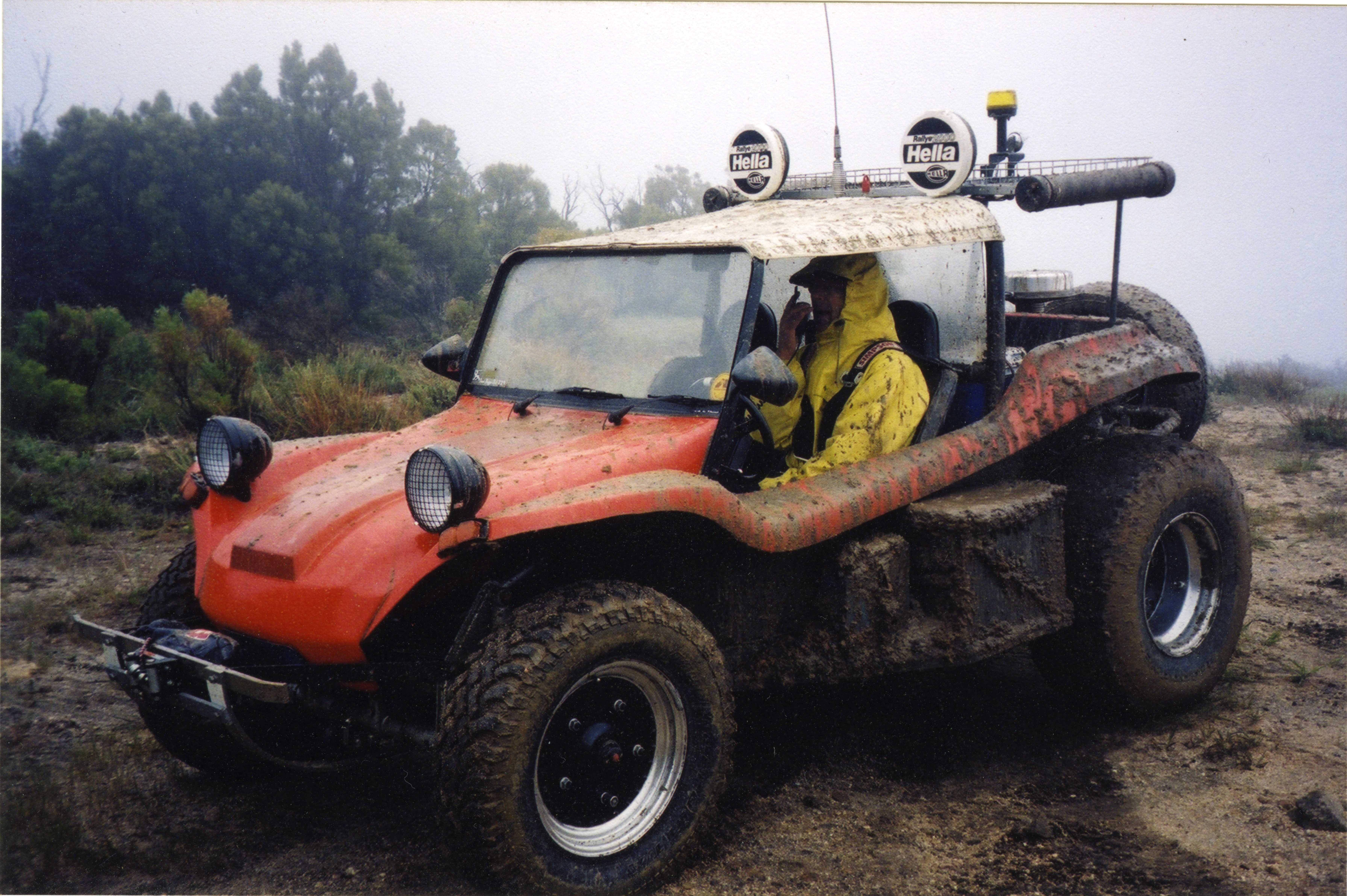


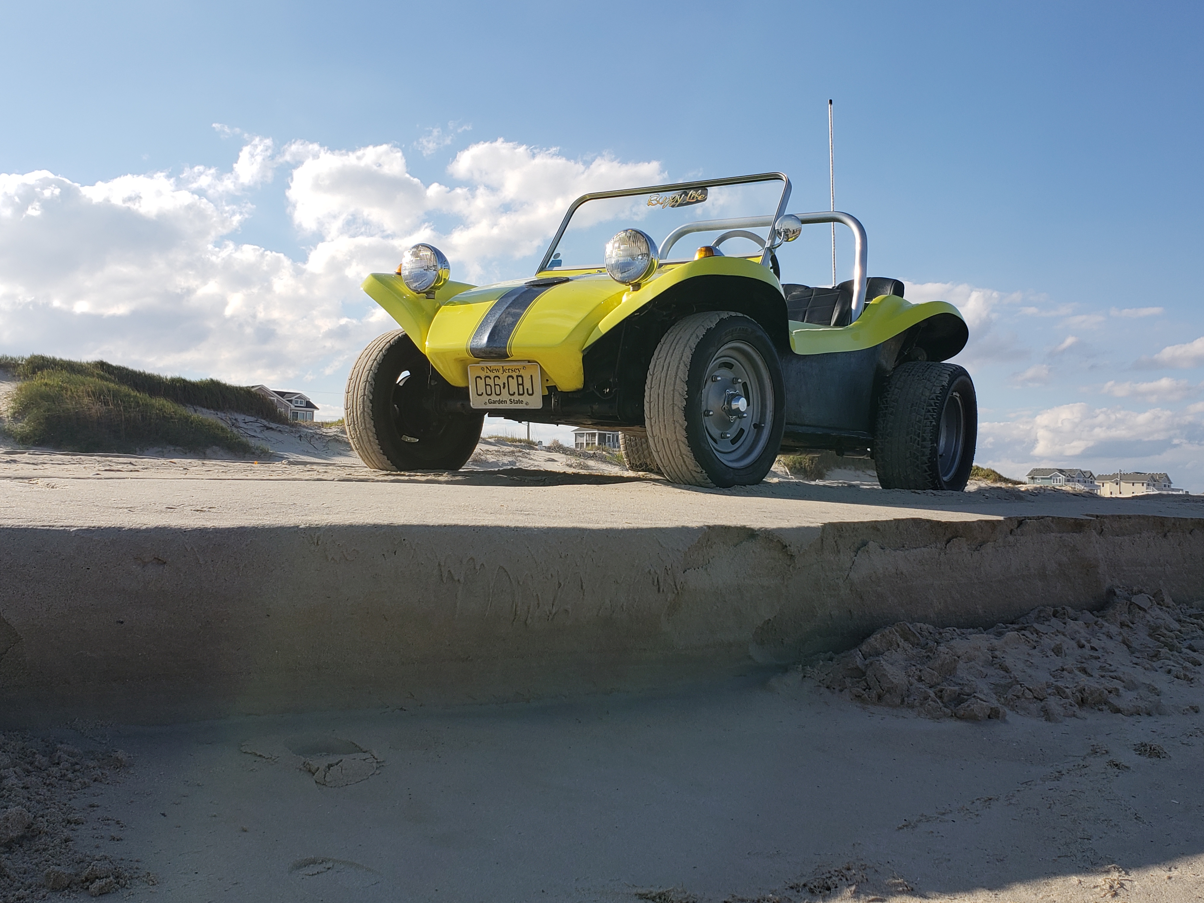

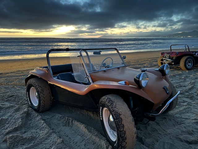
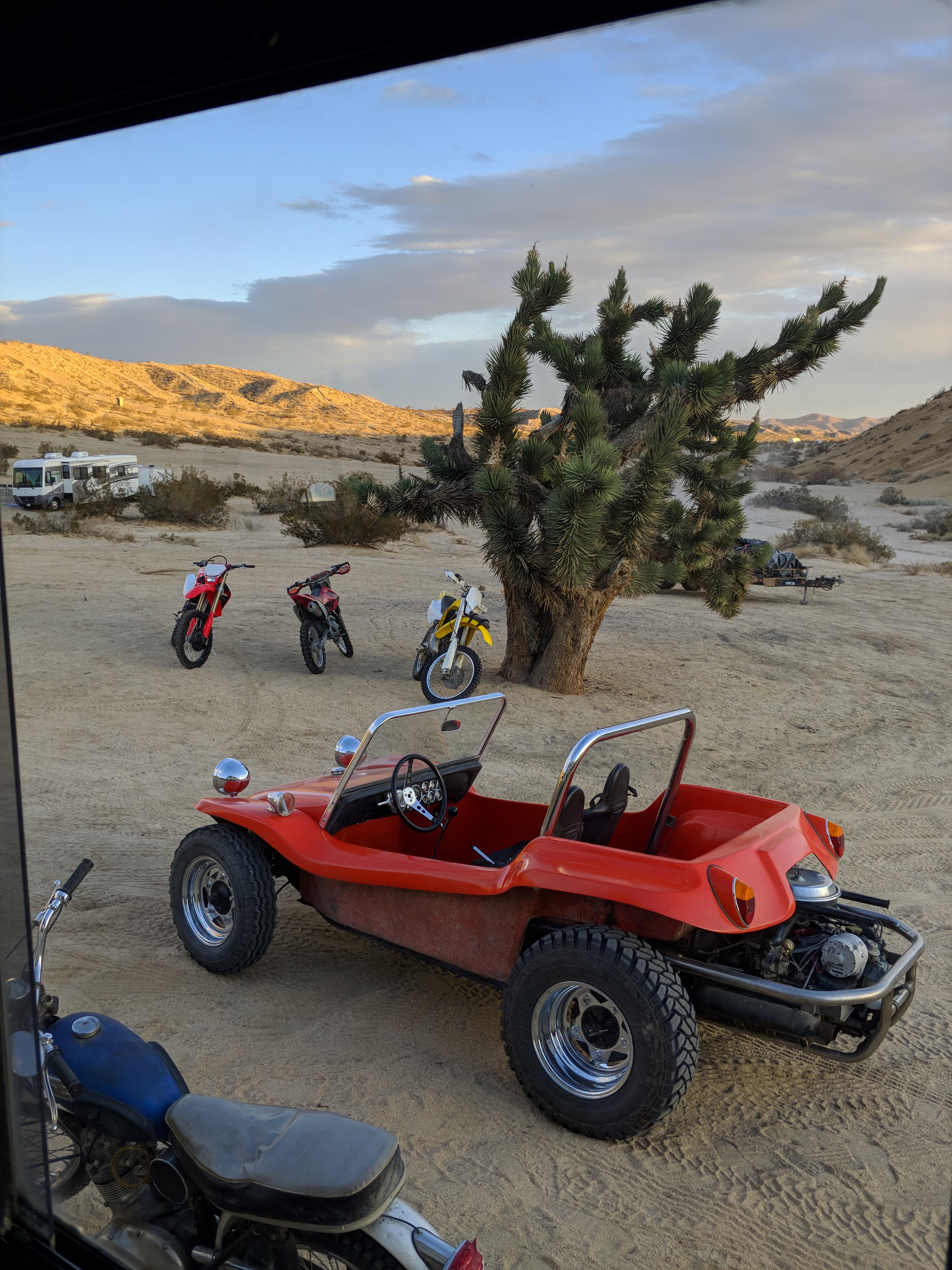


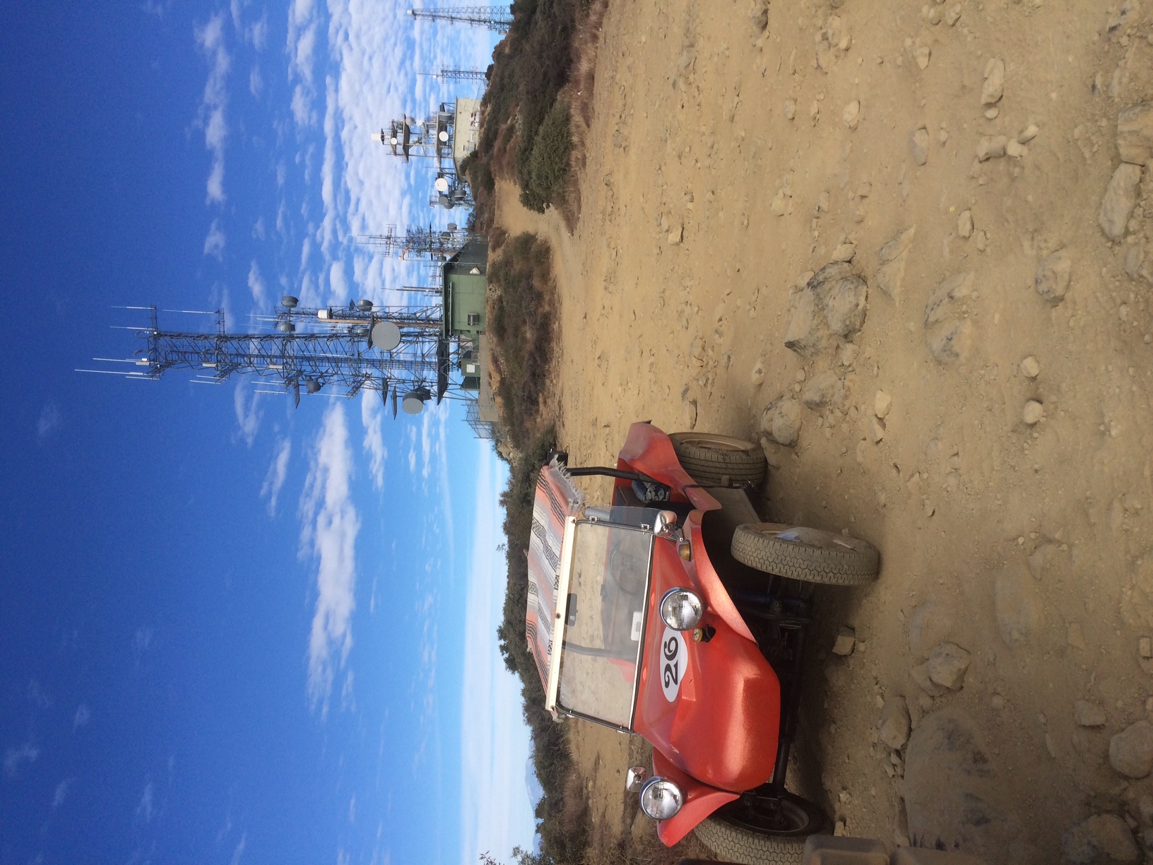
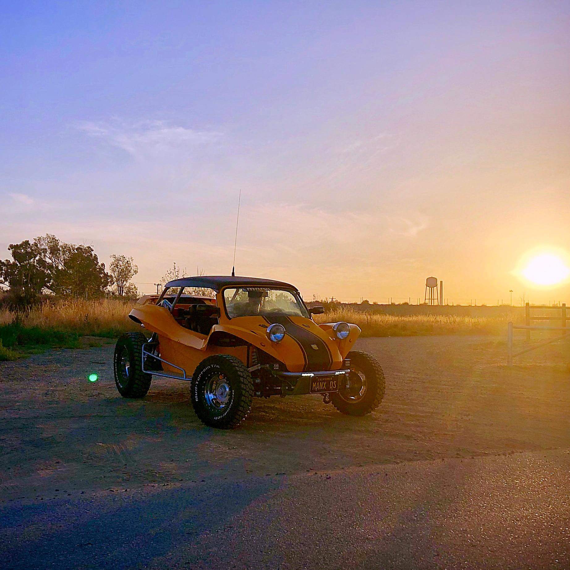


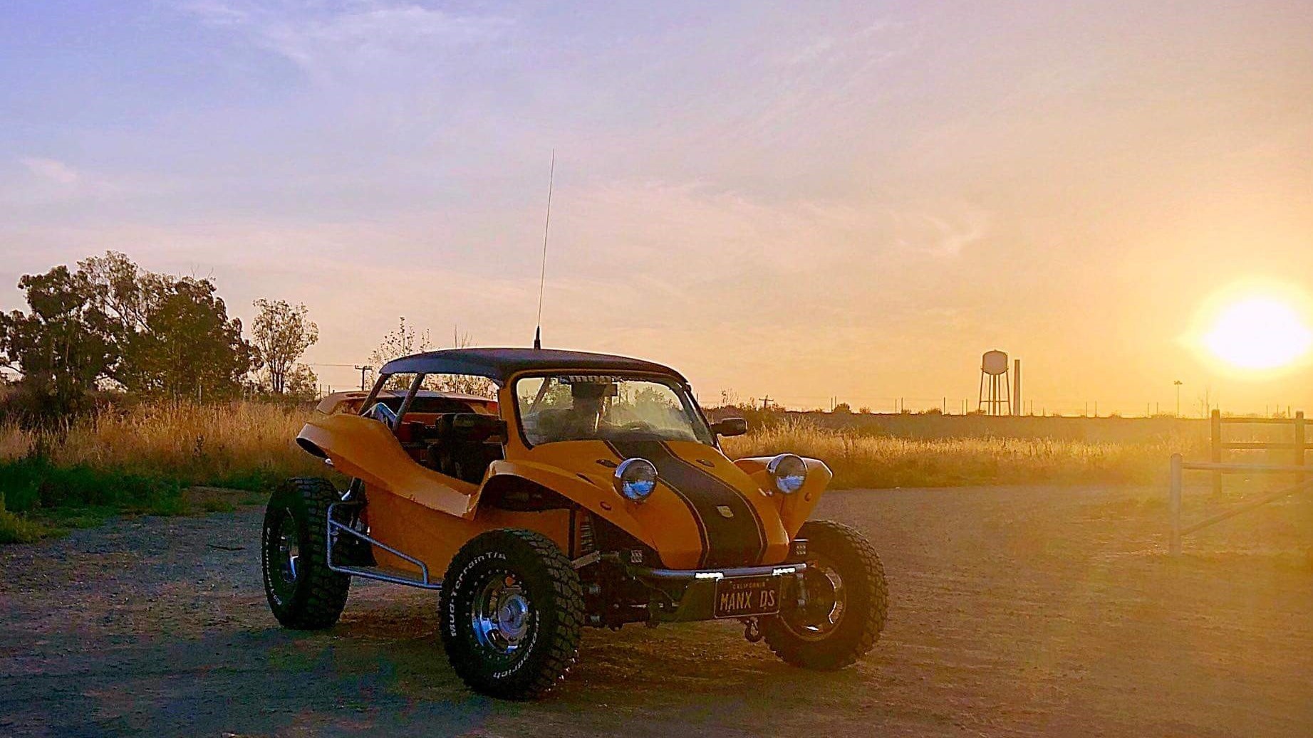


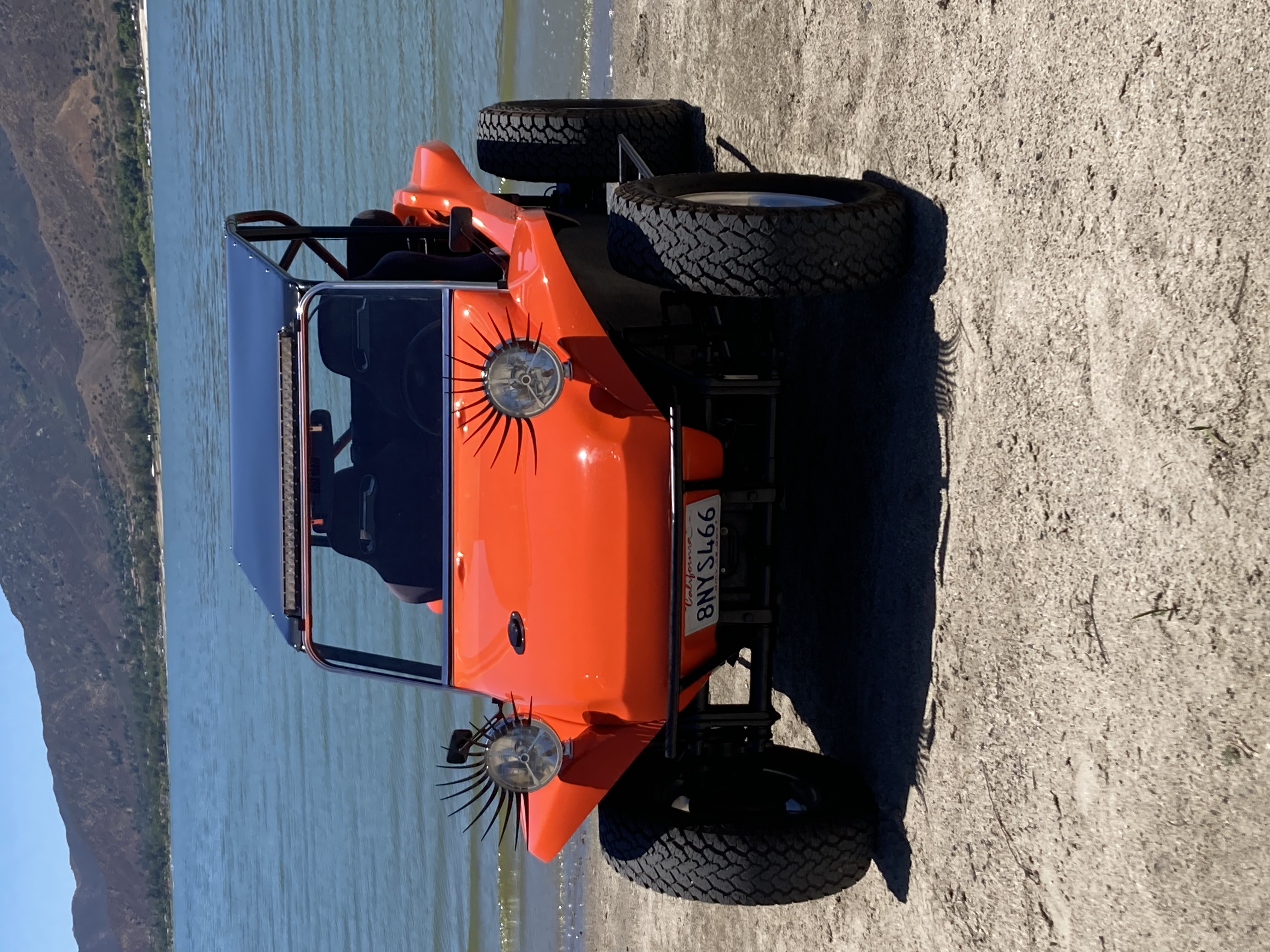


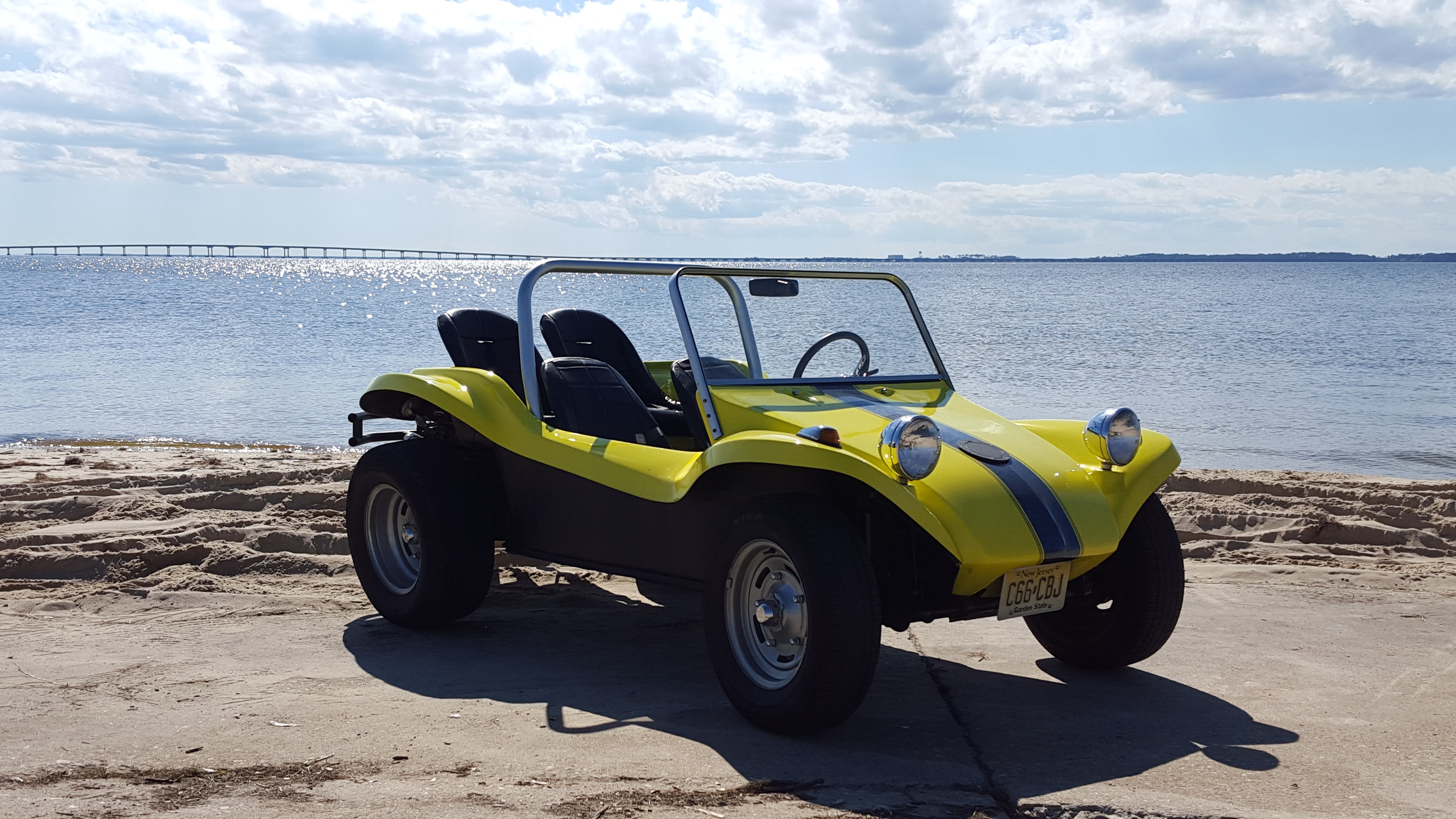

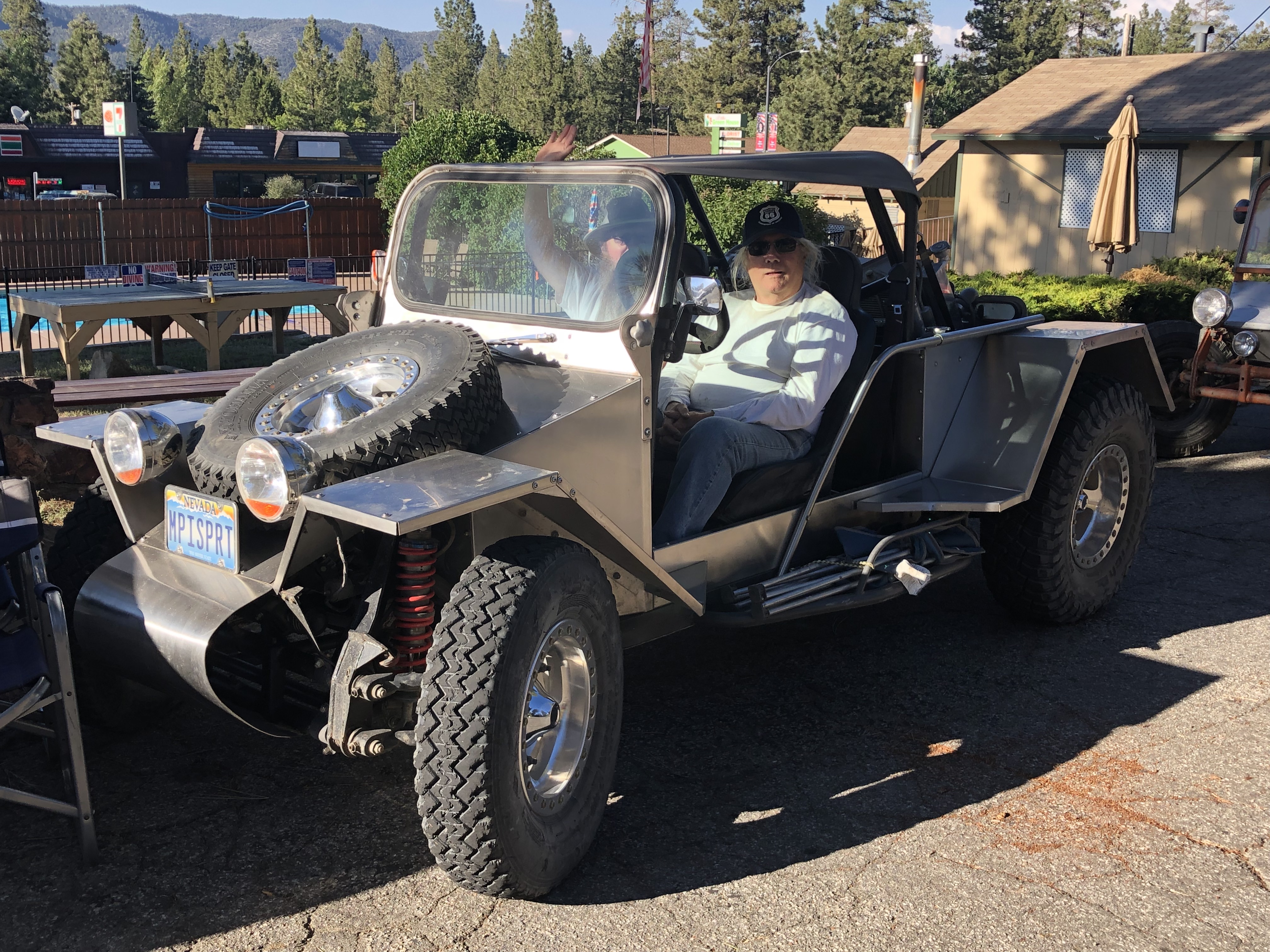
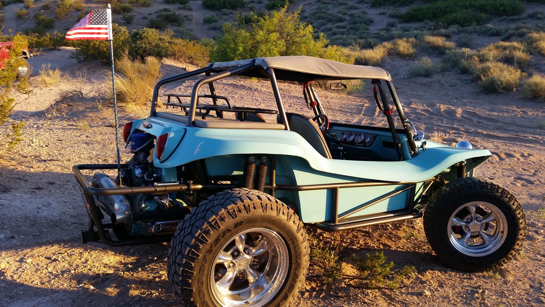
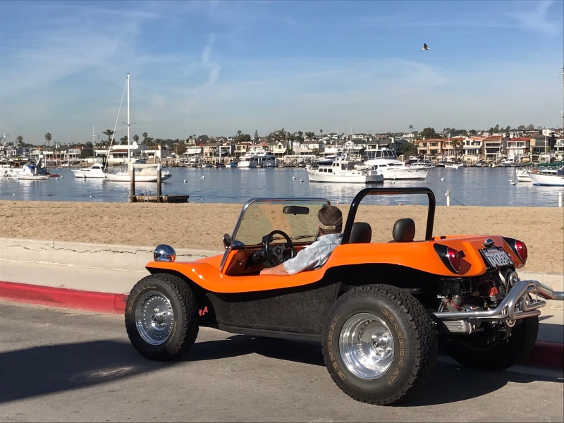
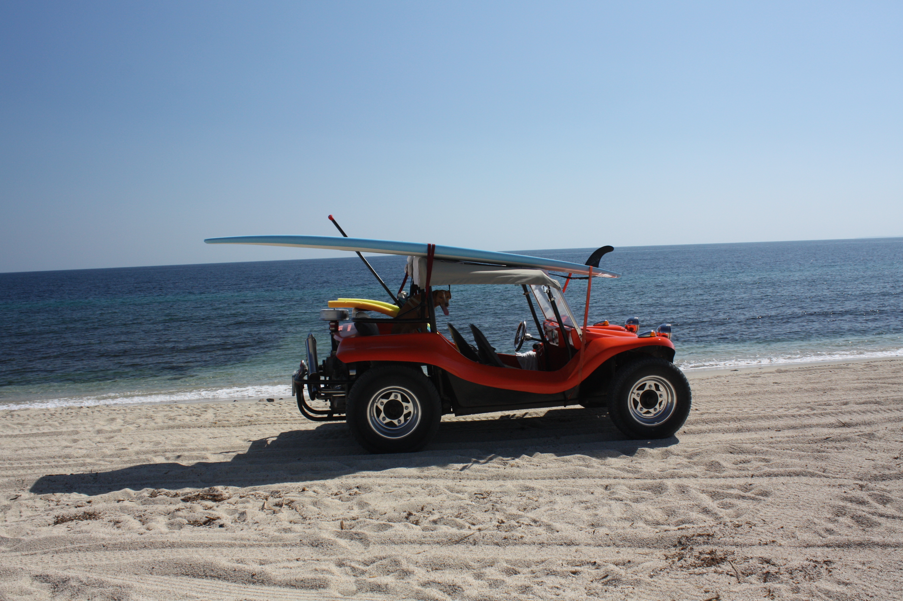


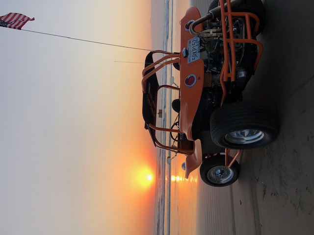


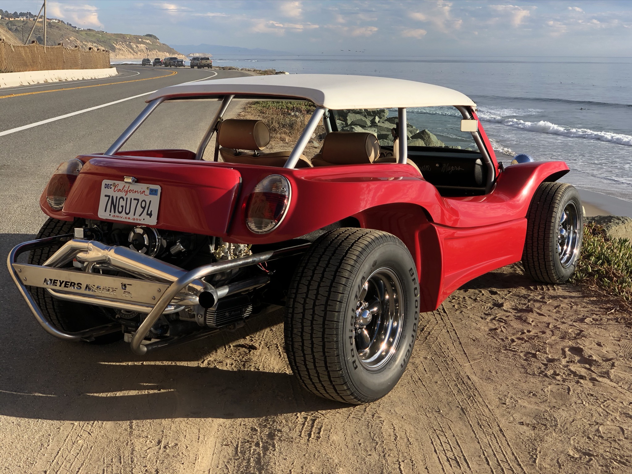


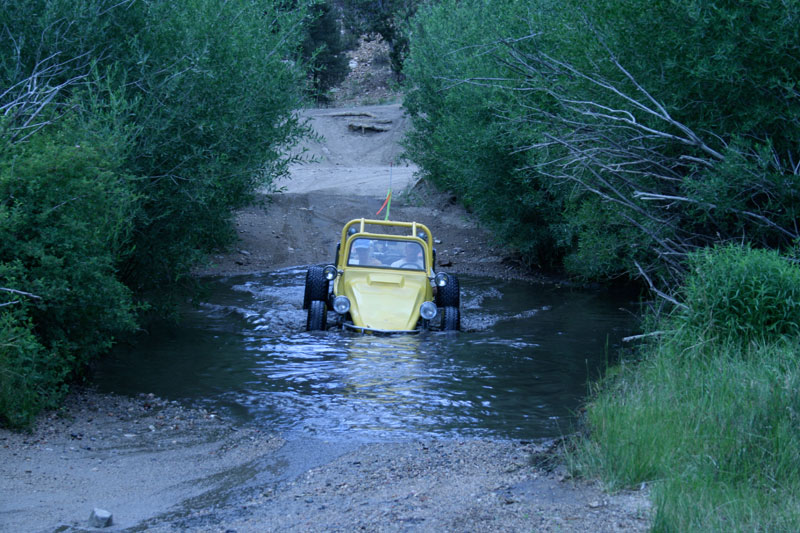


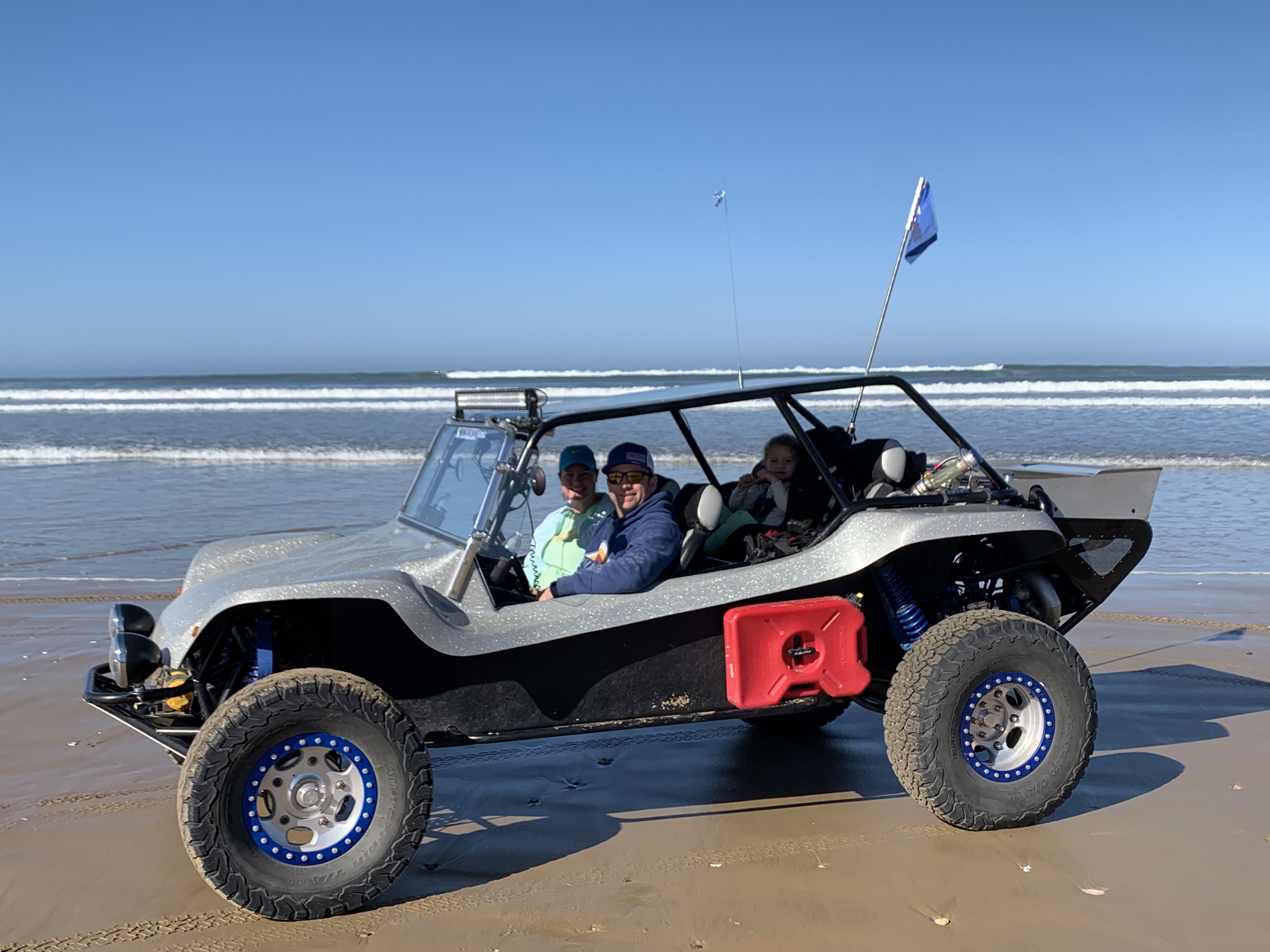

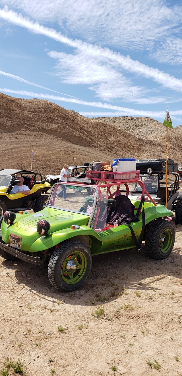


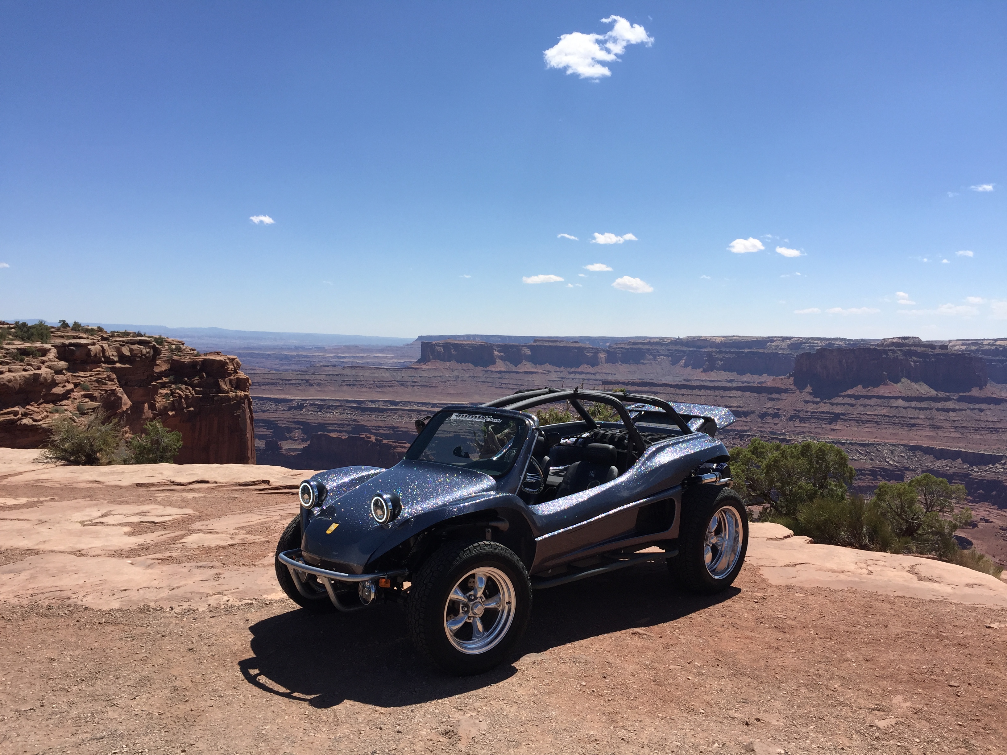


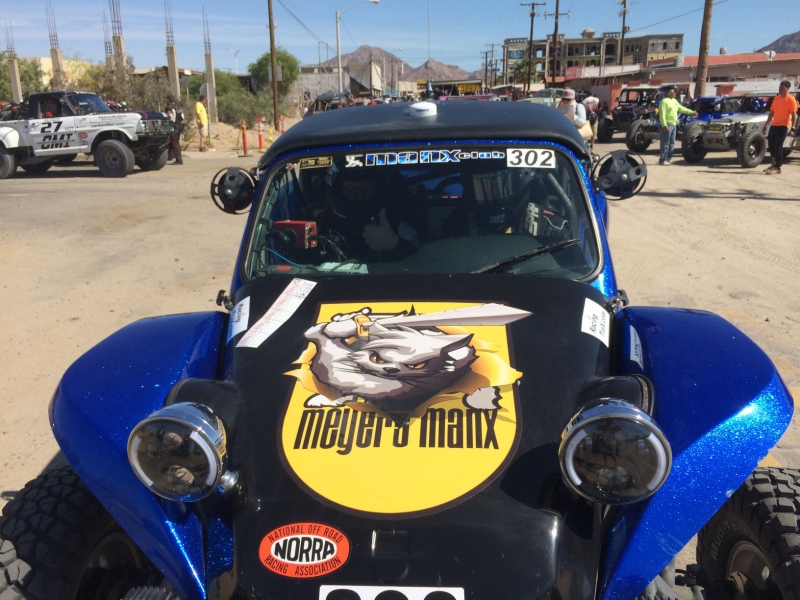


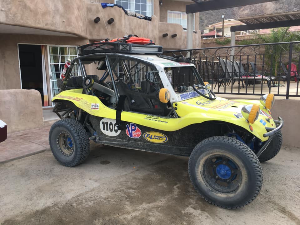


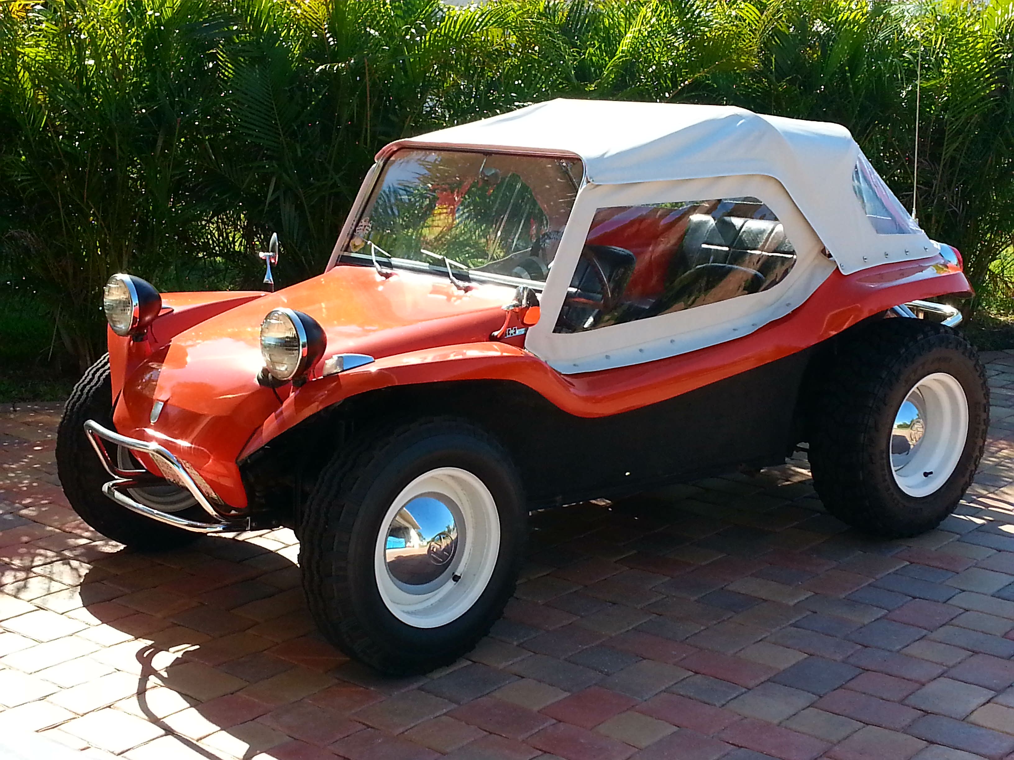
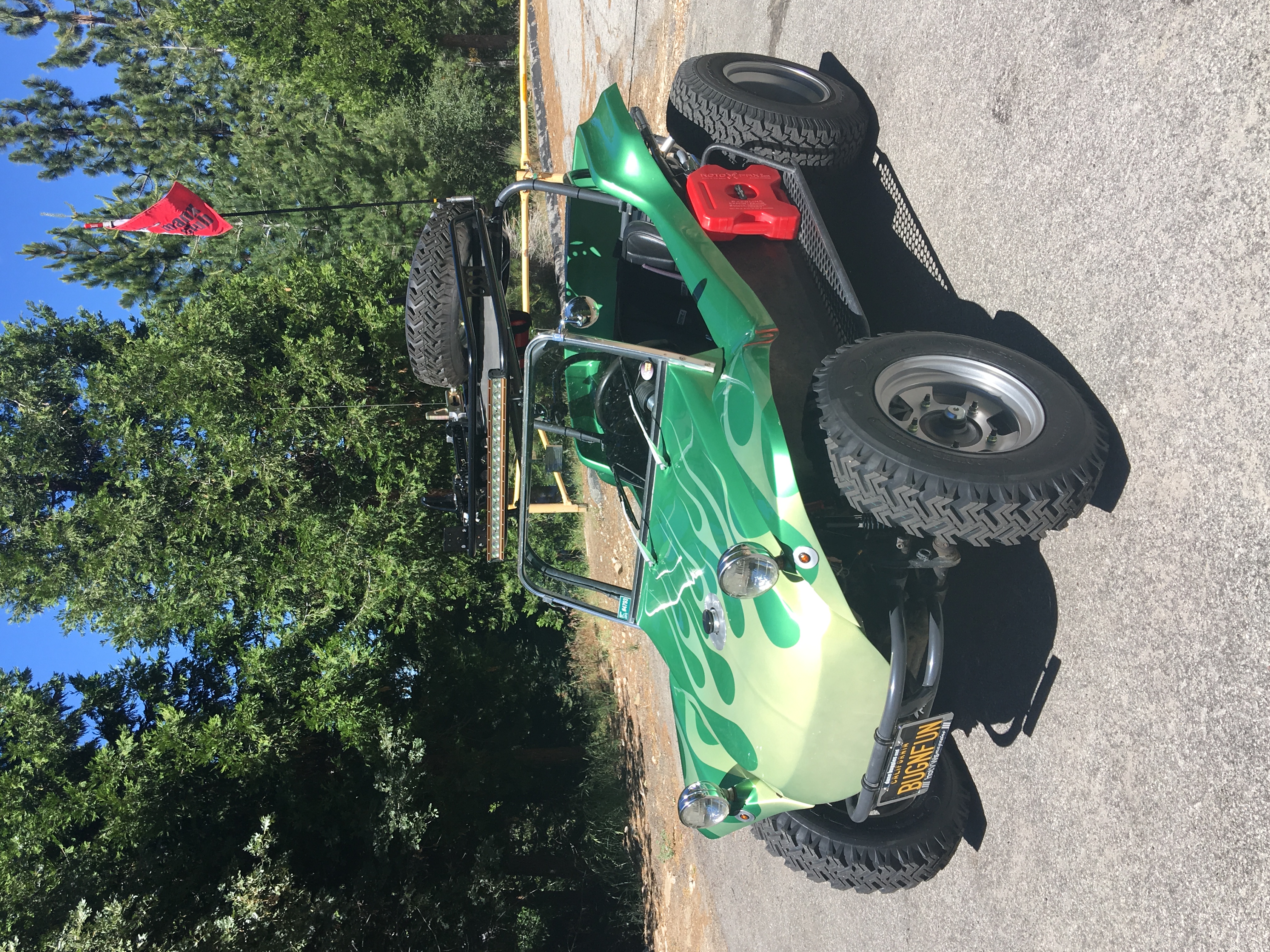


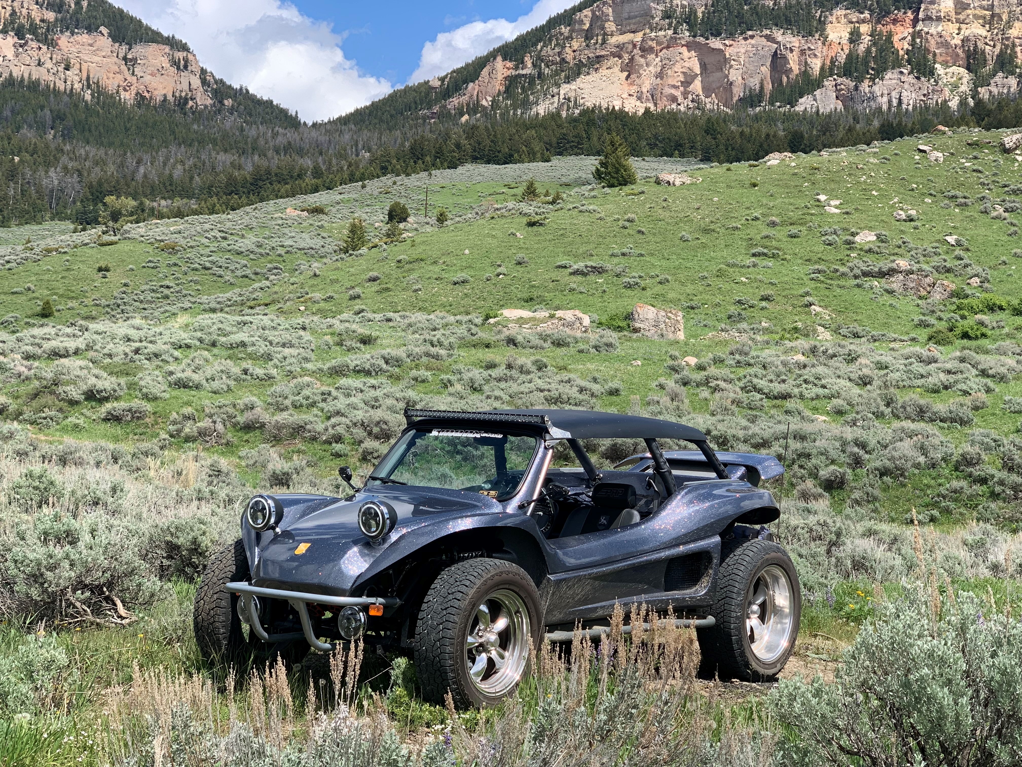

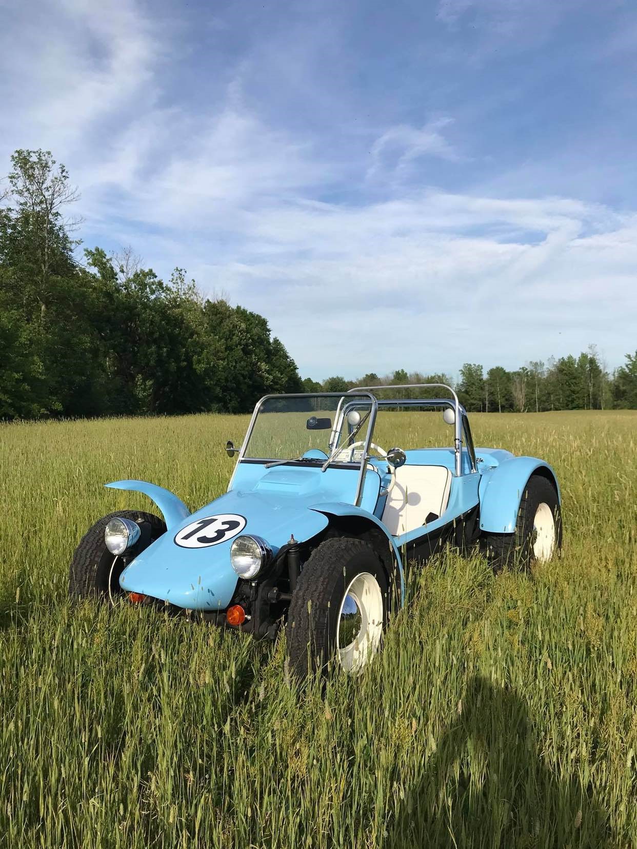

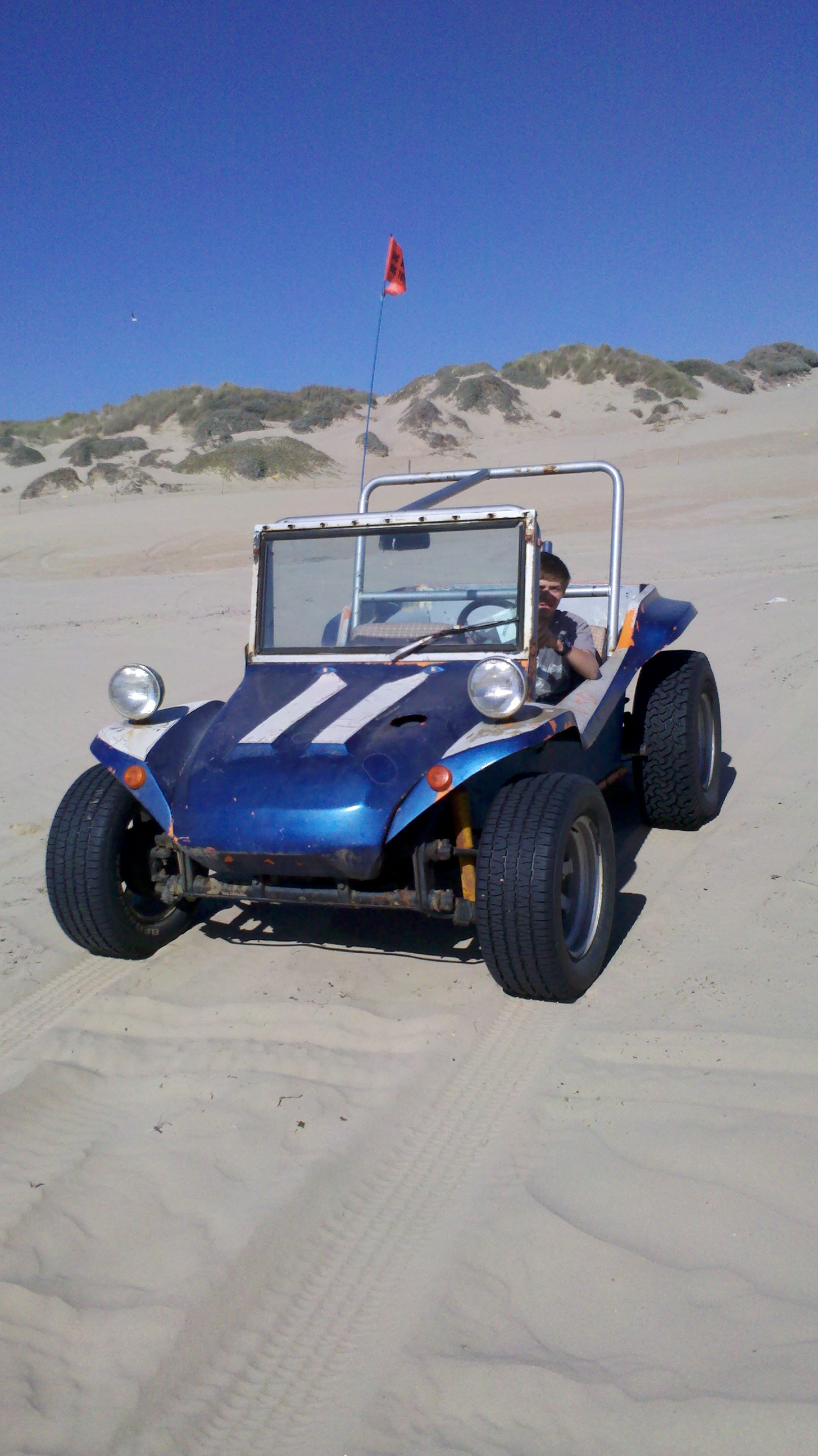


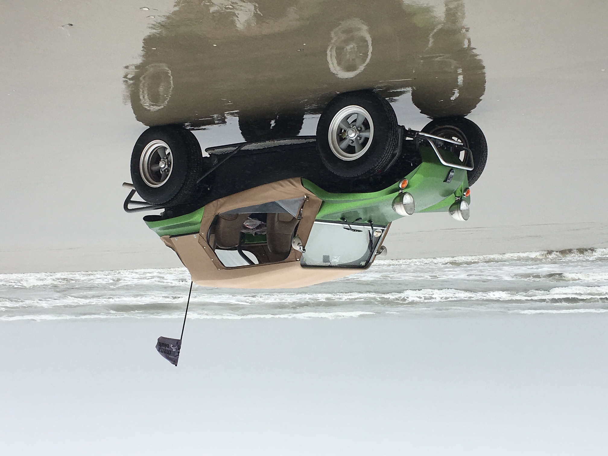
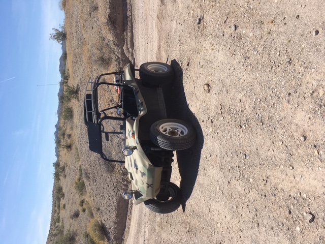


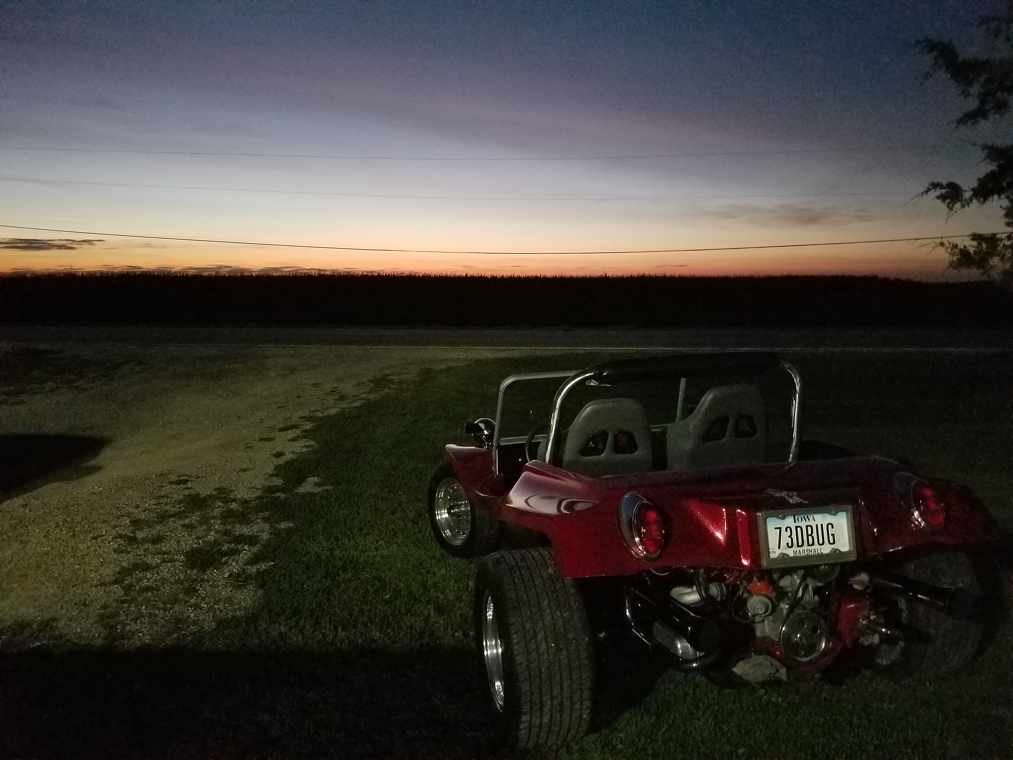
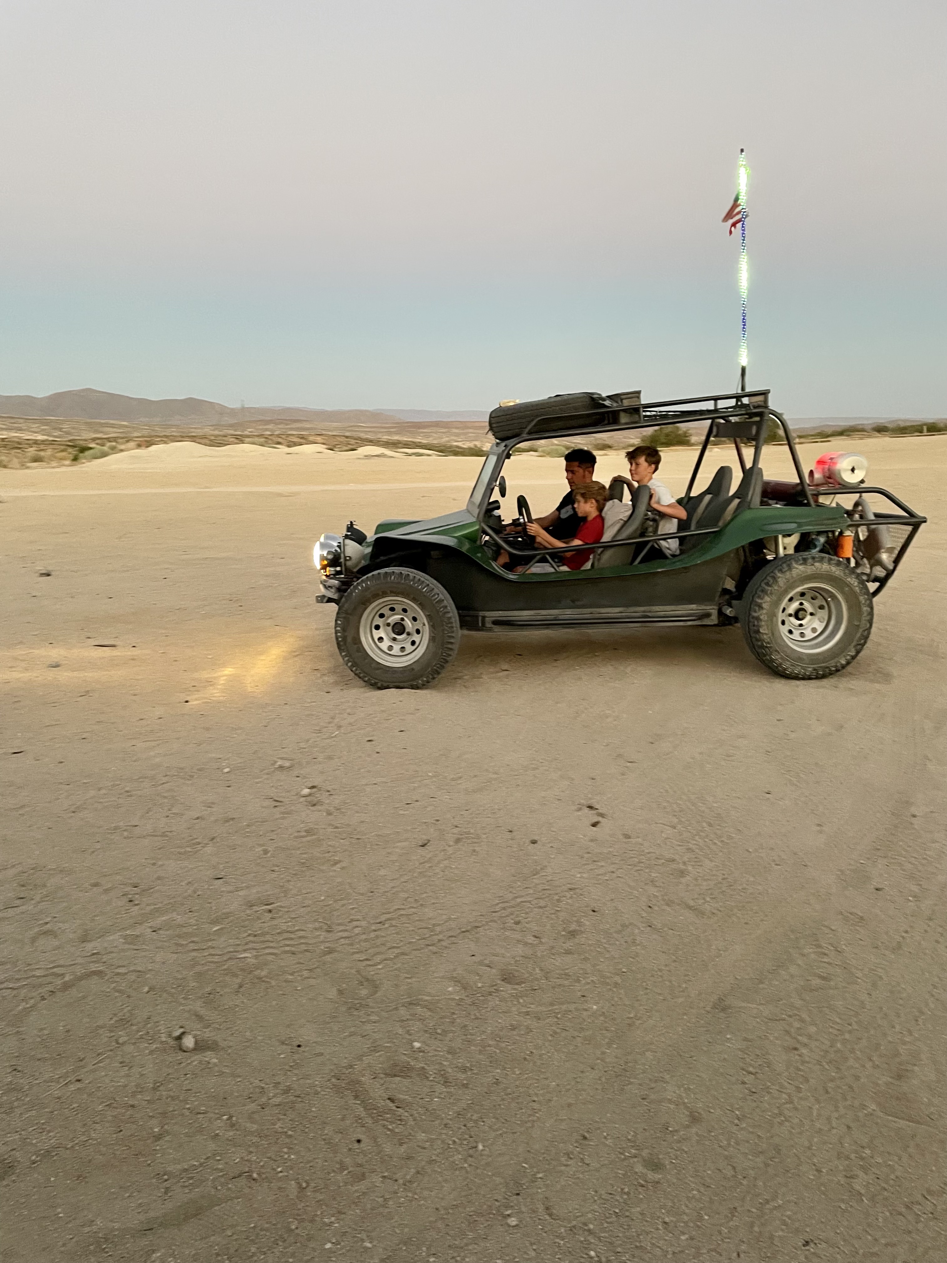


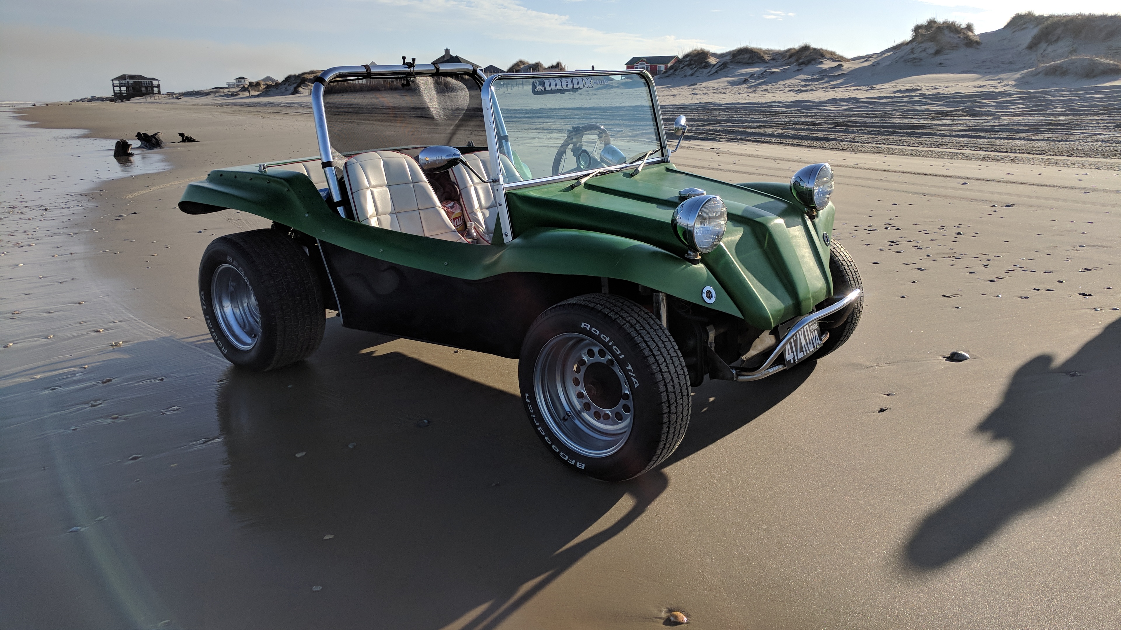


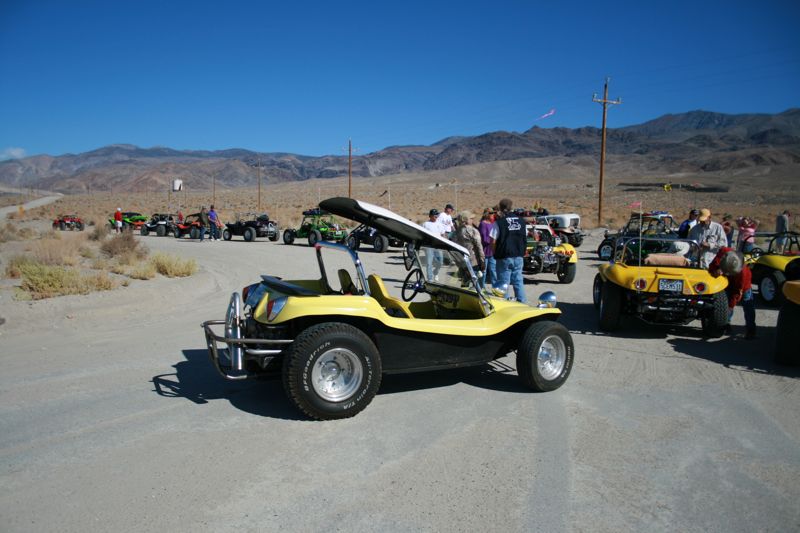


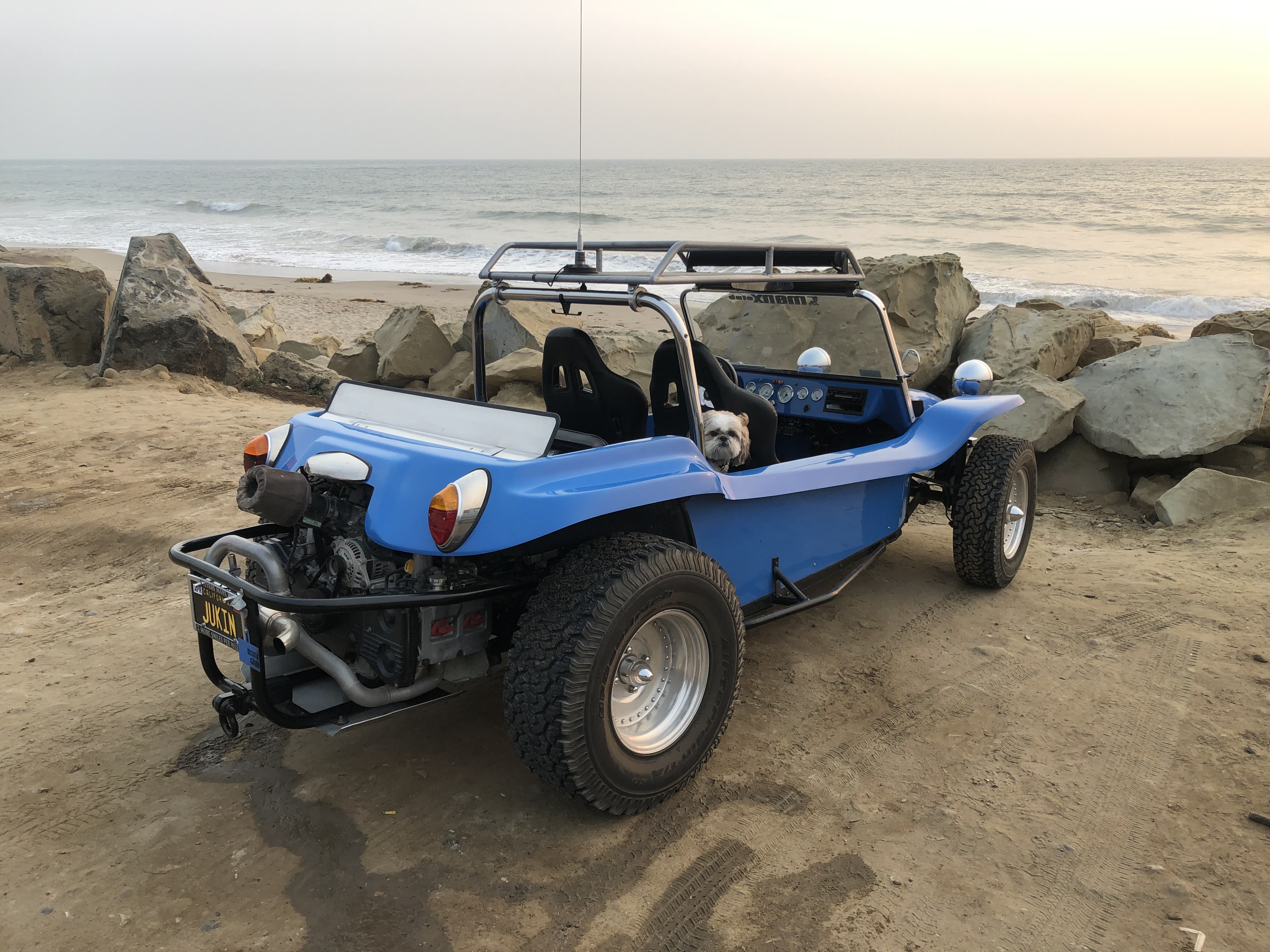
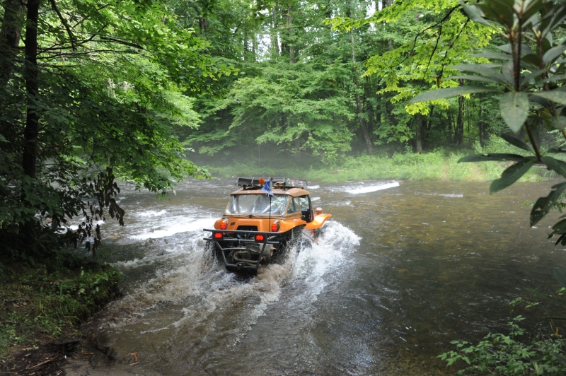
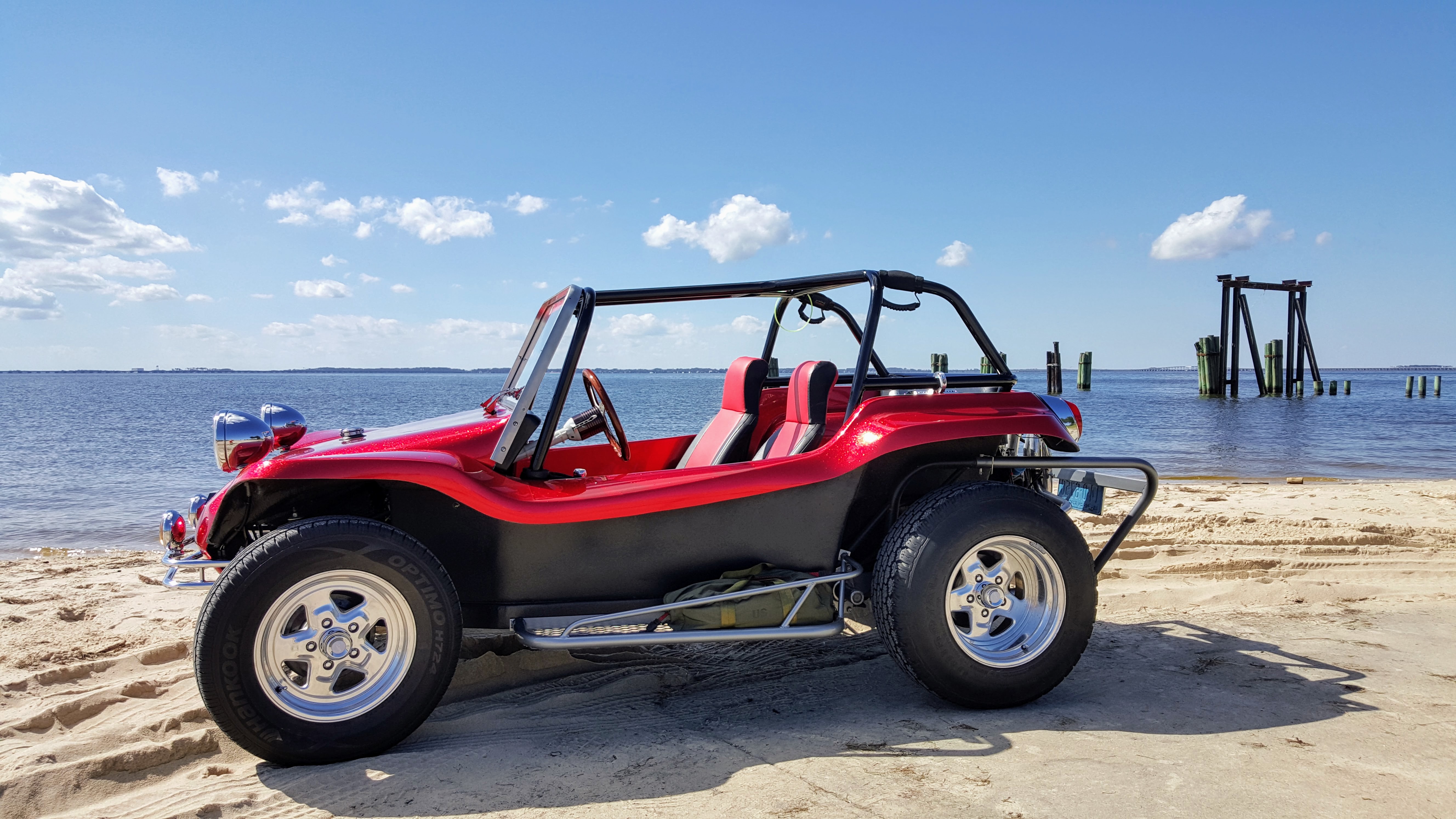

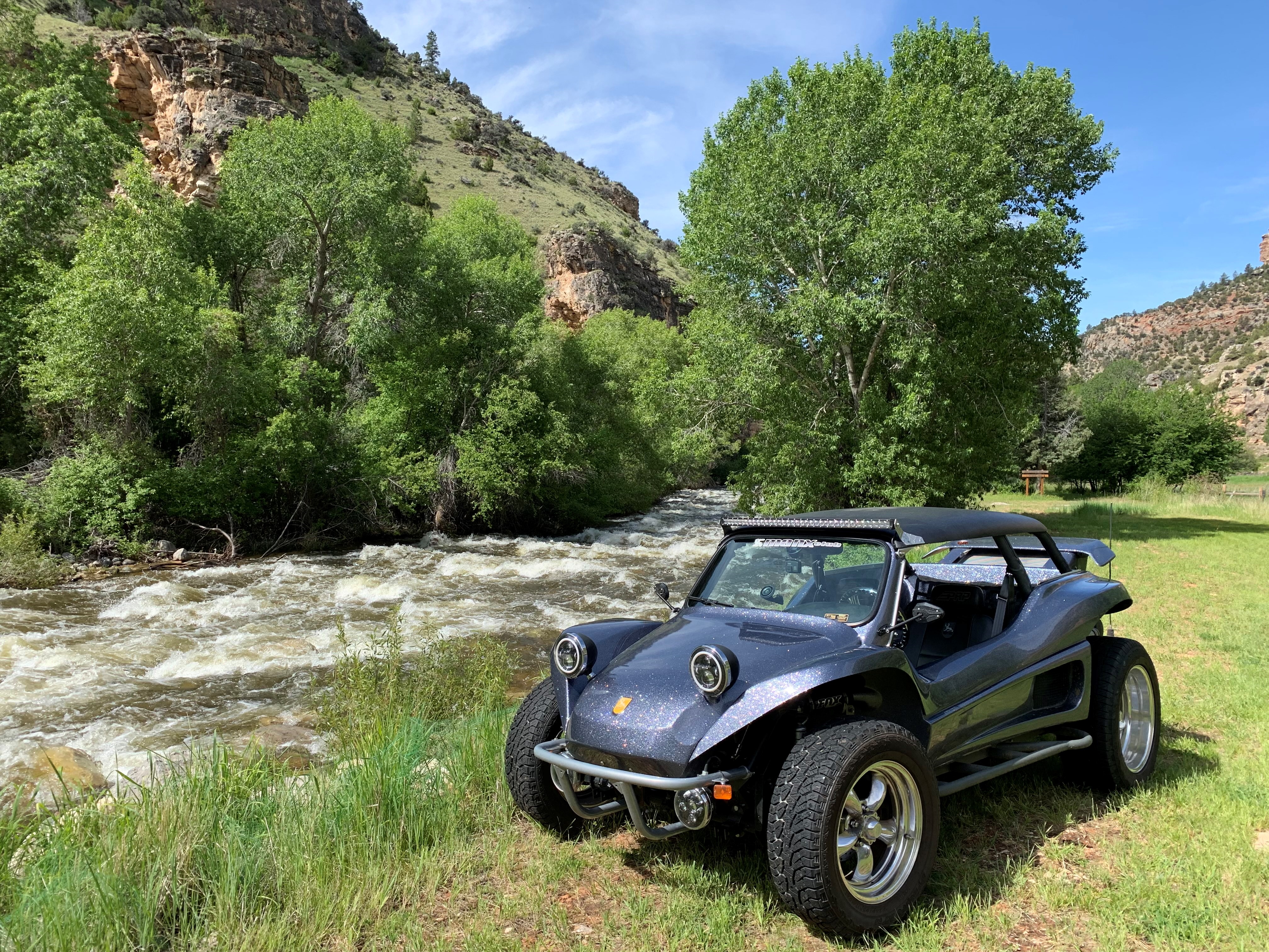

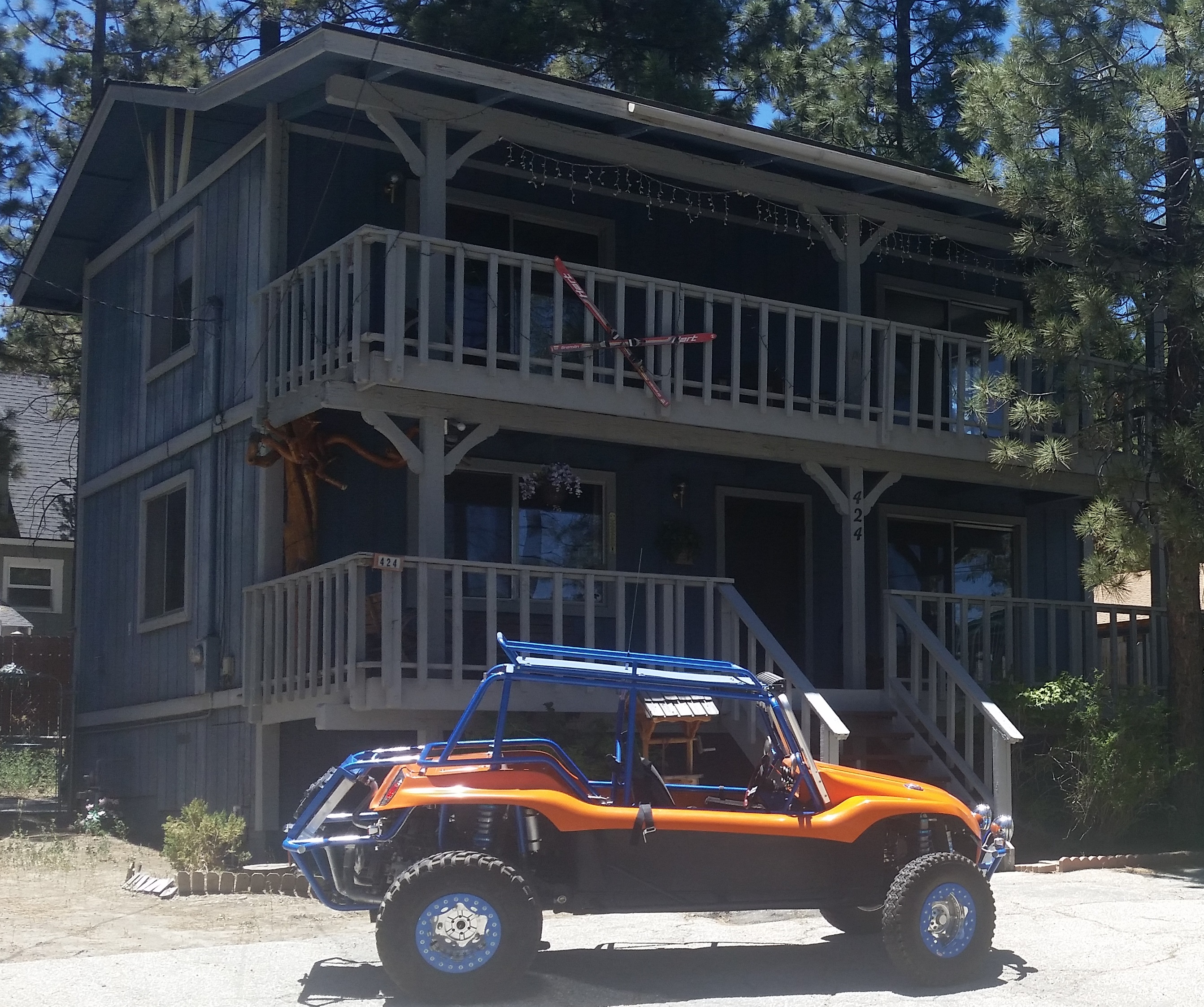
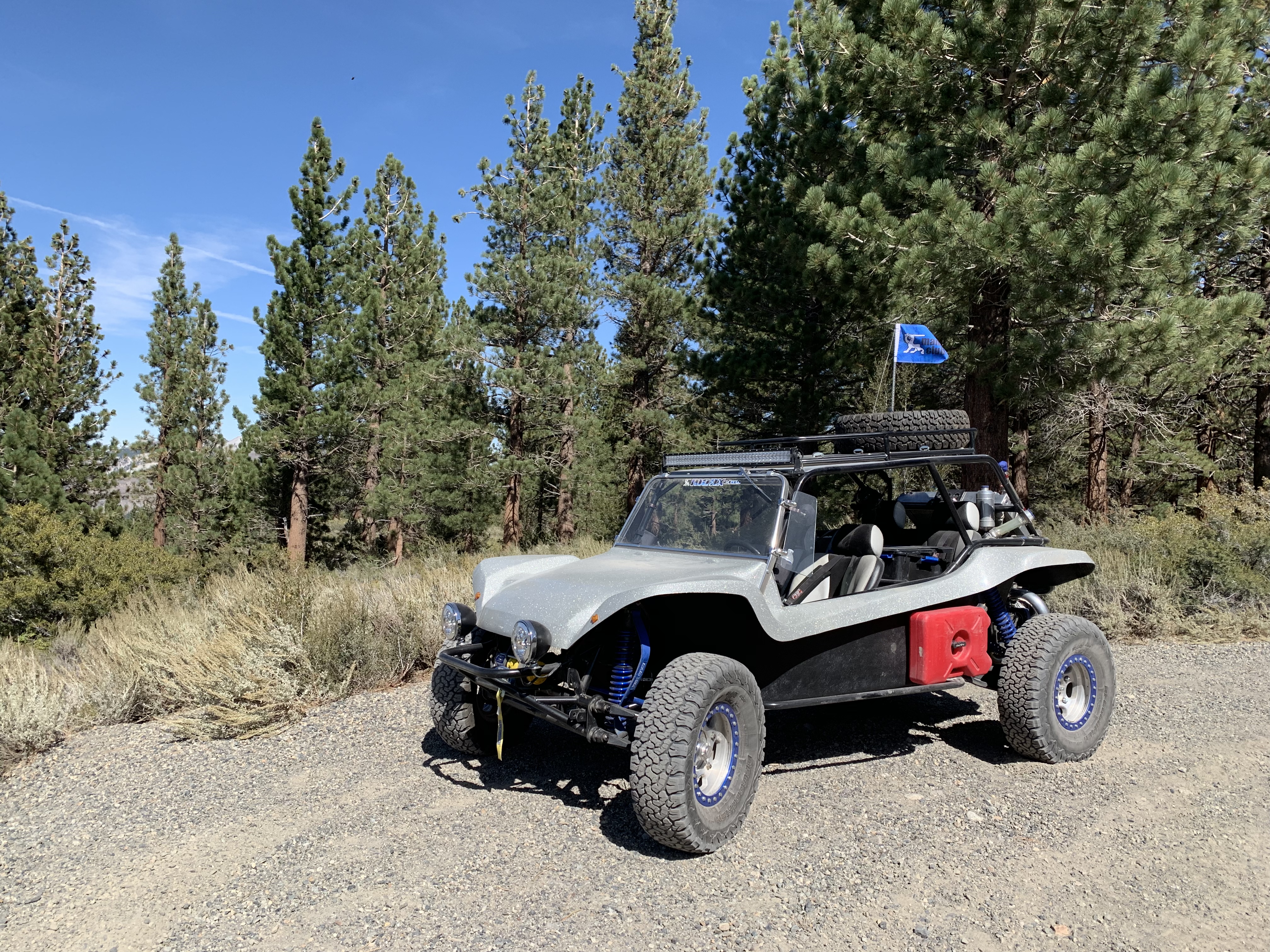
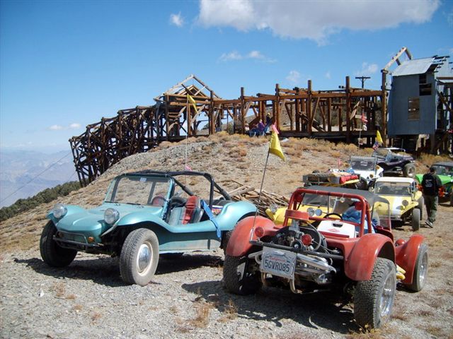


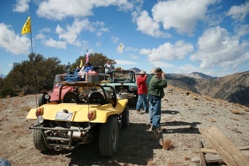
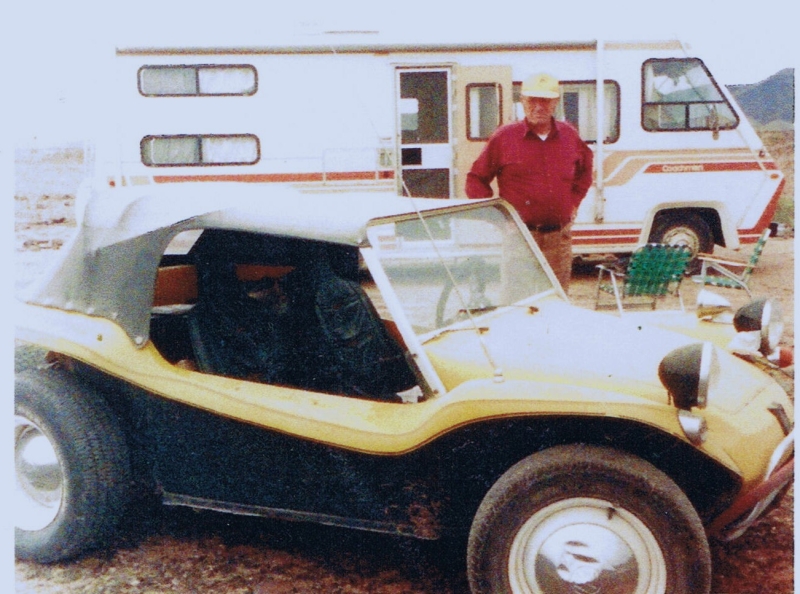


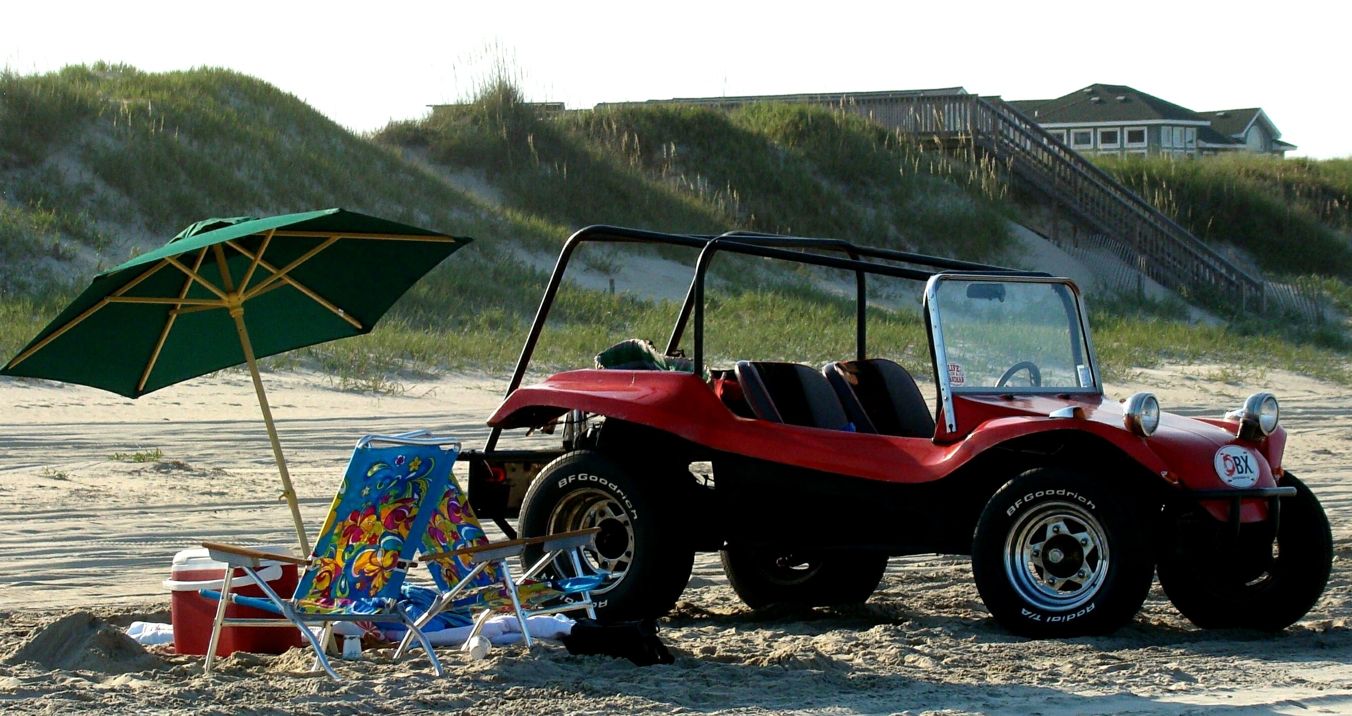

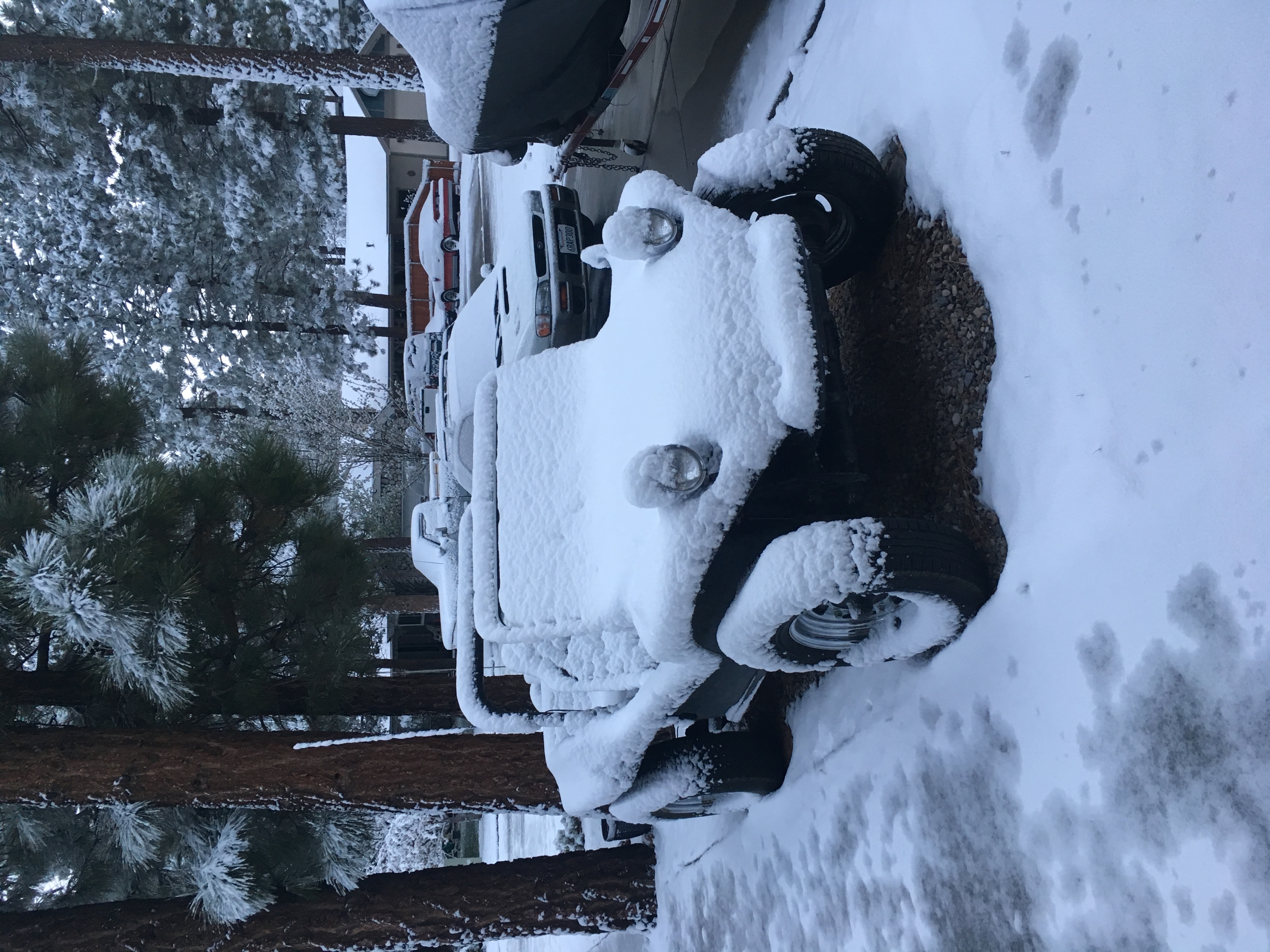


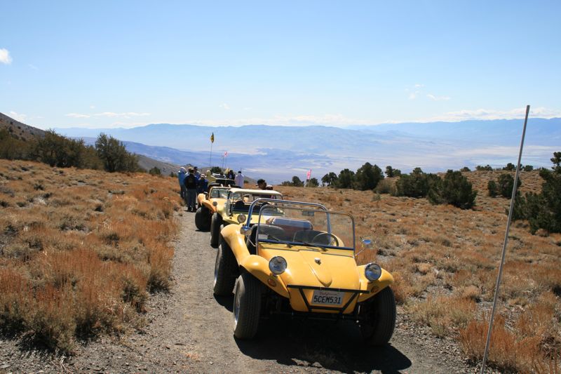

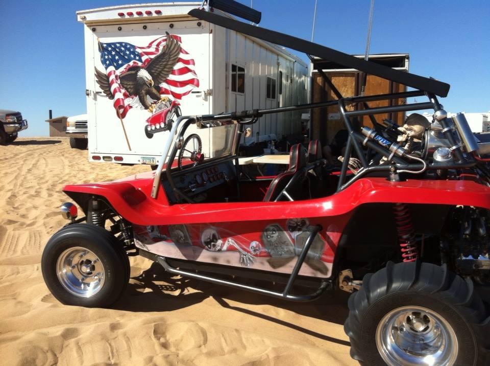


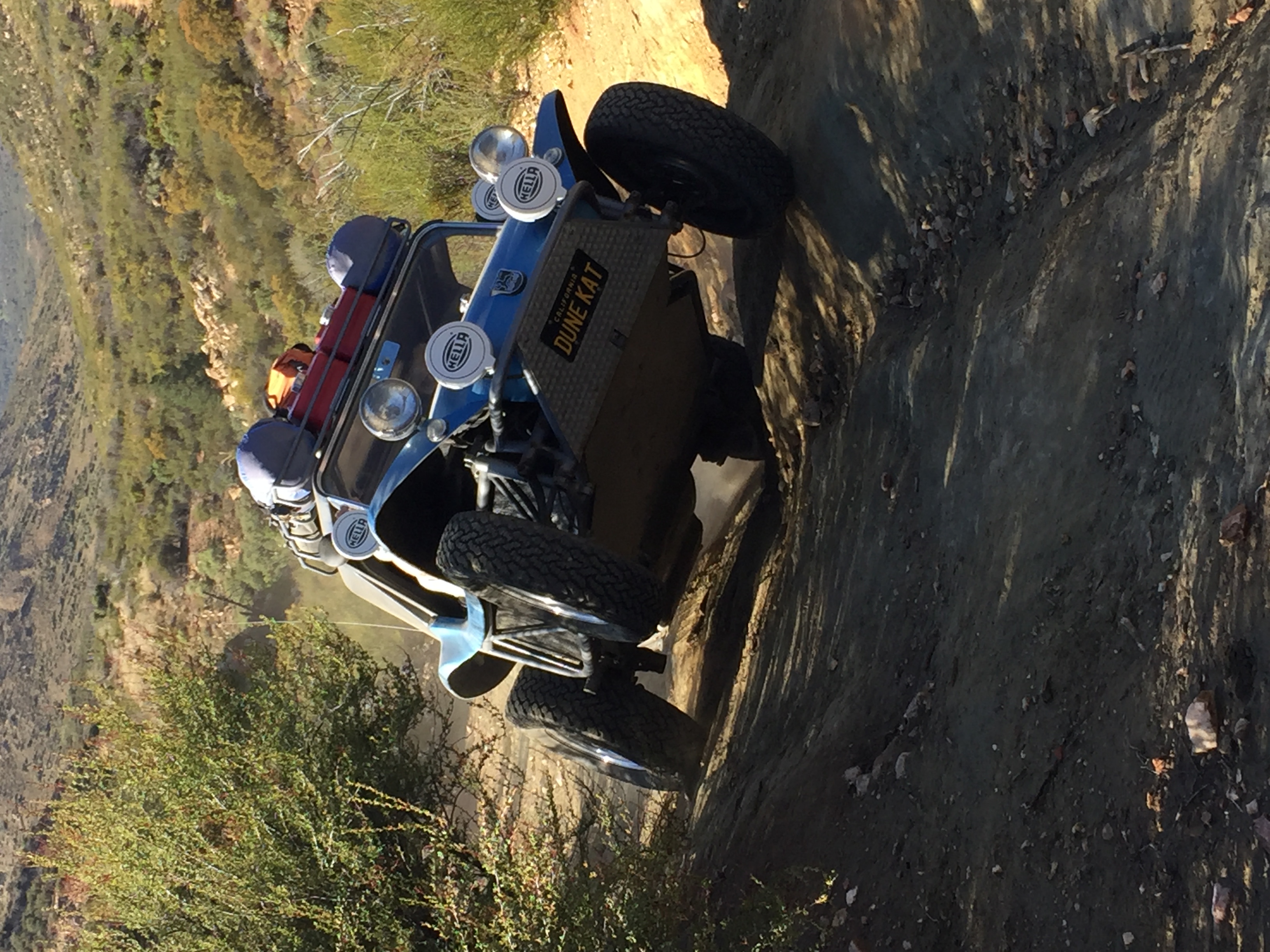

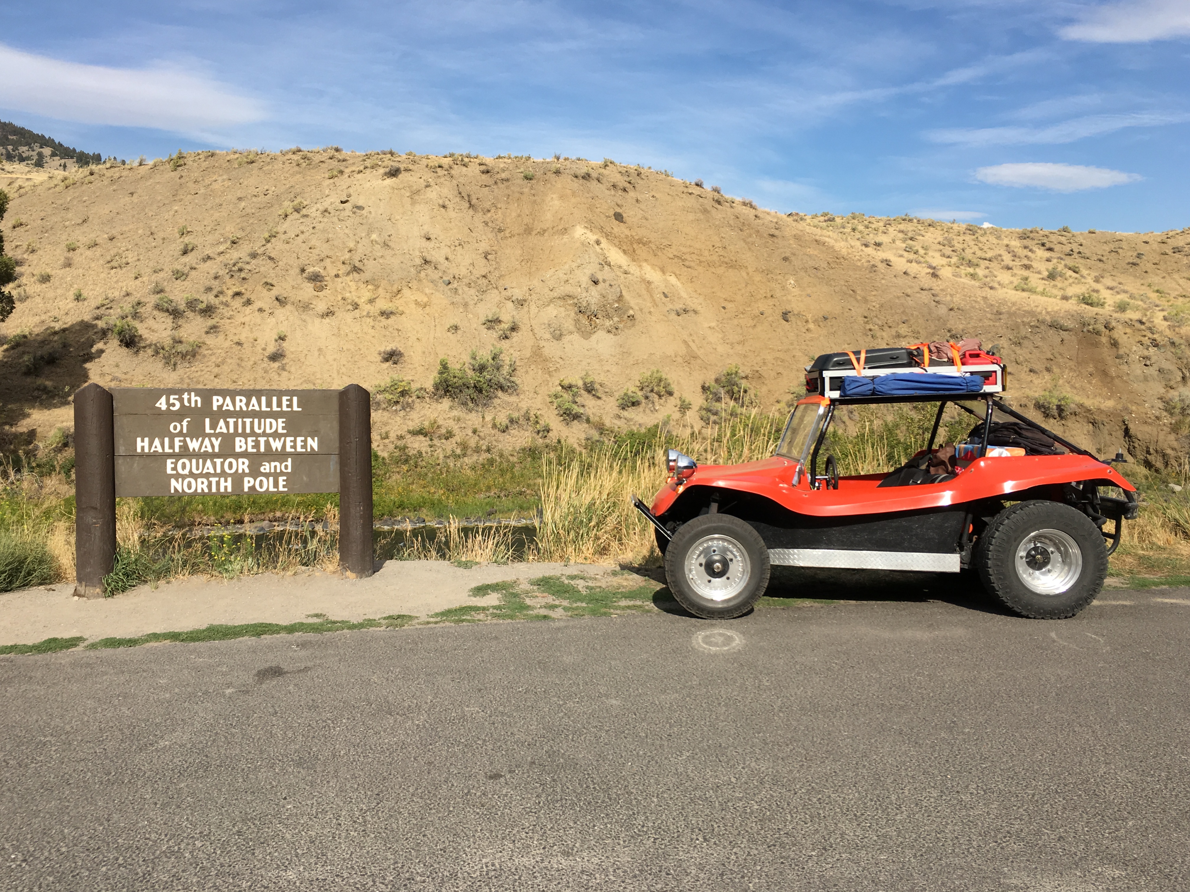


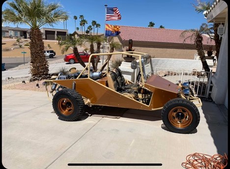

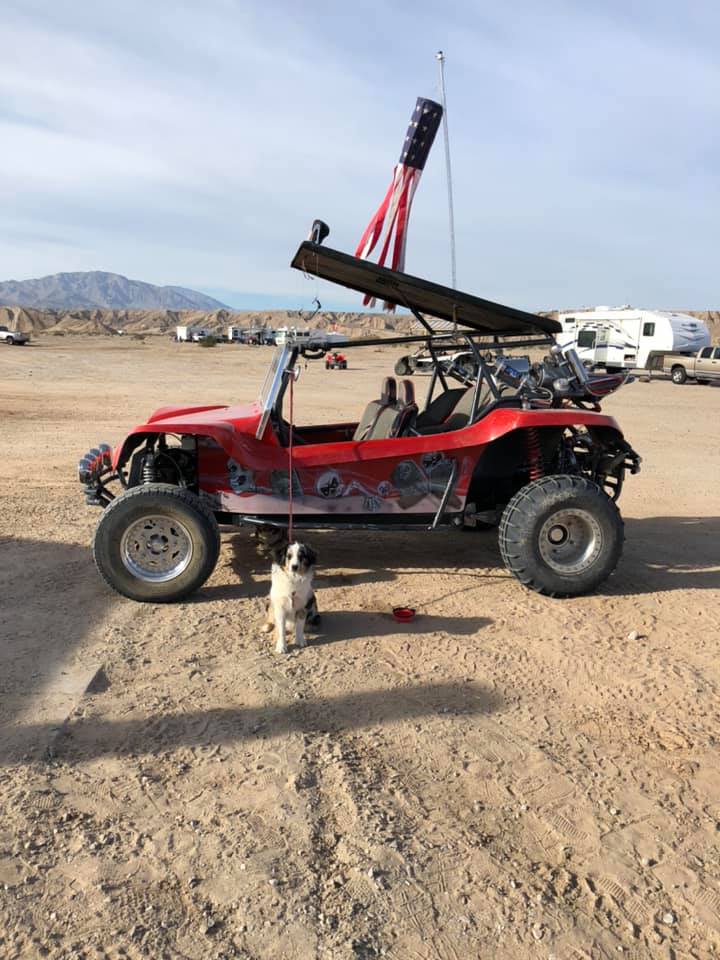


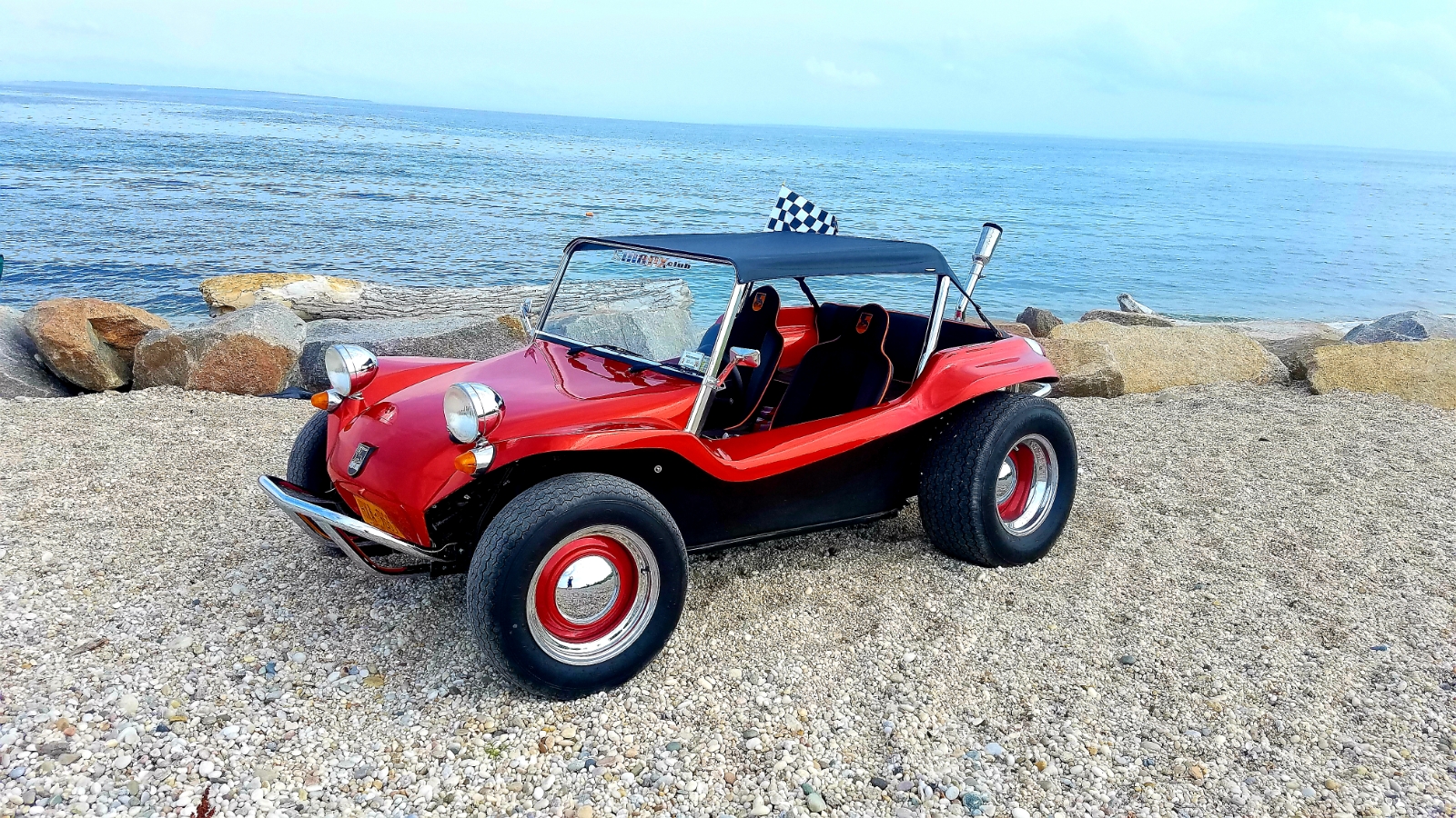
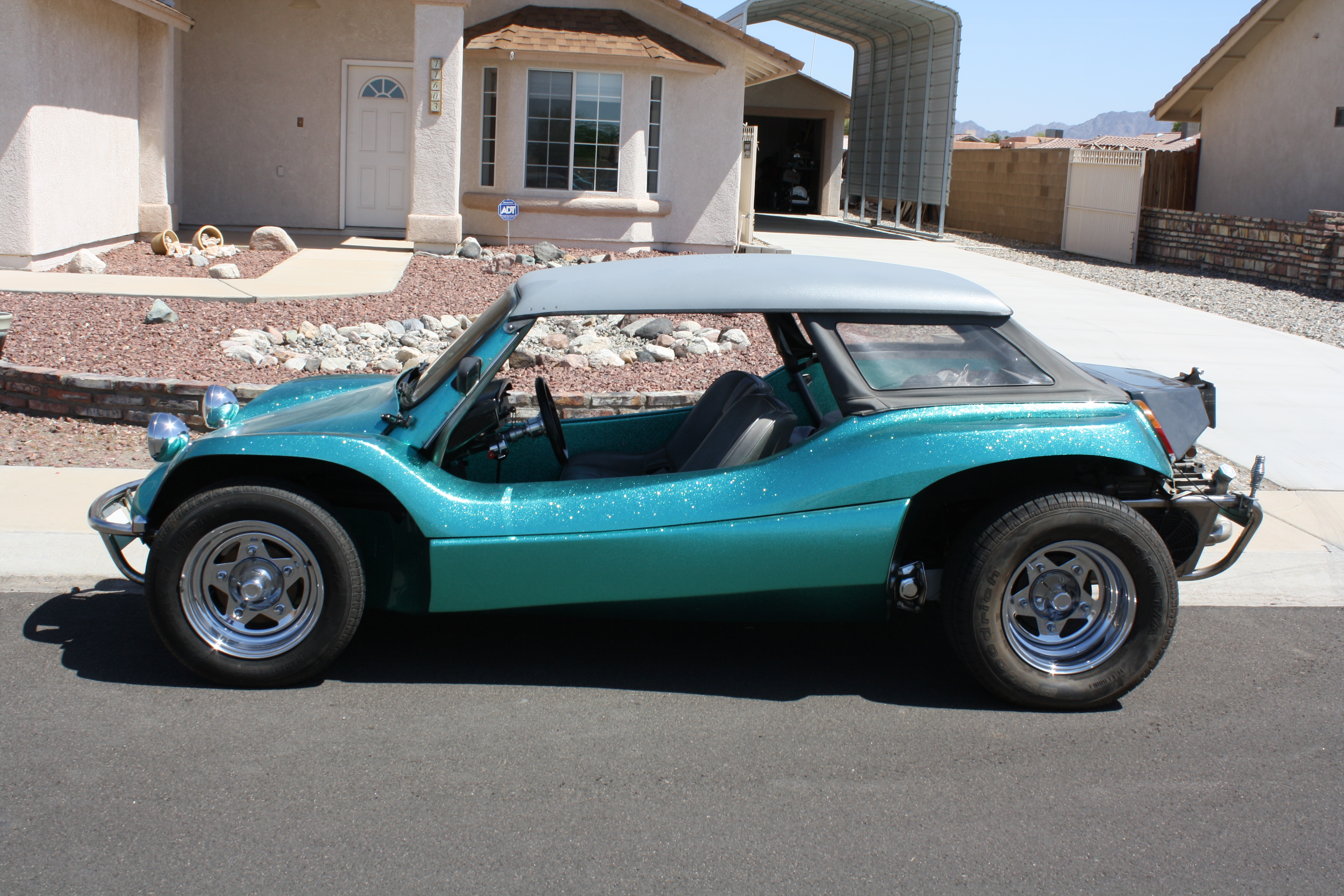


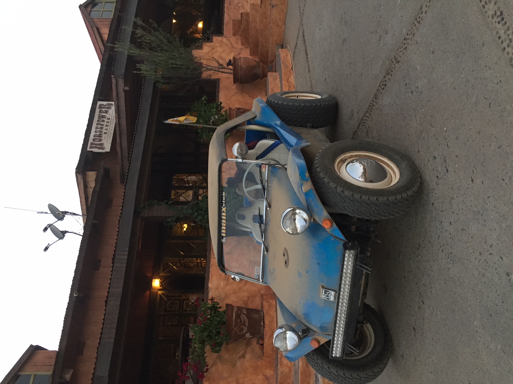


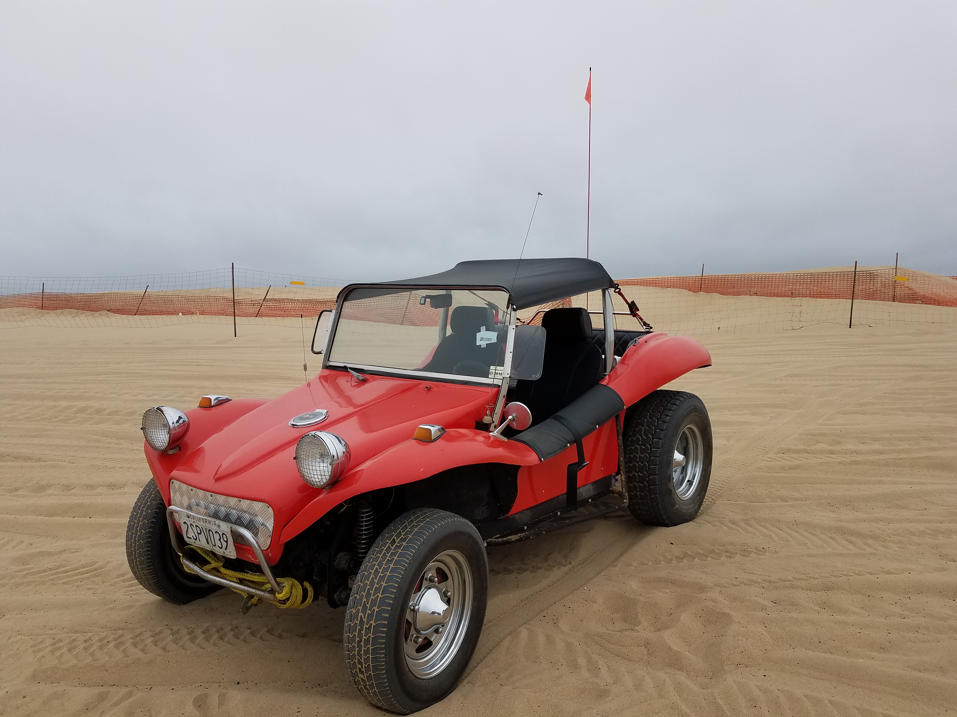


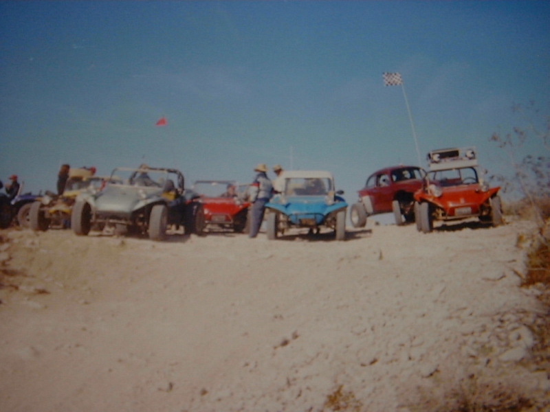

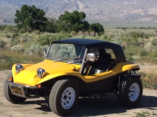


Born on the Beach and in the Desert.
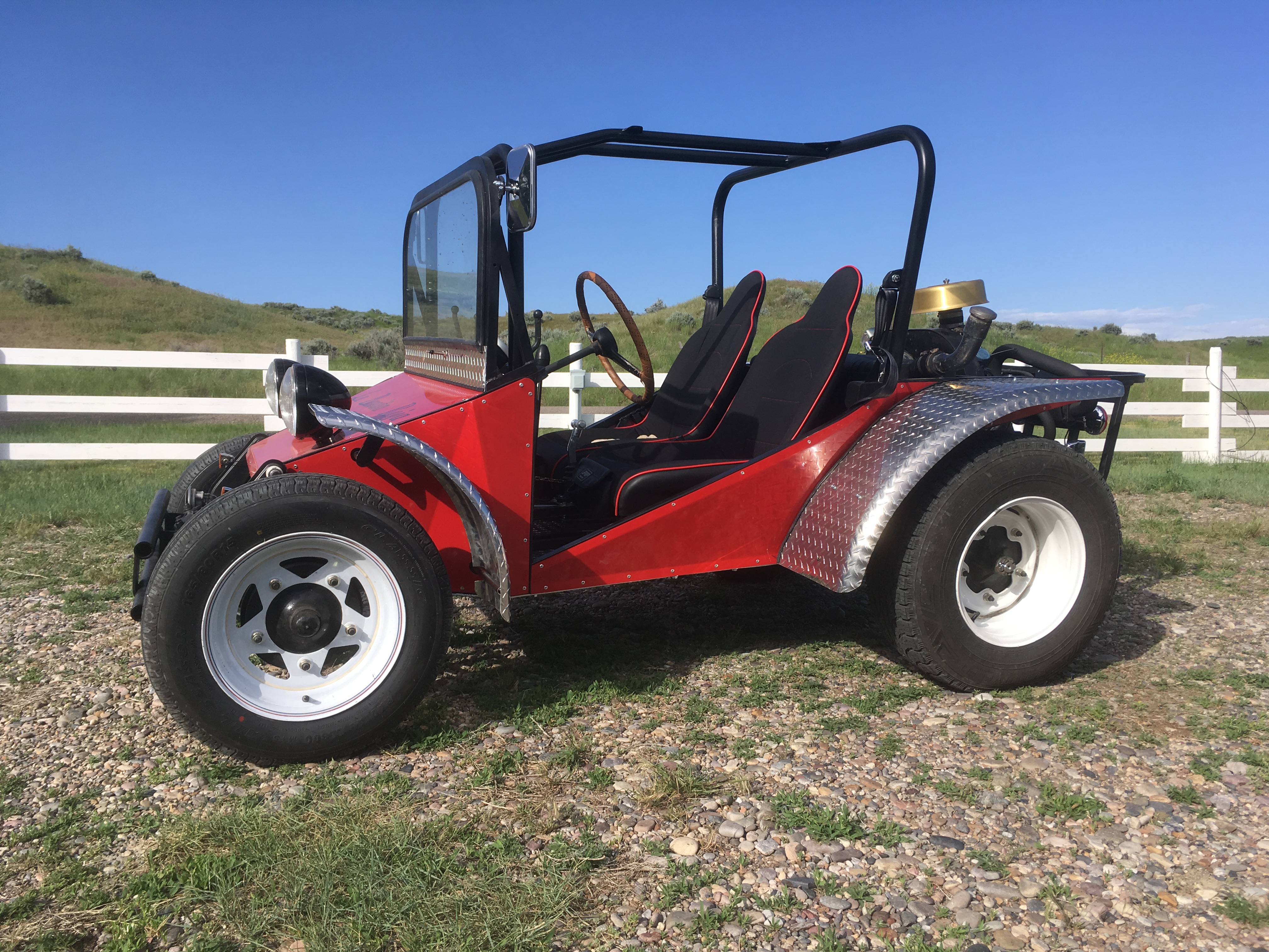
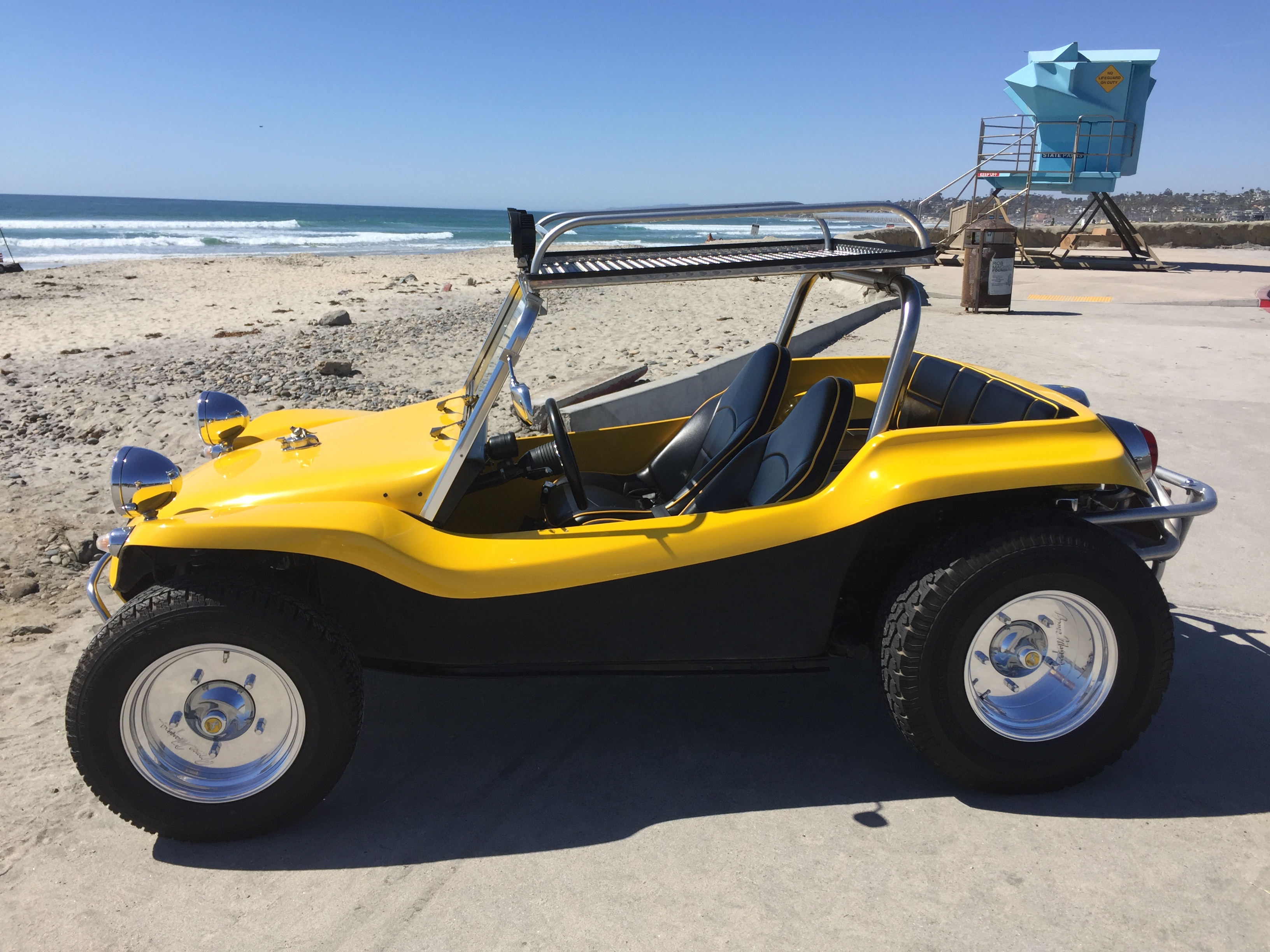
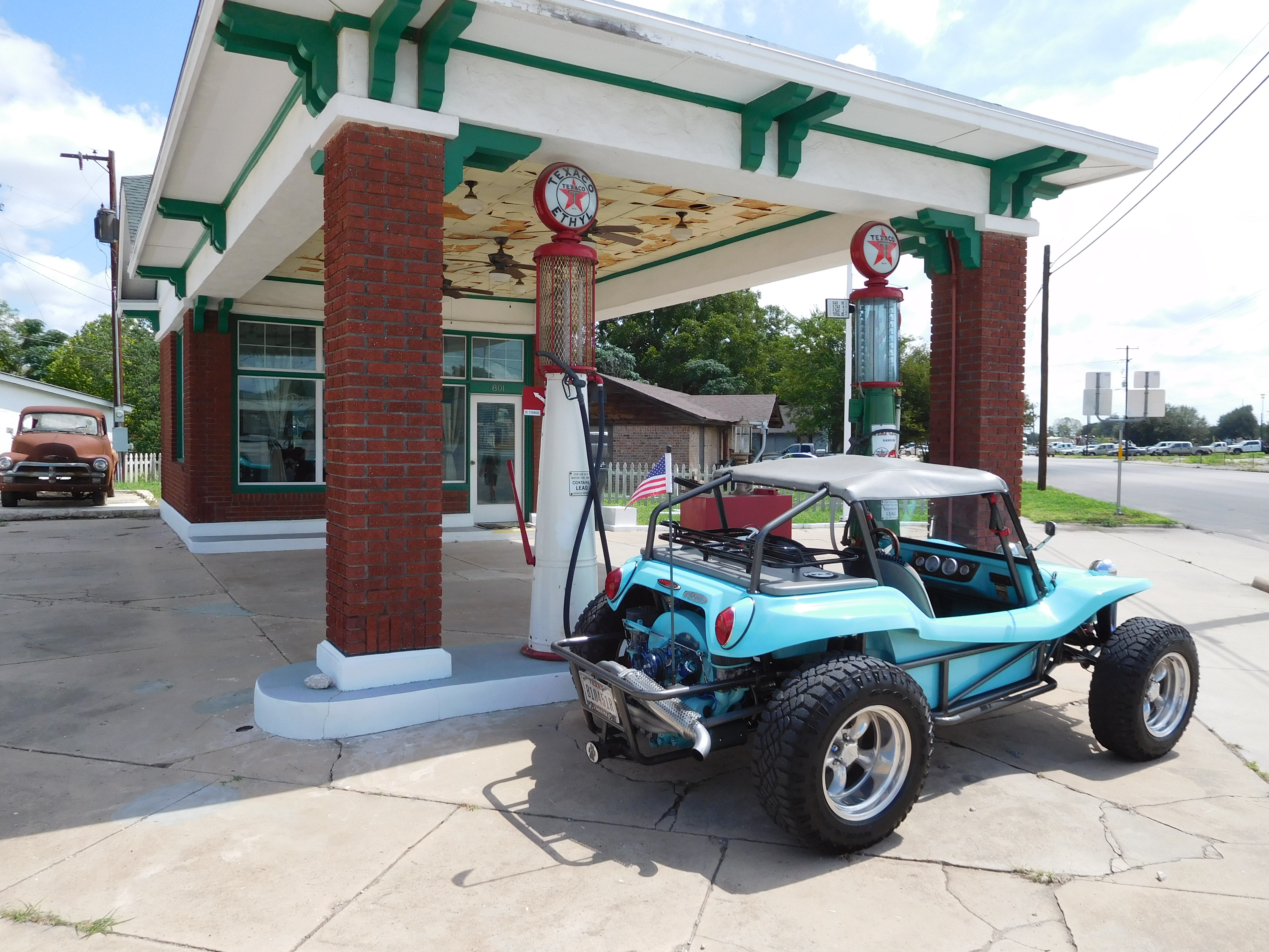
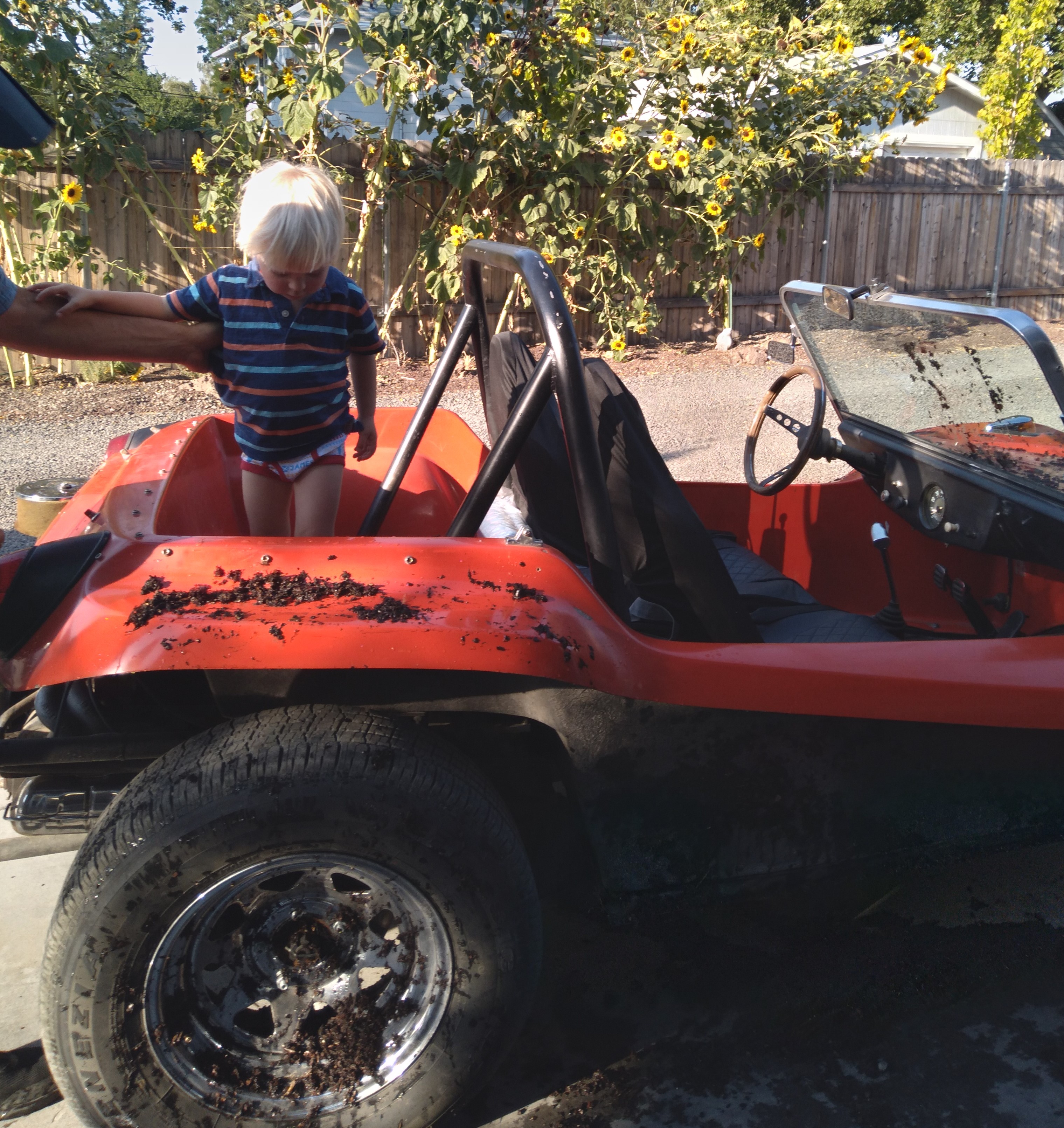
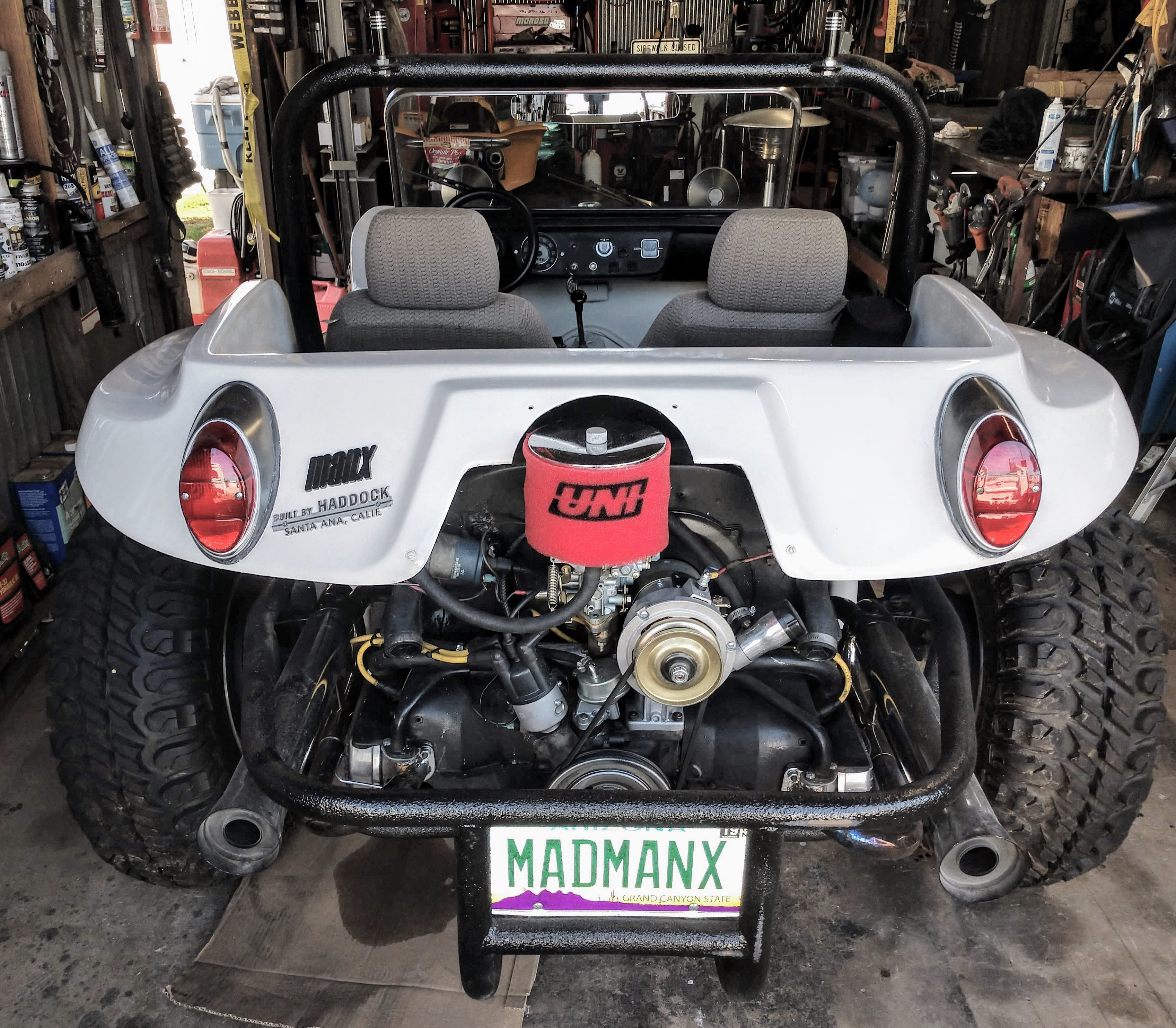
Built to Run Forever.
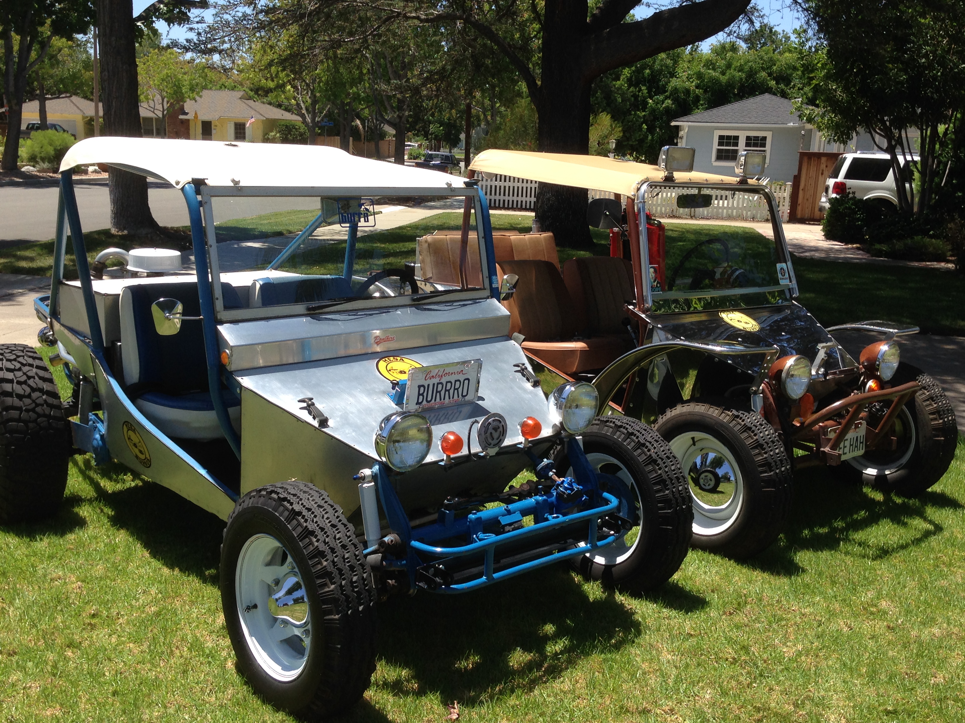
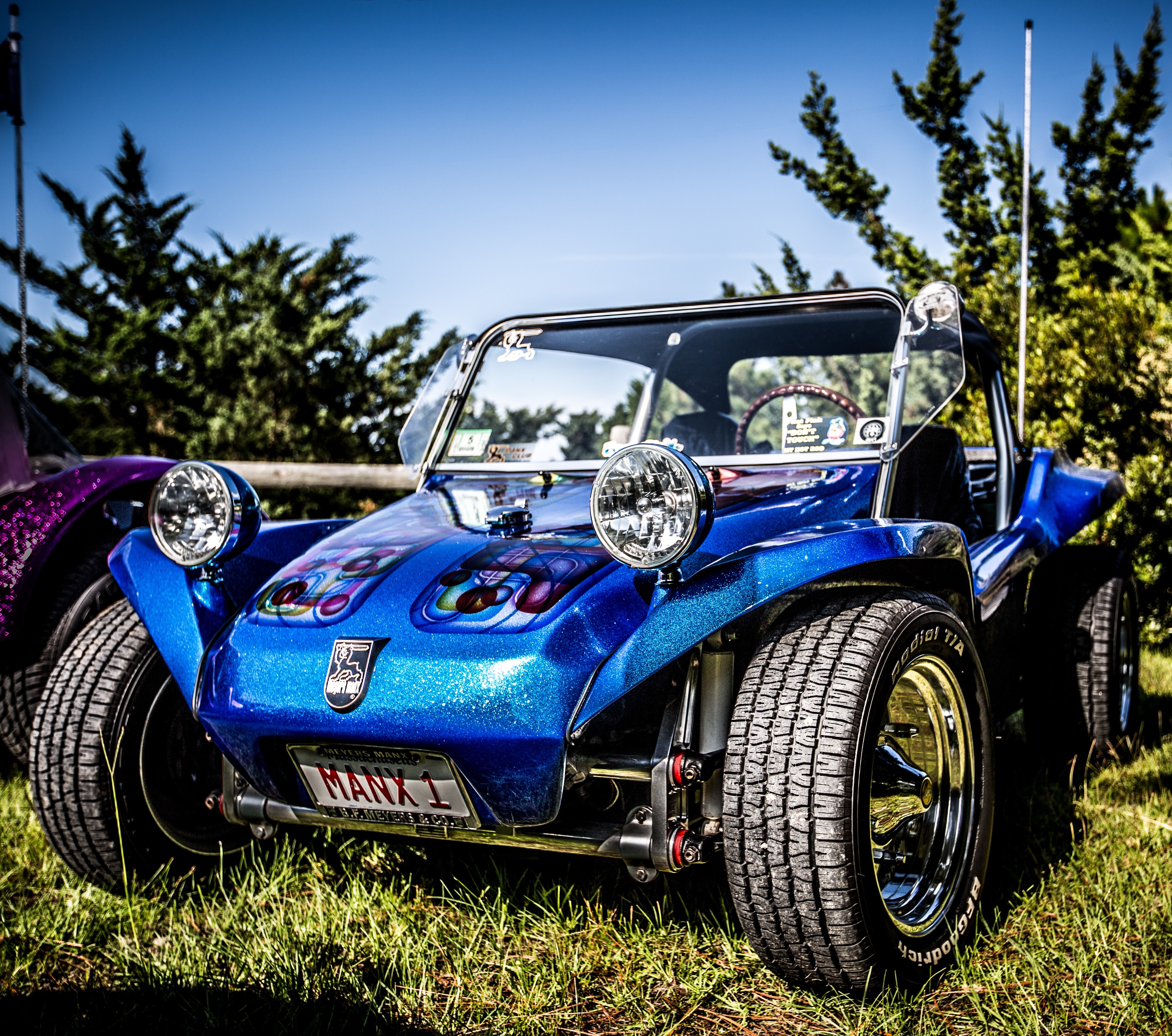
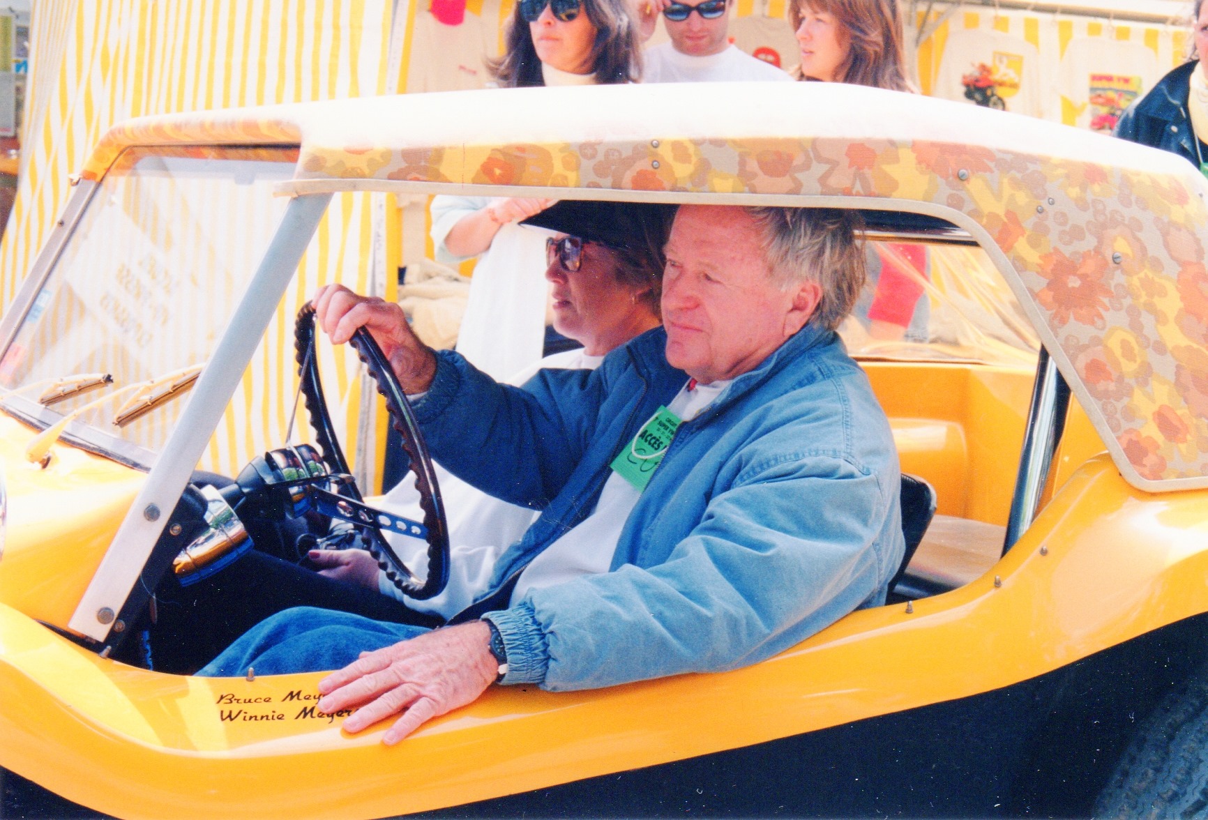
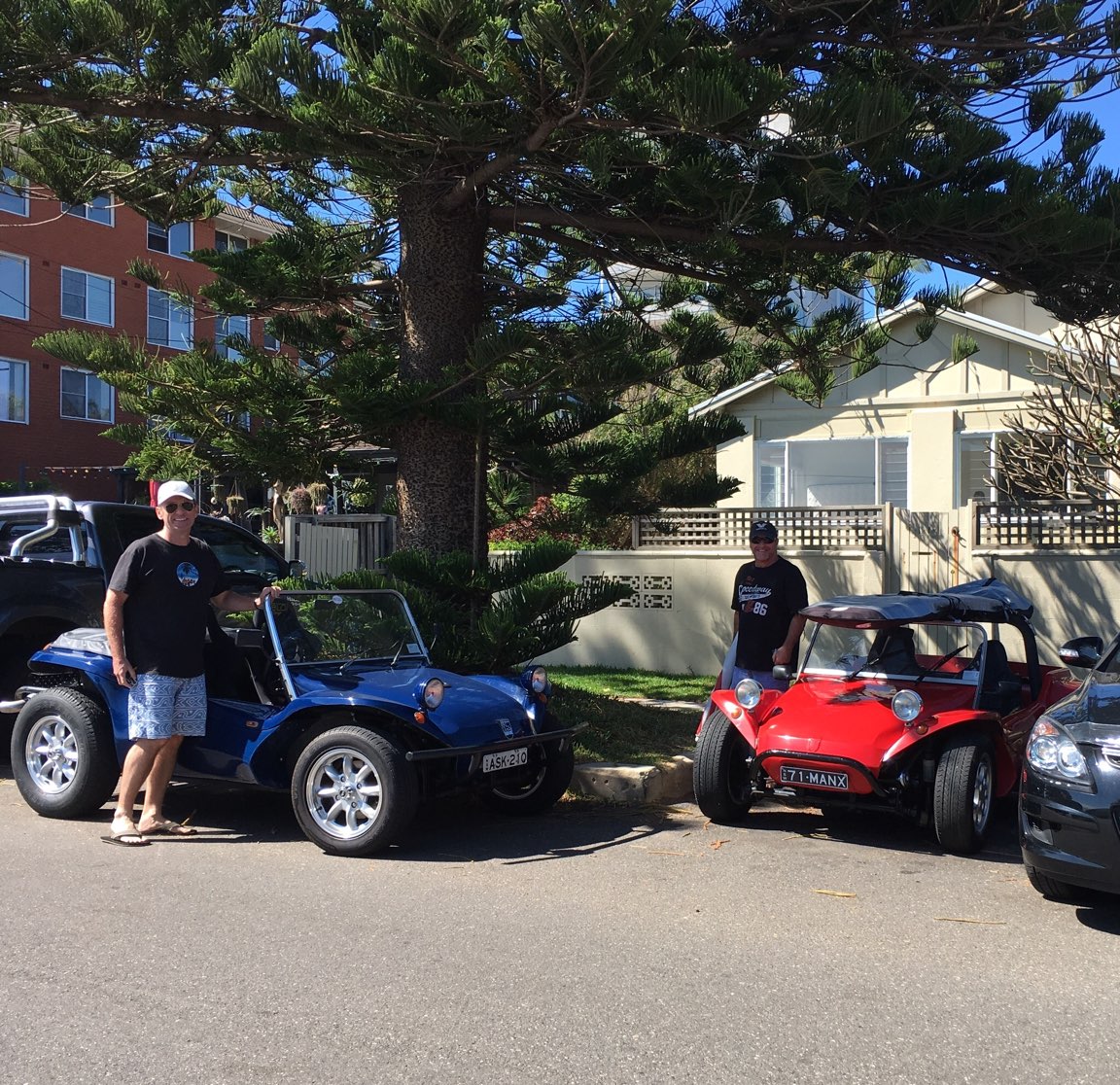
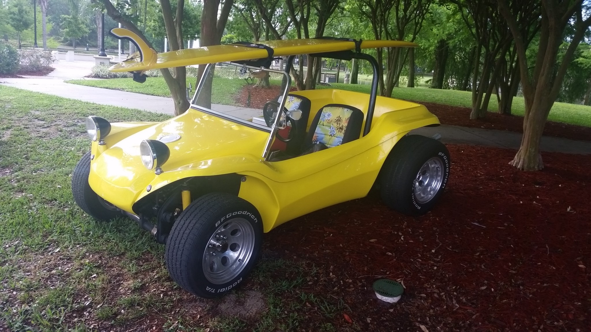
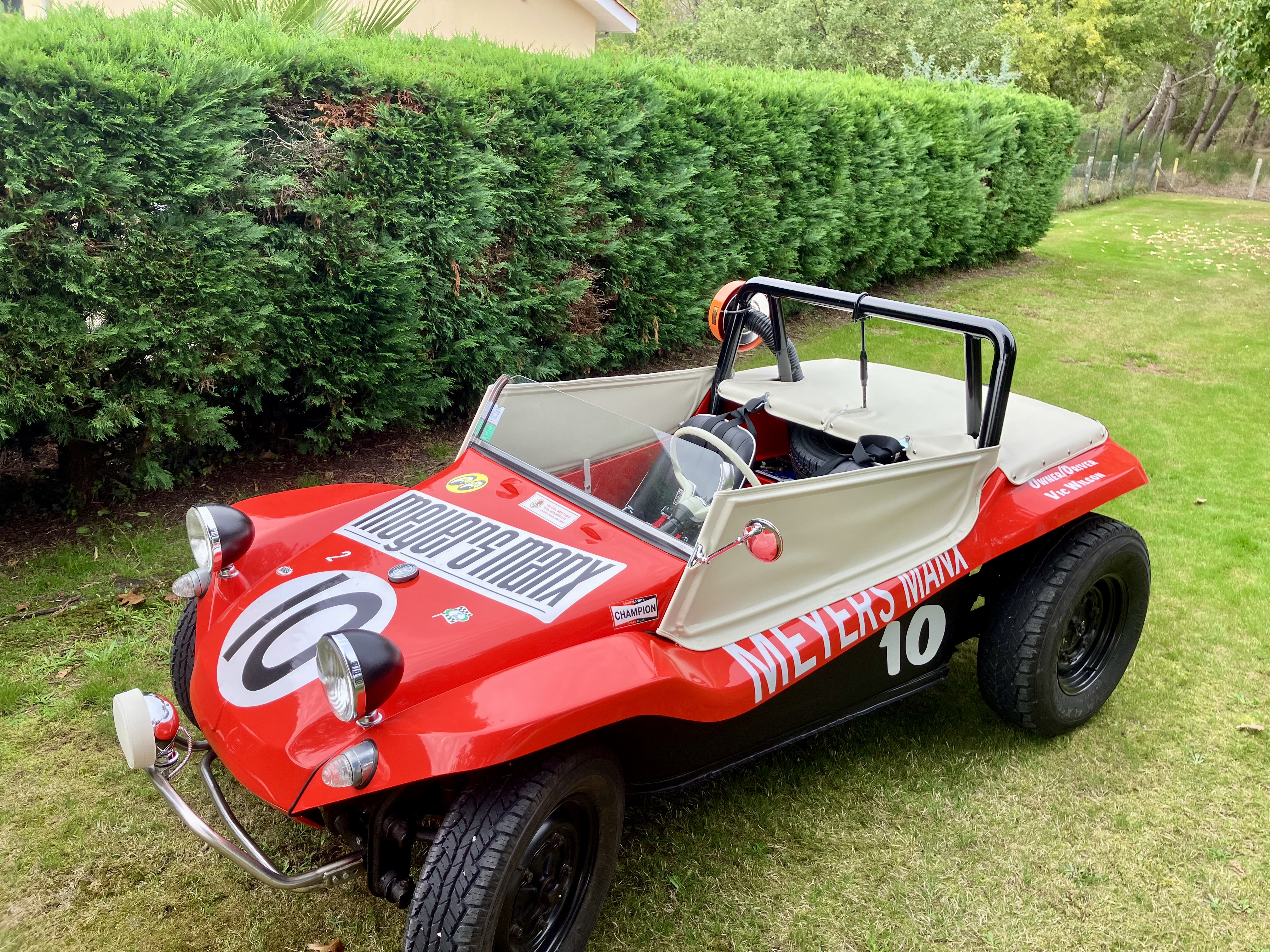
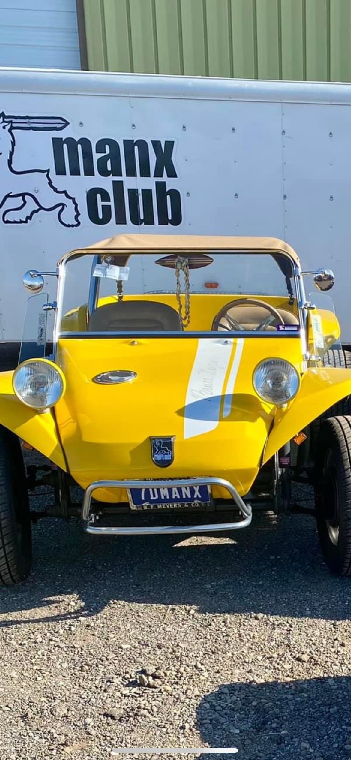
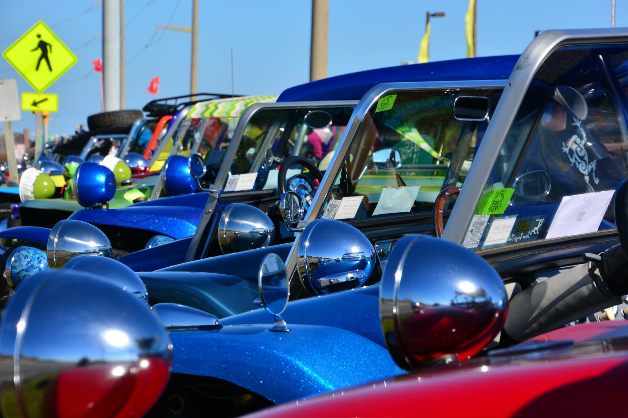
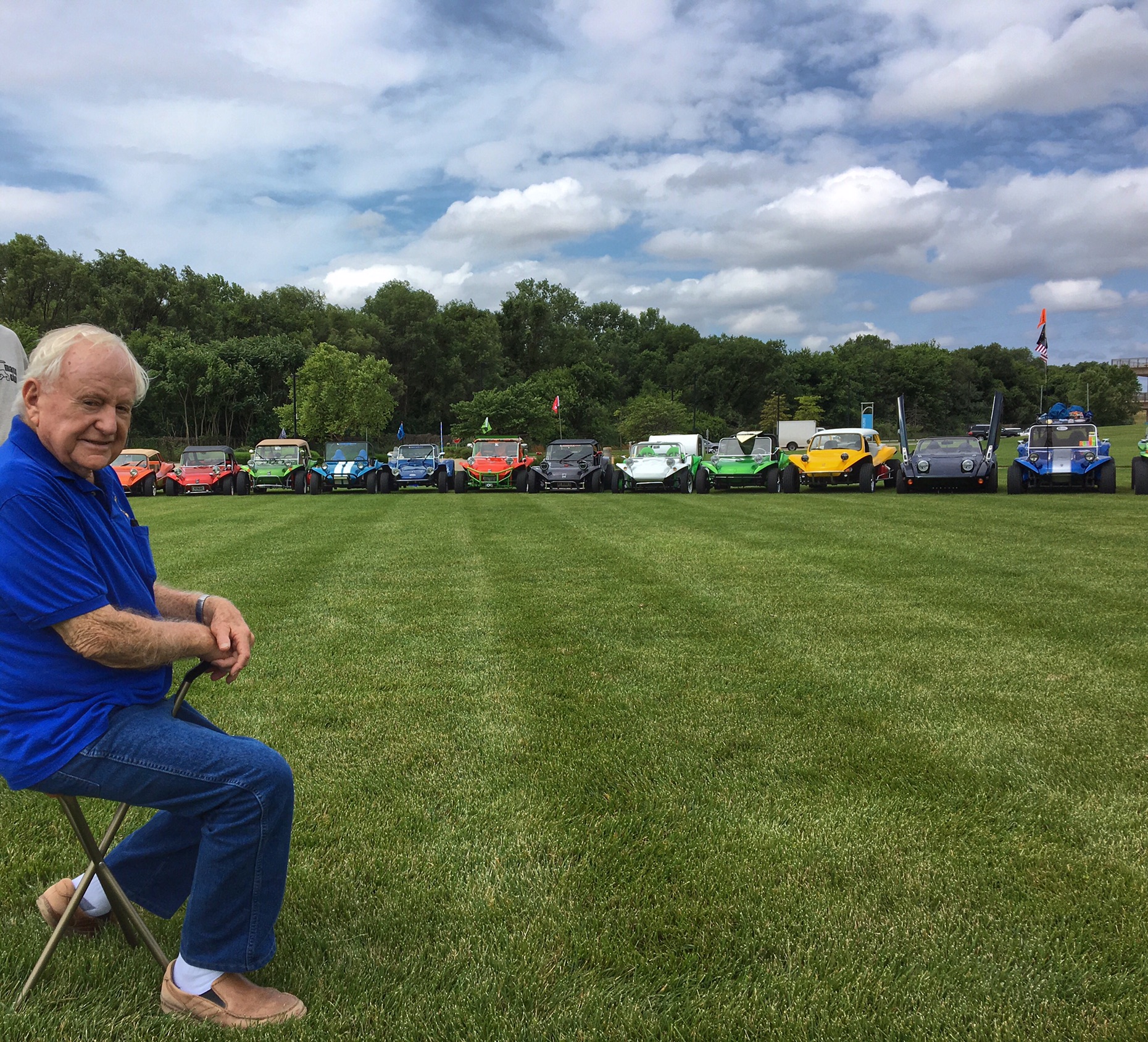
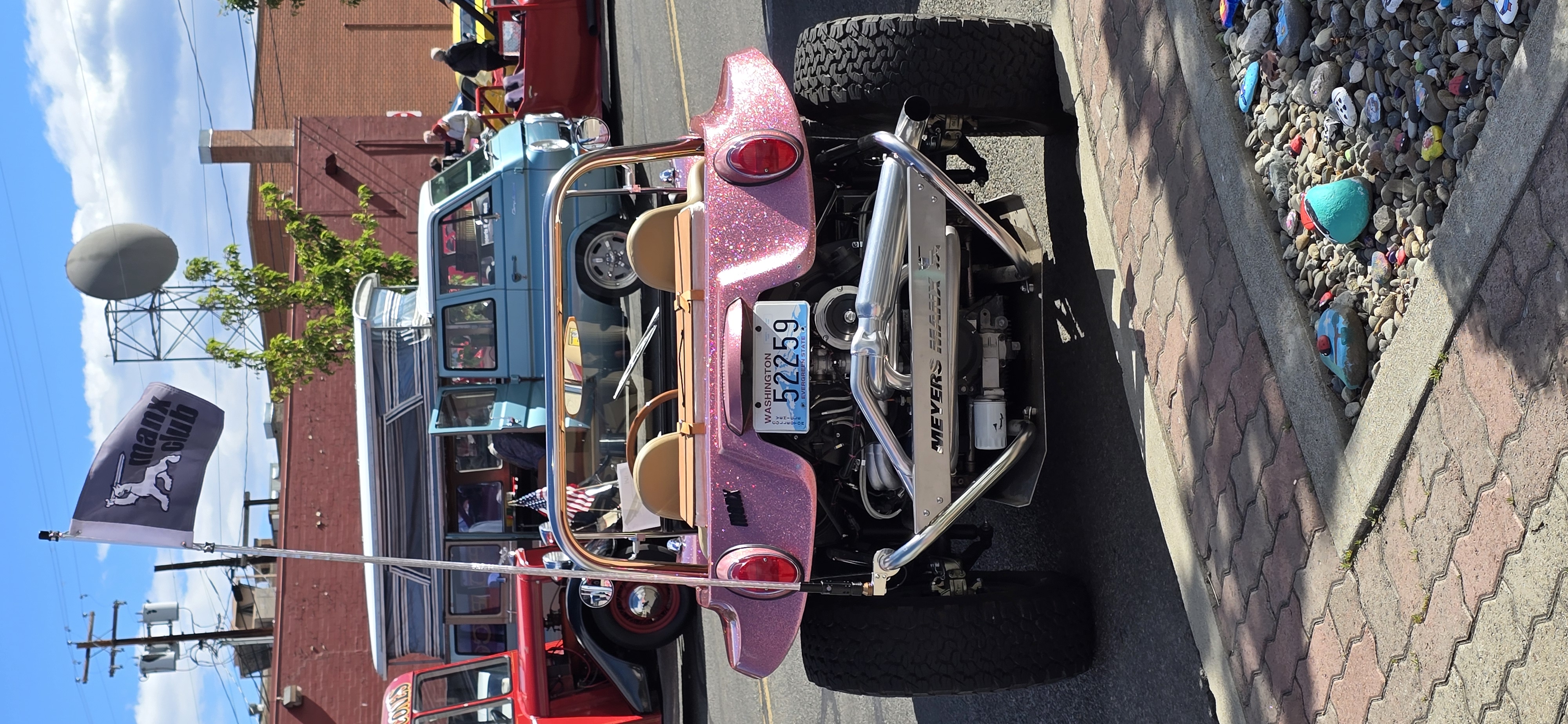
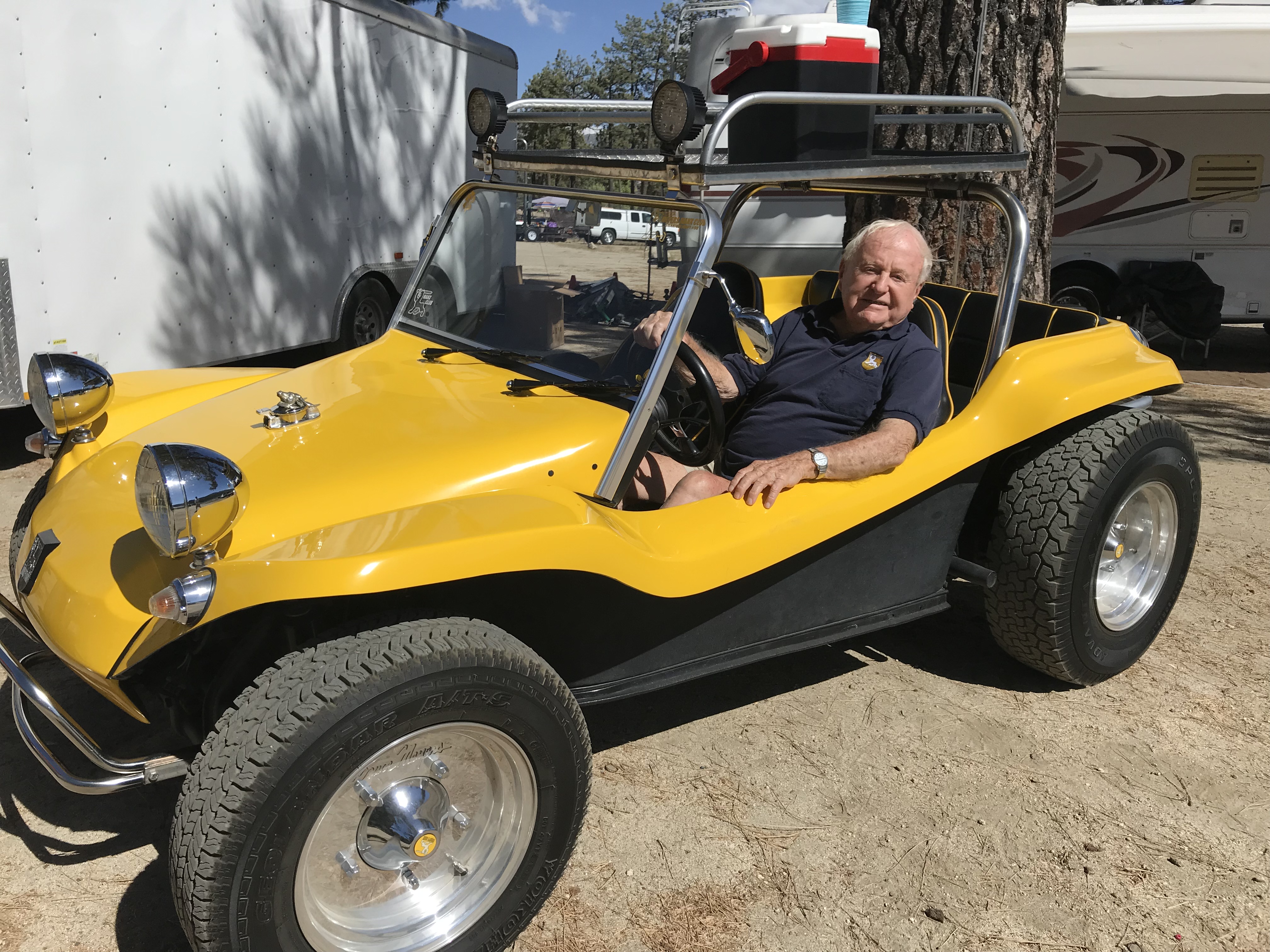
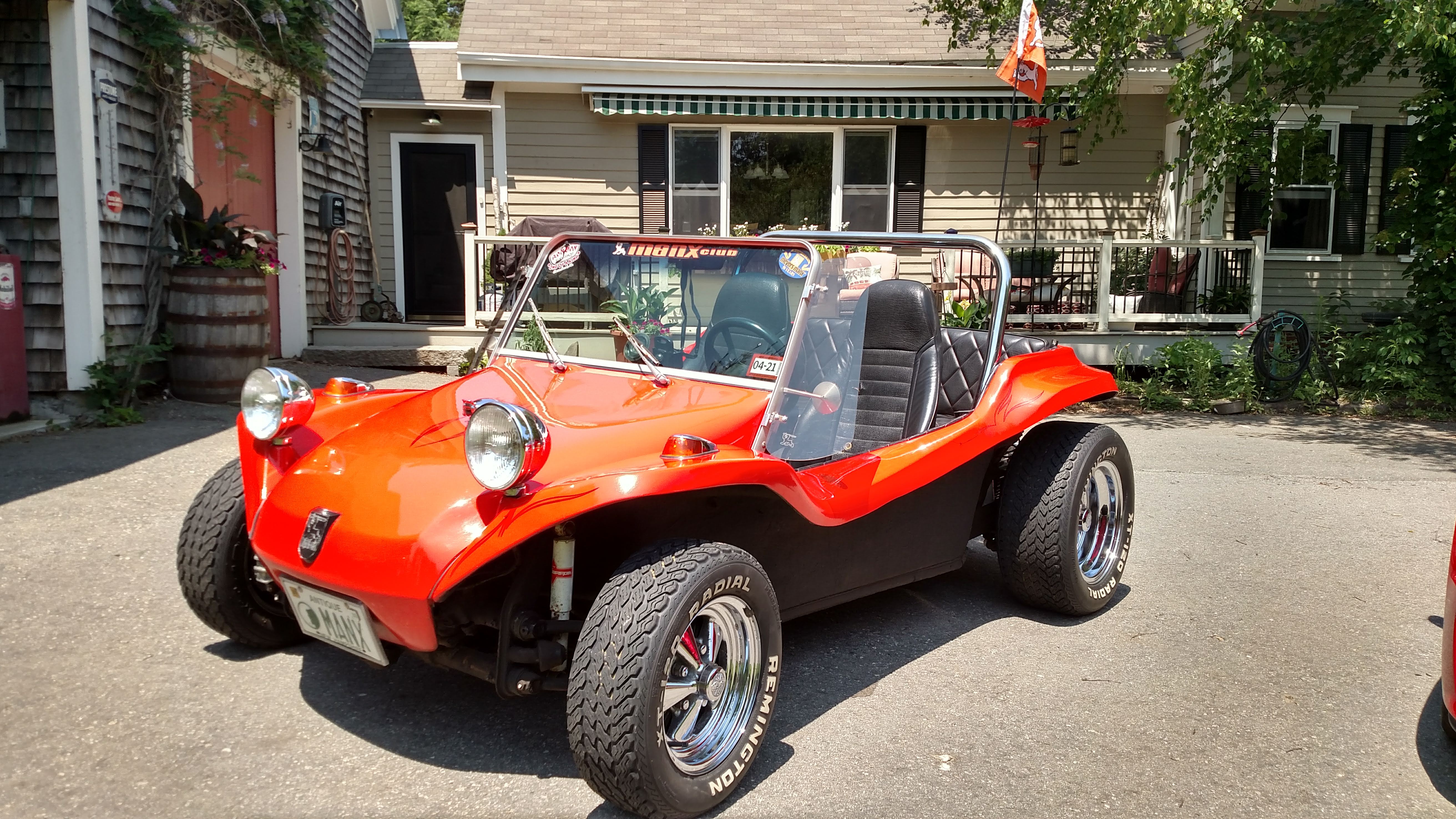
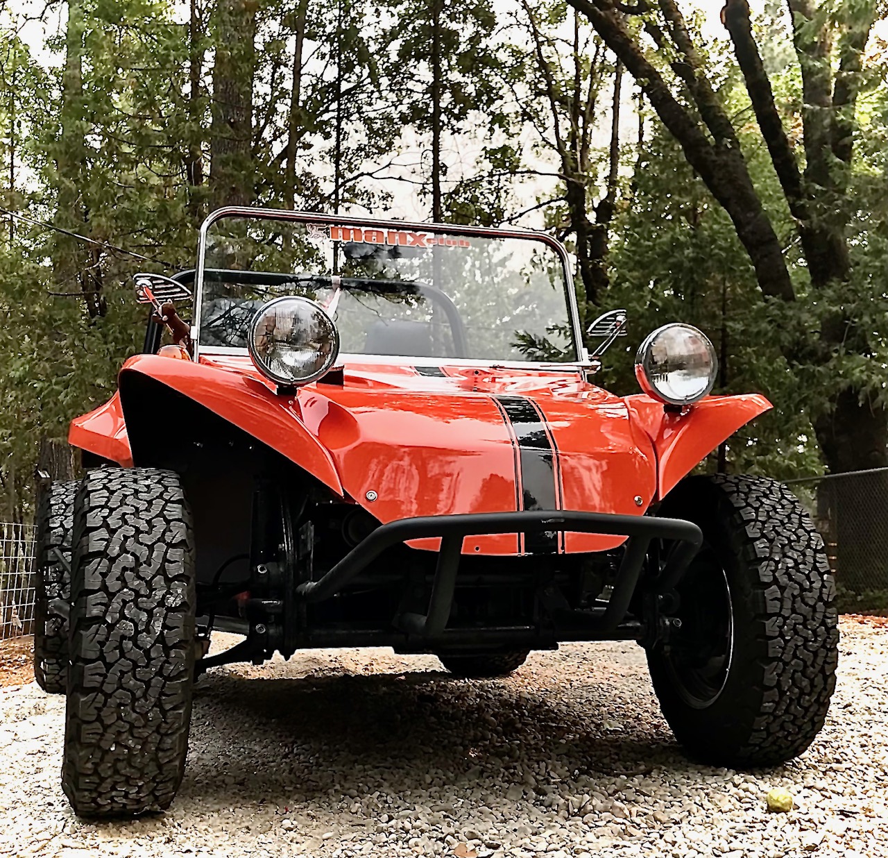
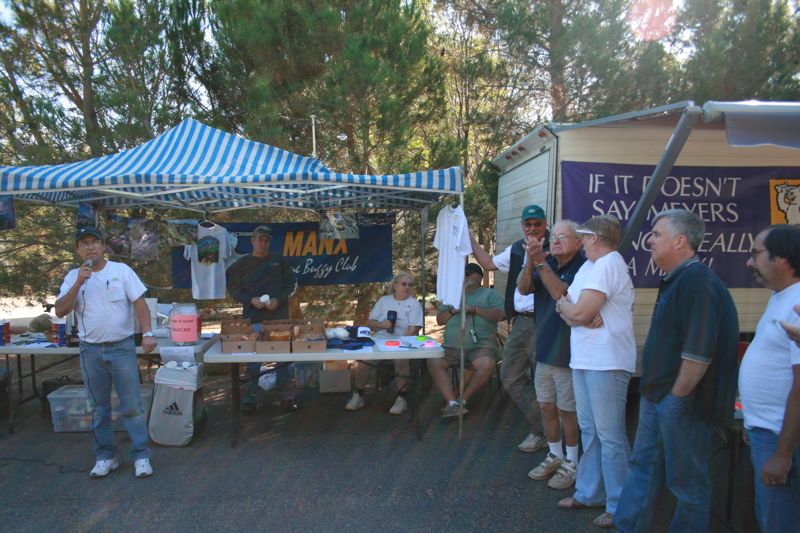
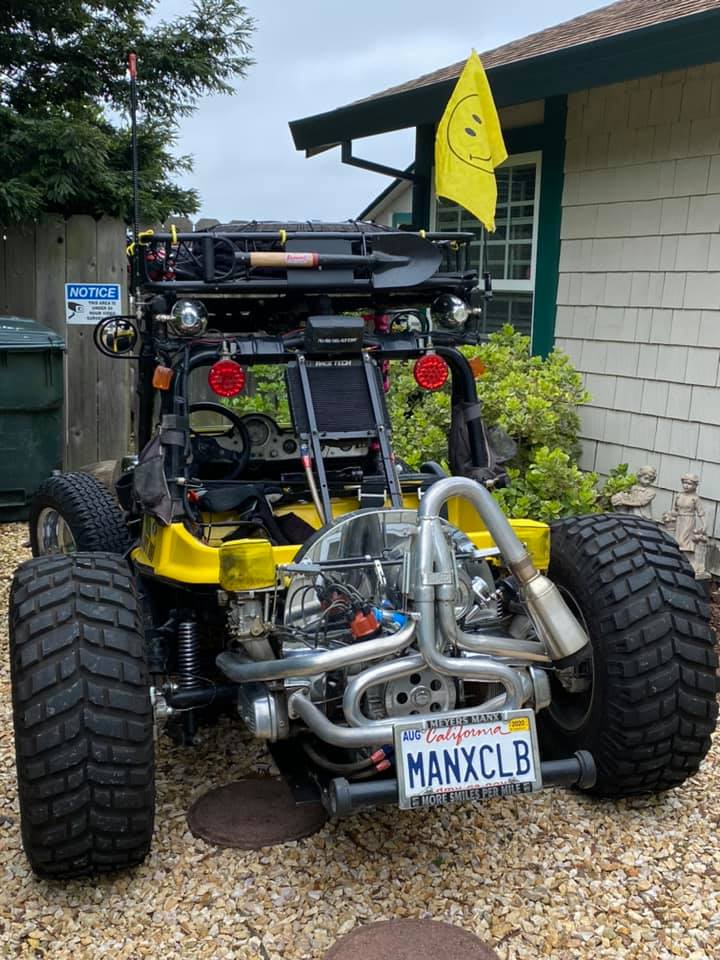
The original Meyers Manx community — since the beginning.
Join the Club →
The original Meyers Manx community — since the beginning.
Join the Club →
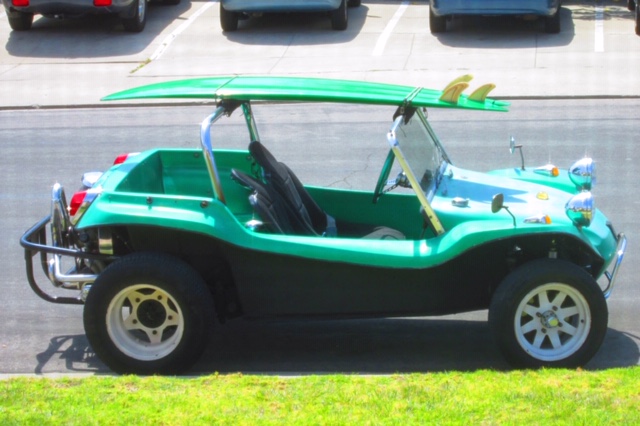
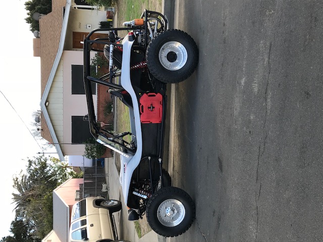
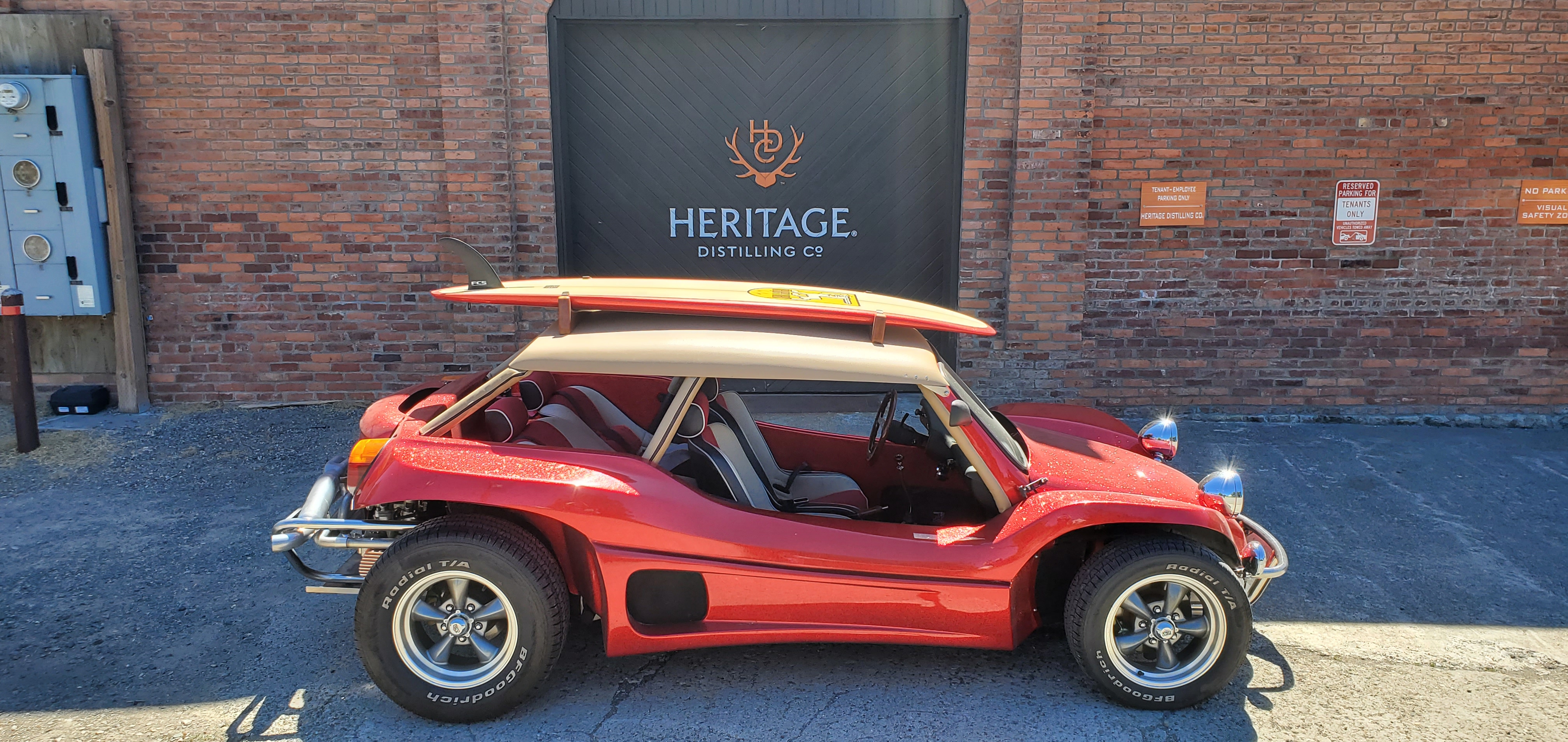
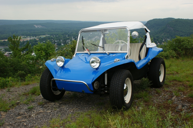
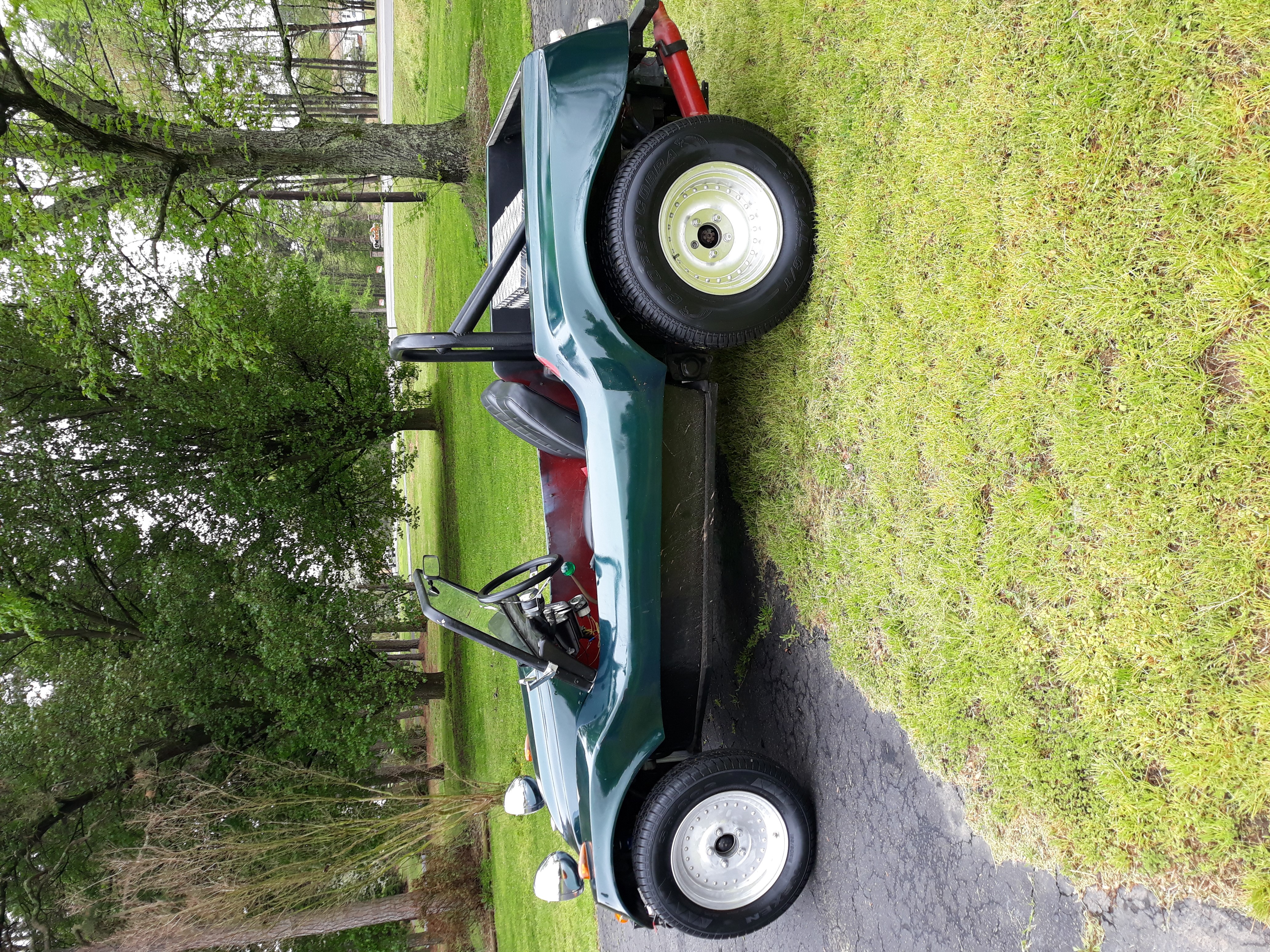
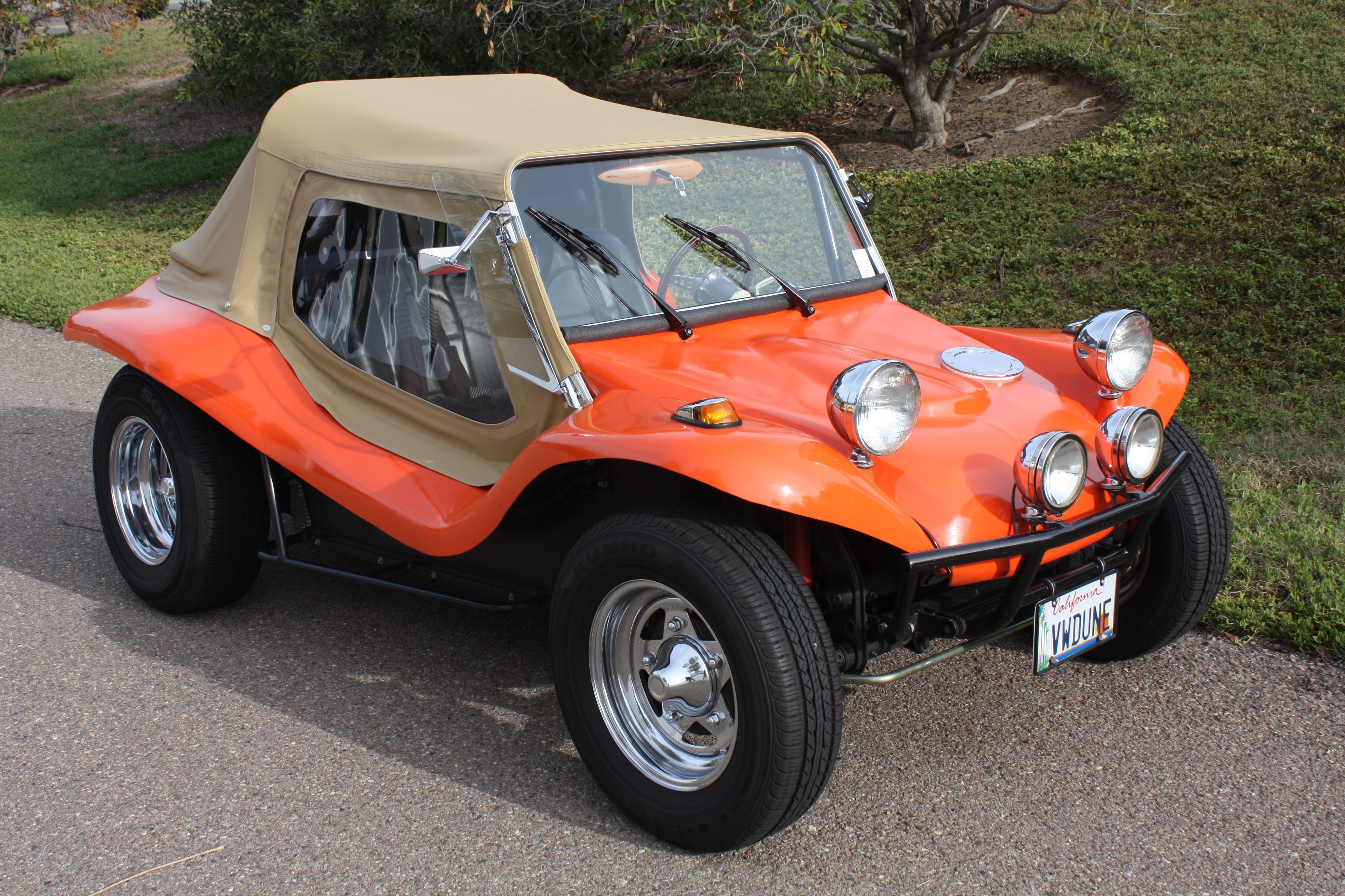
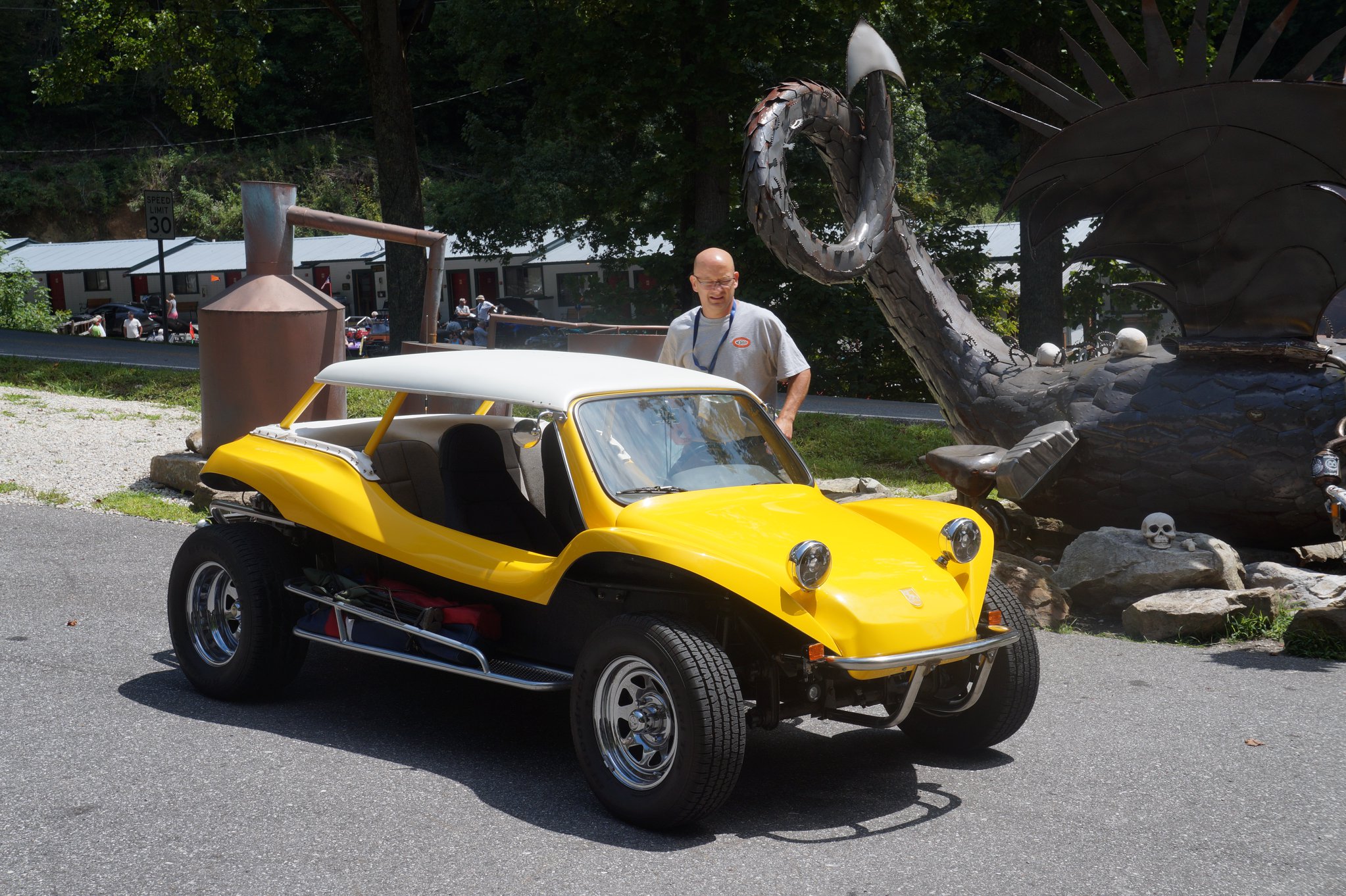
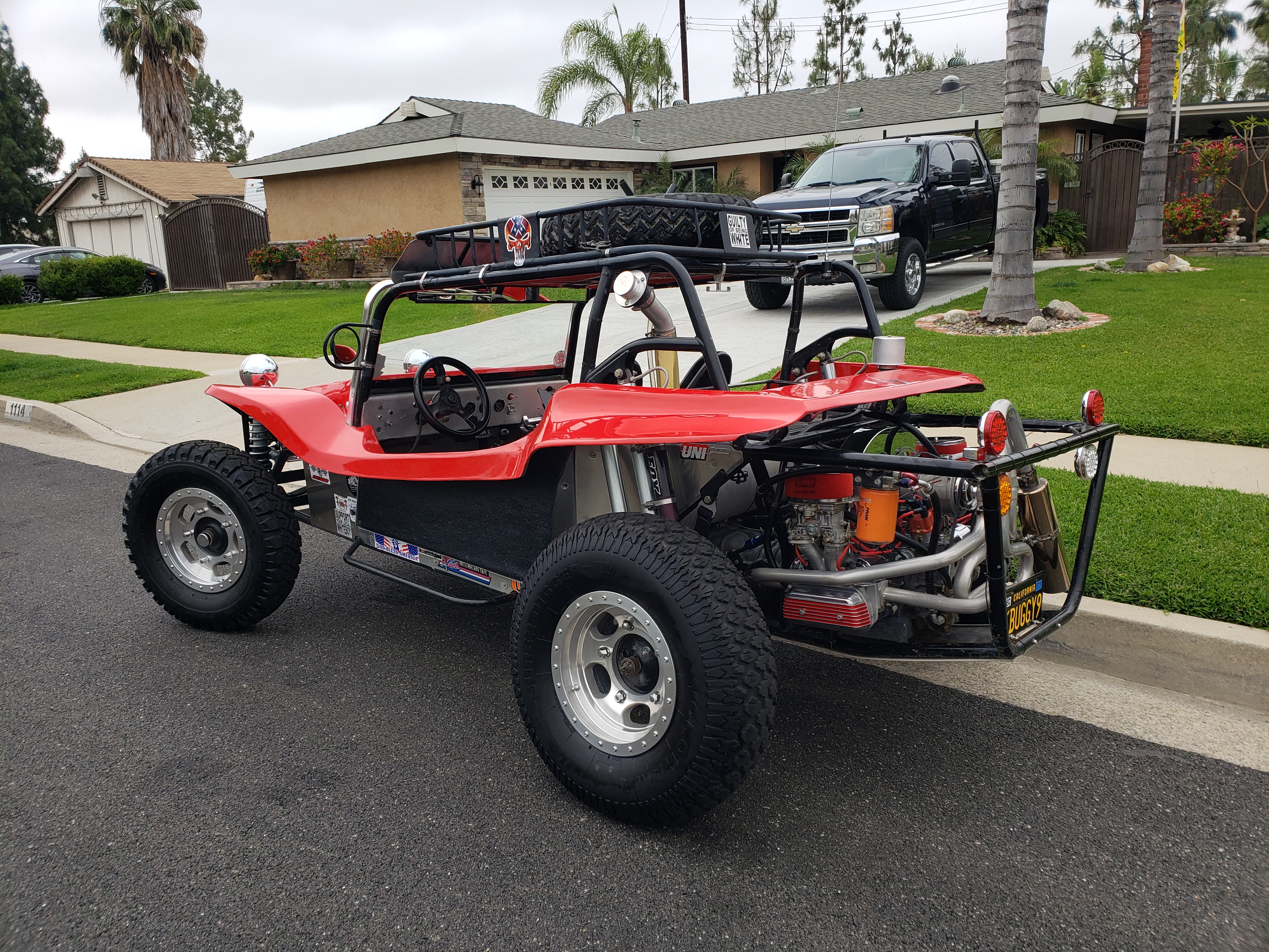
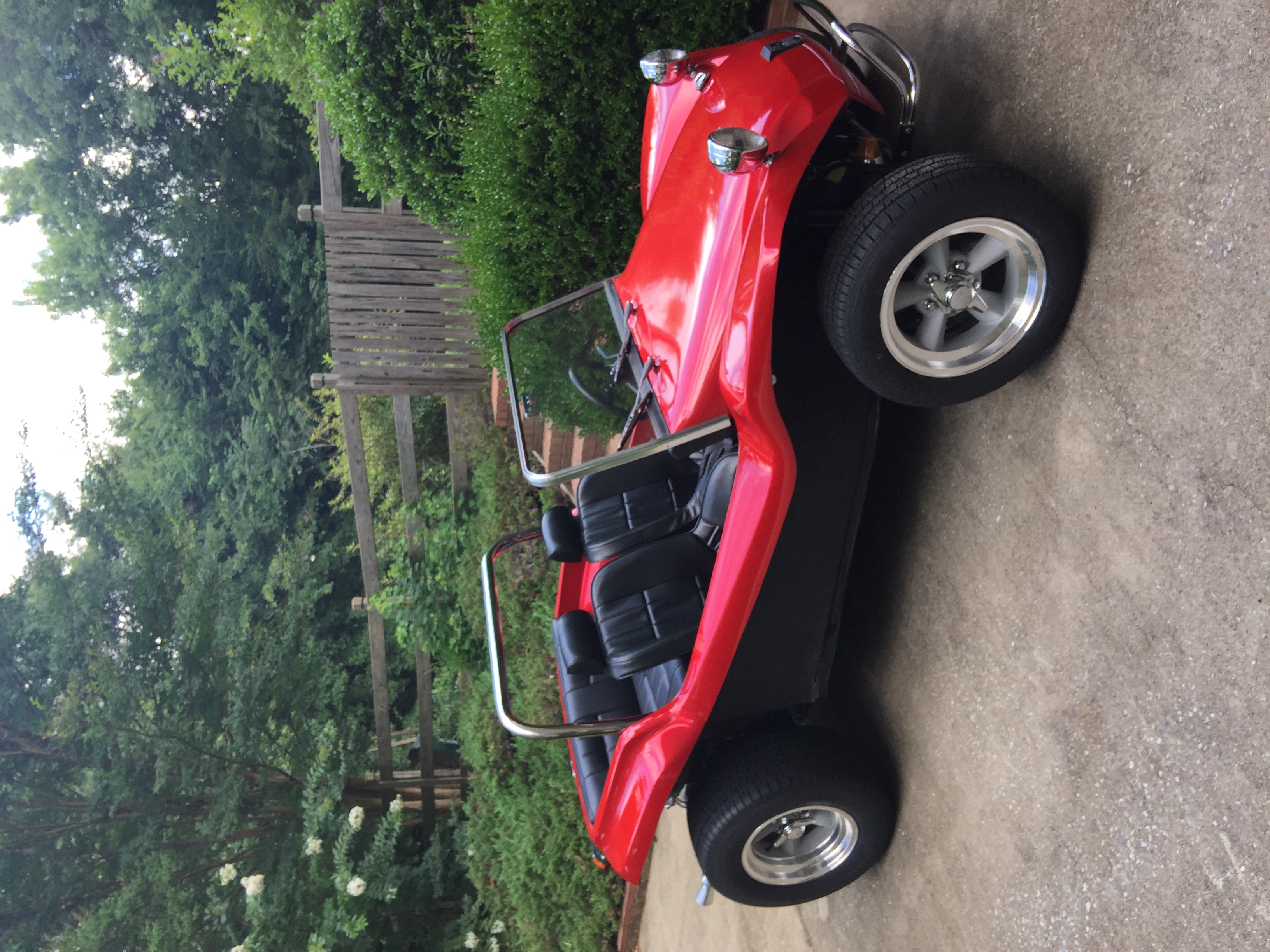
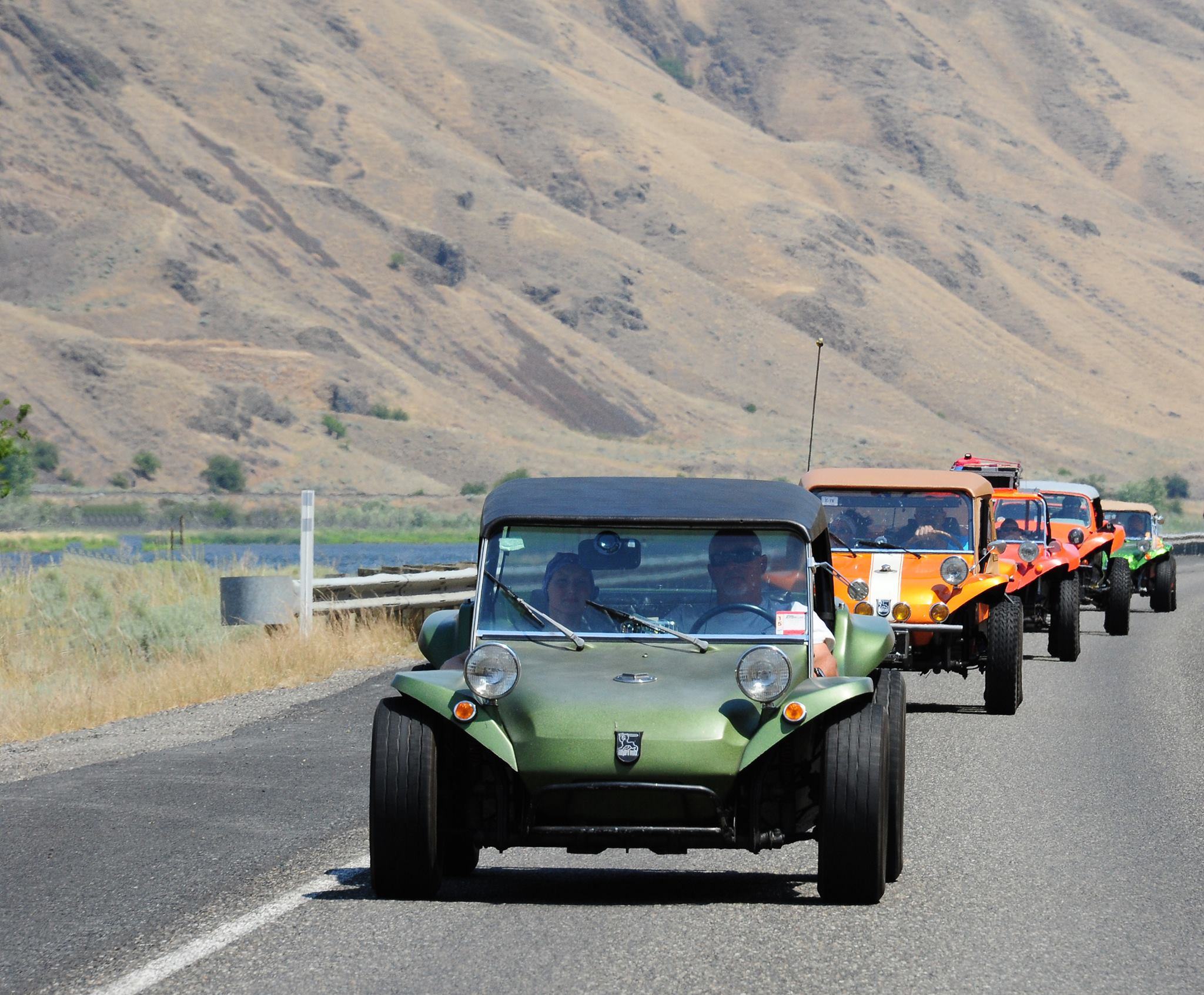
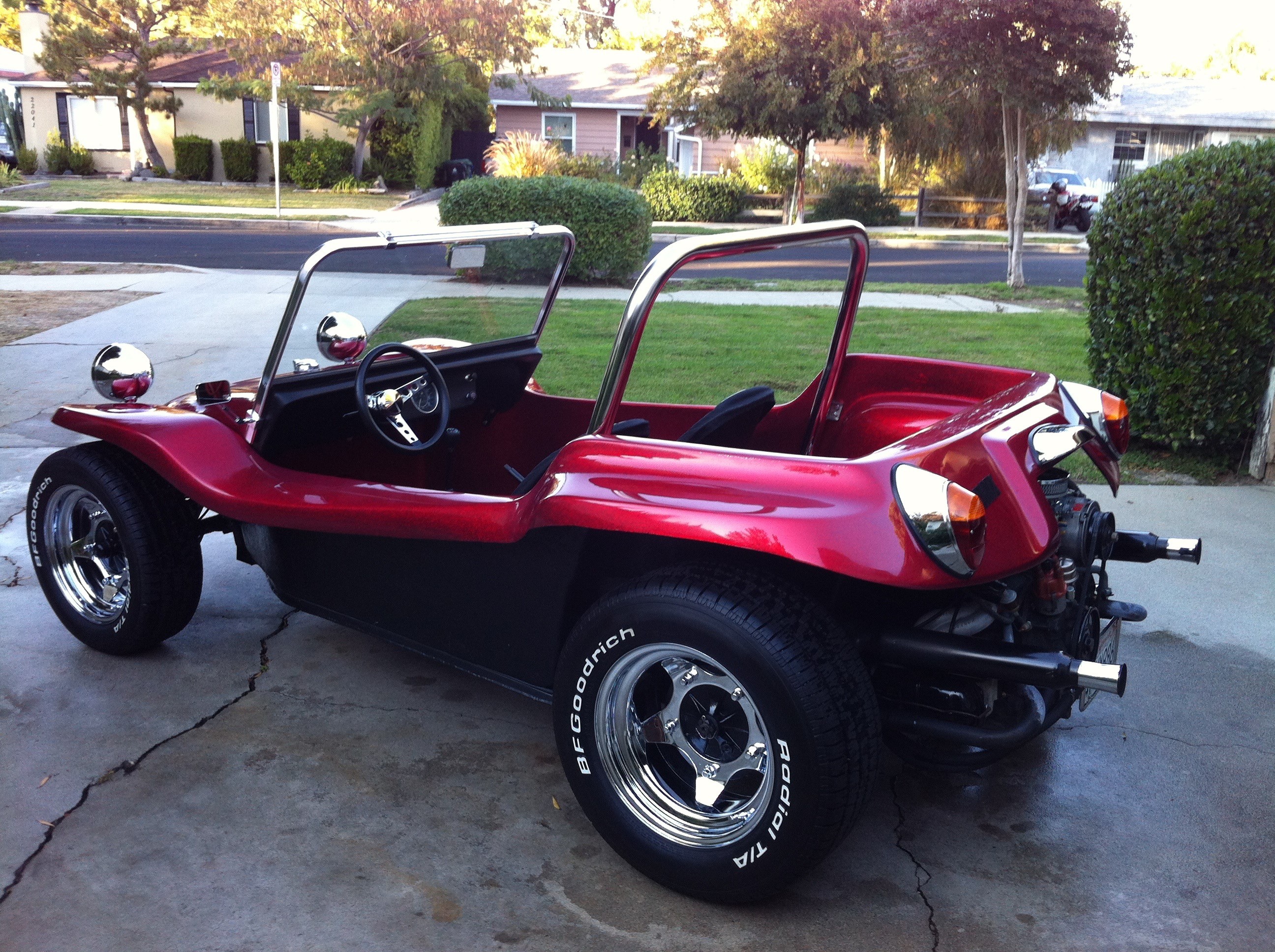
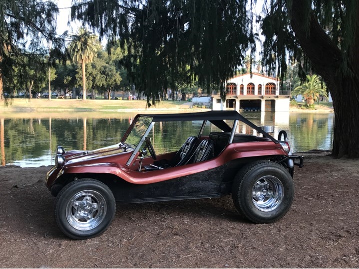
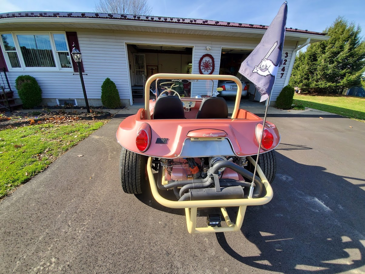
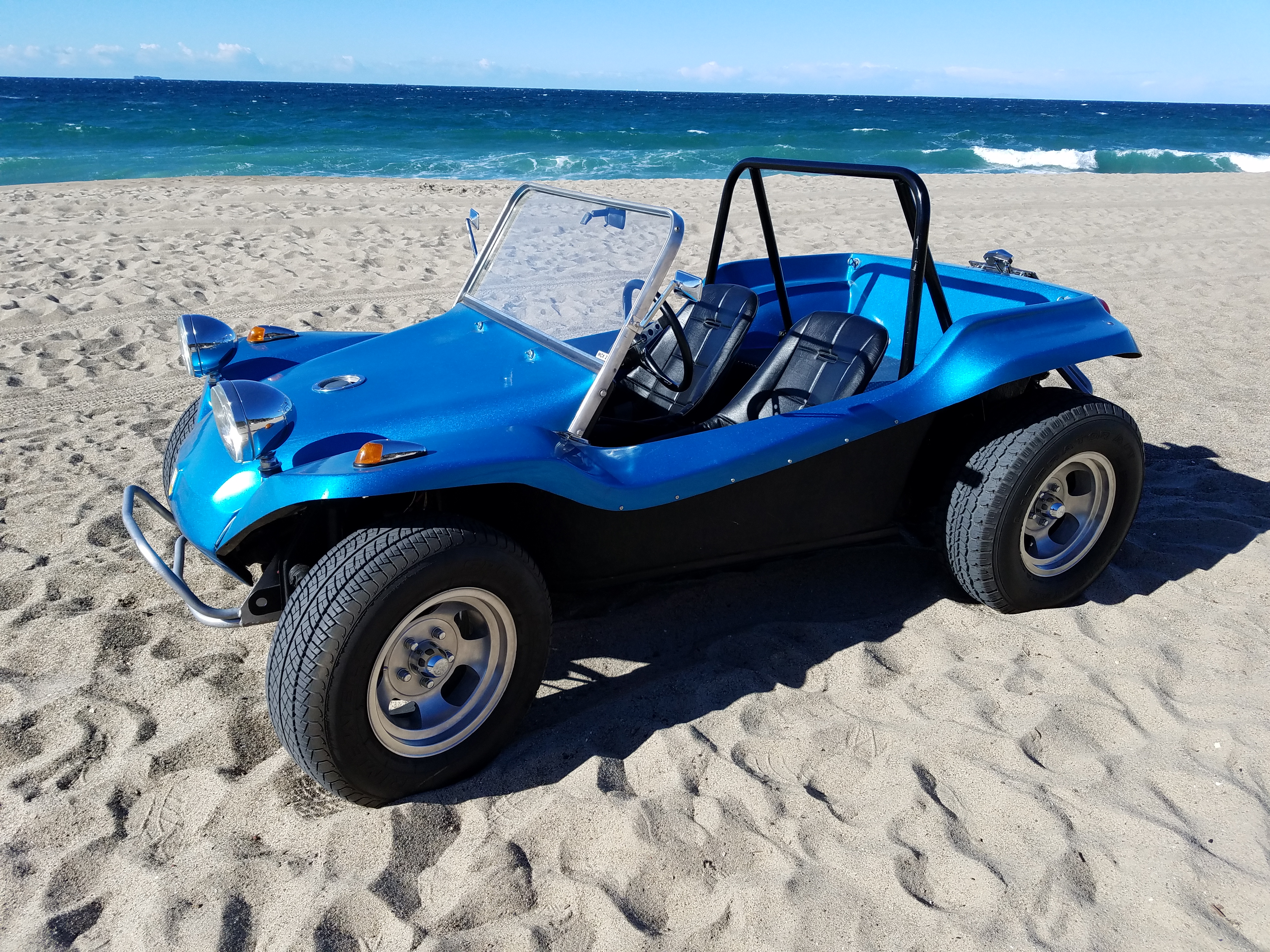
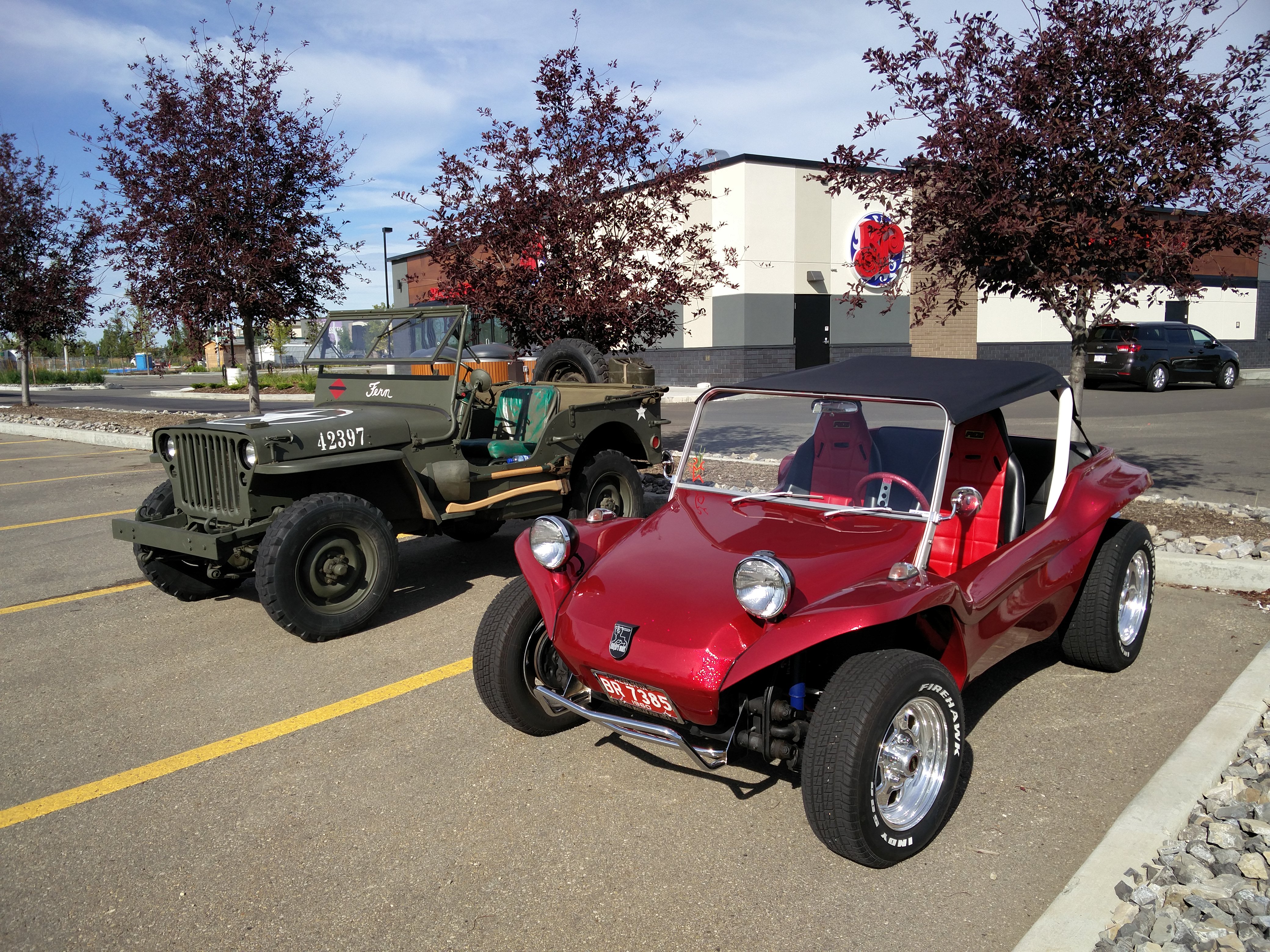
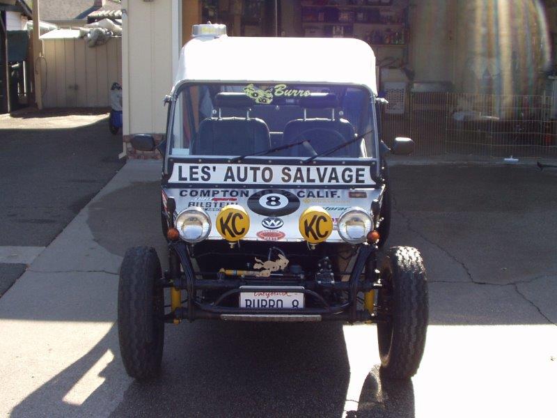
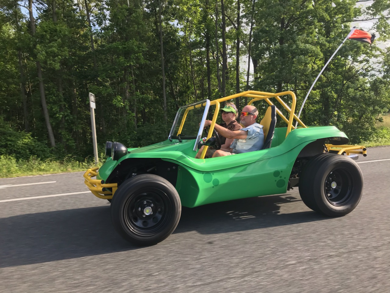
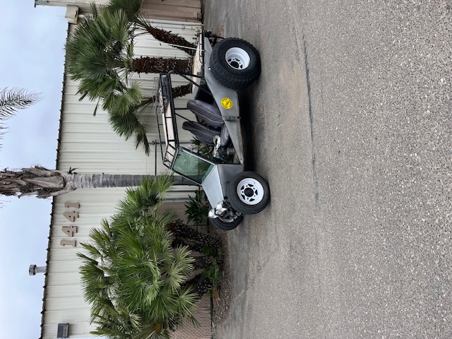
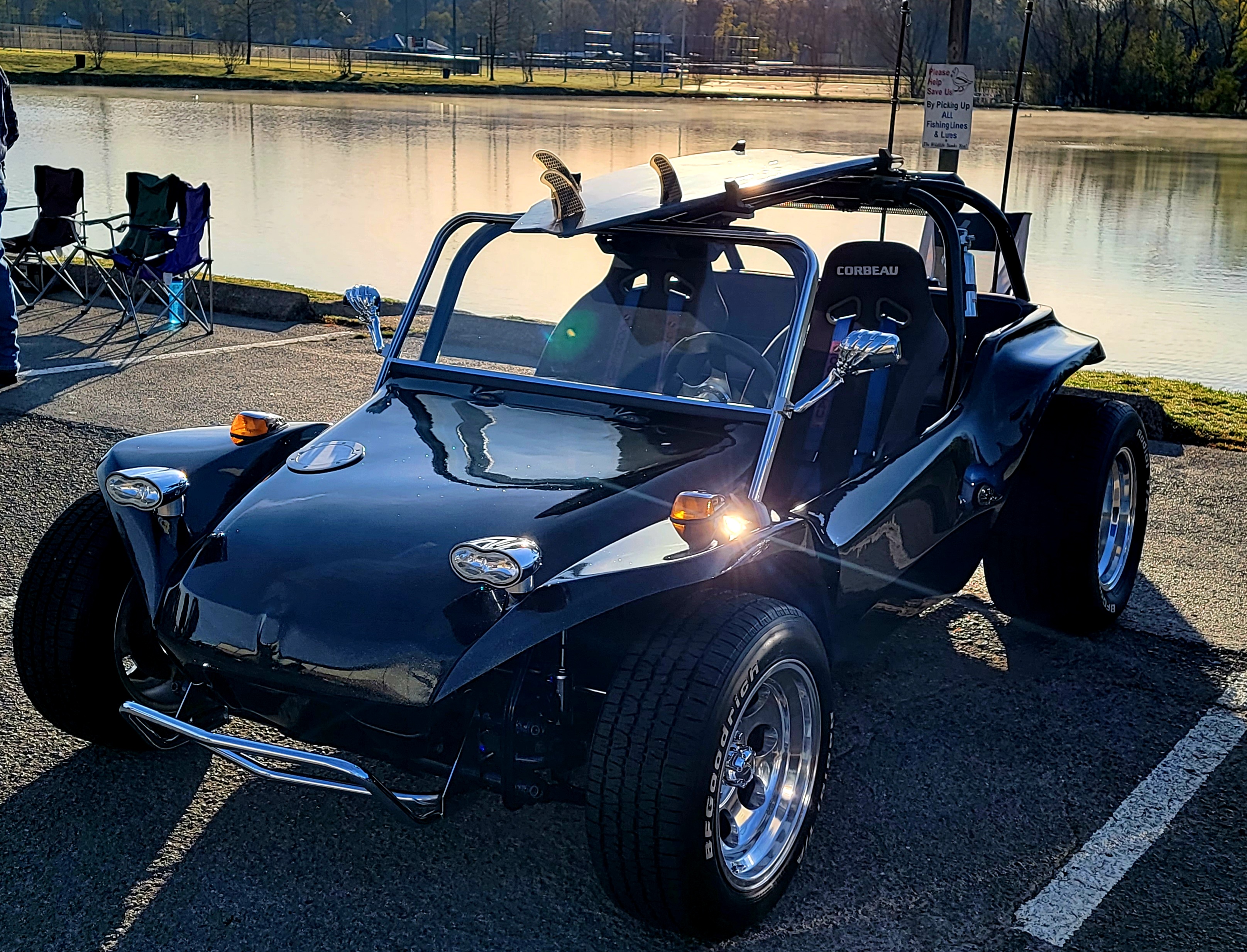
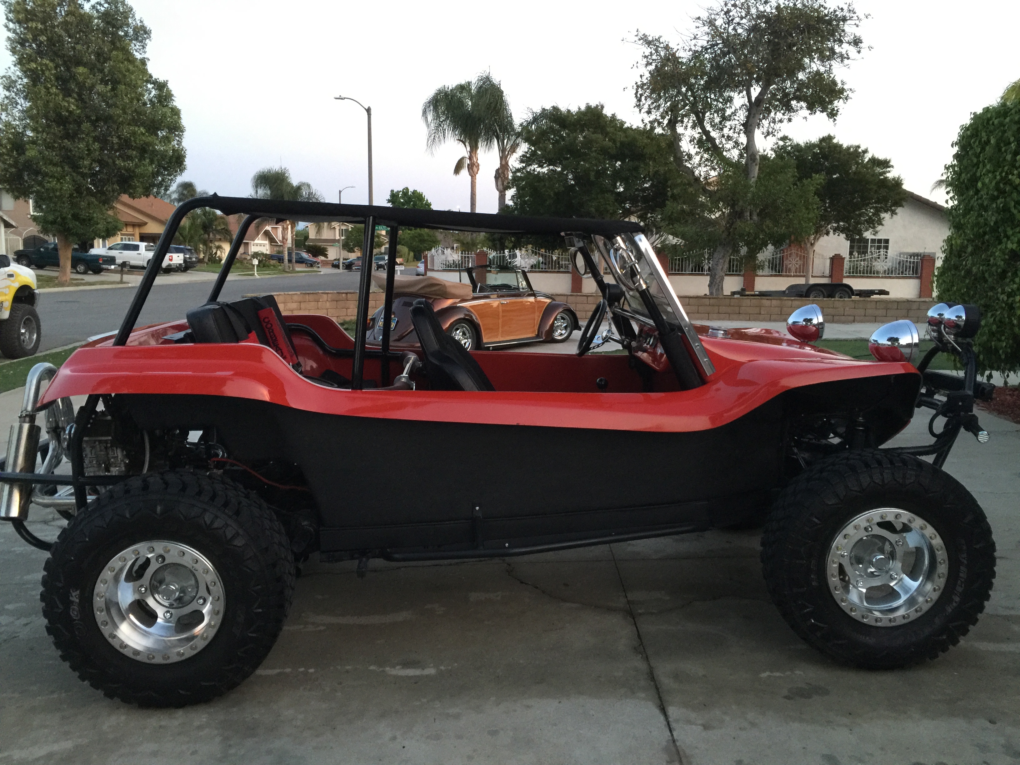
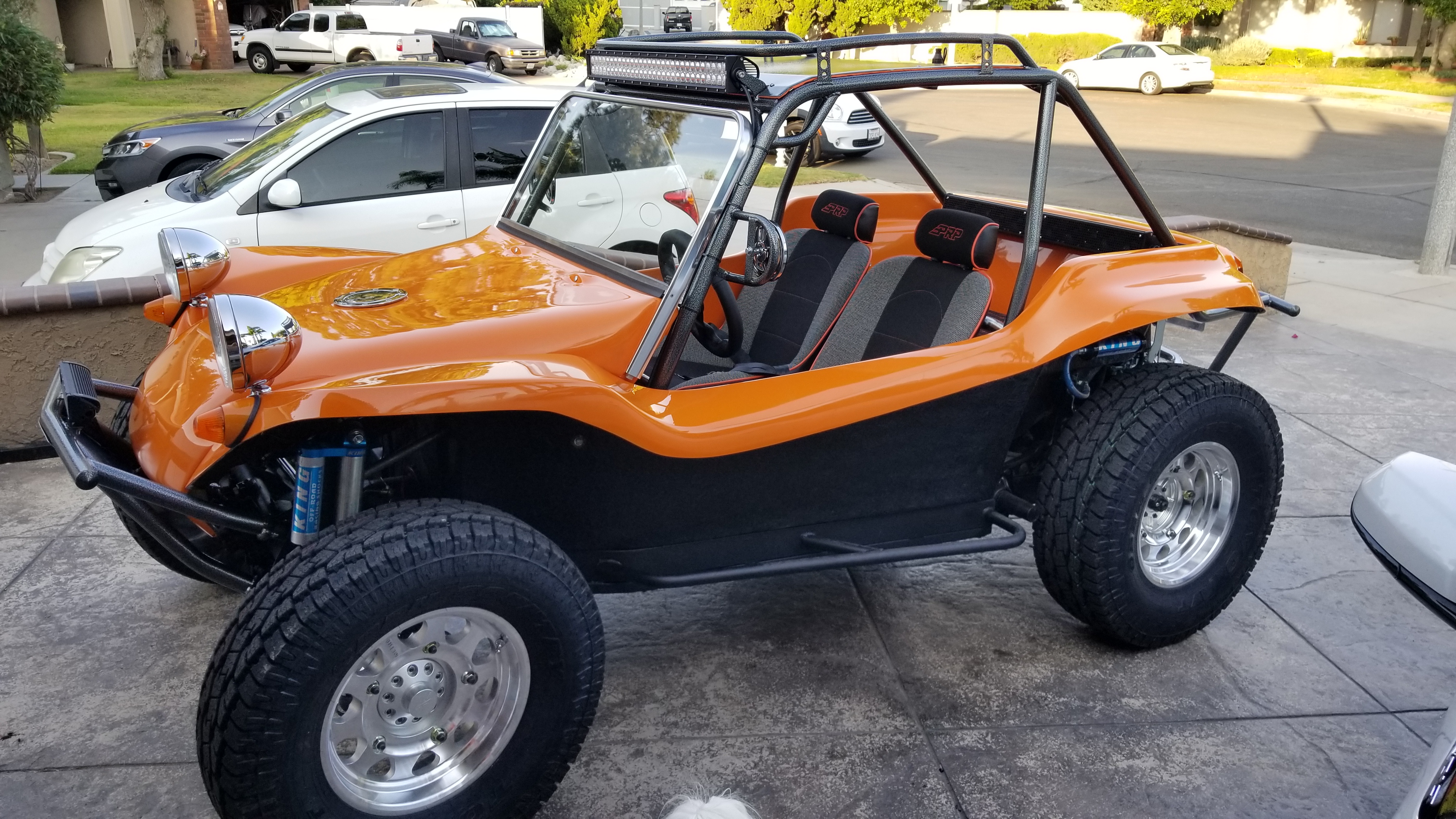
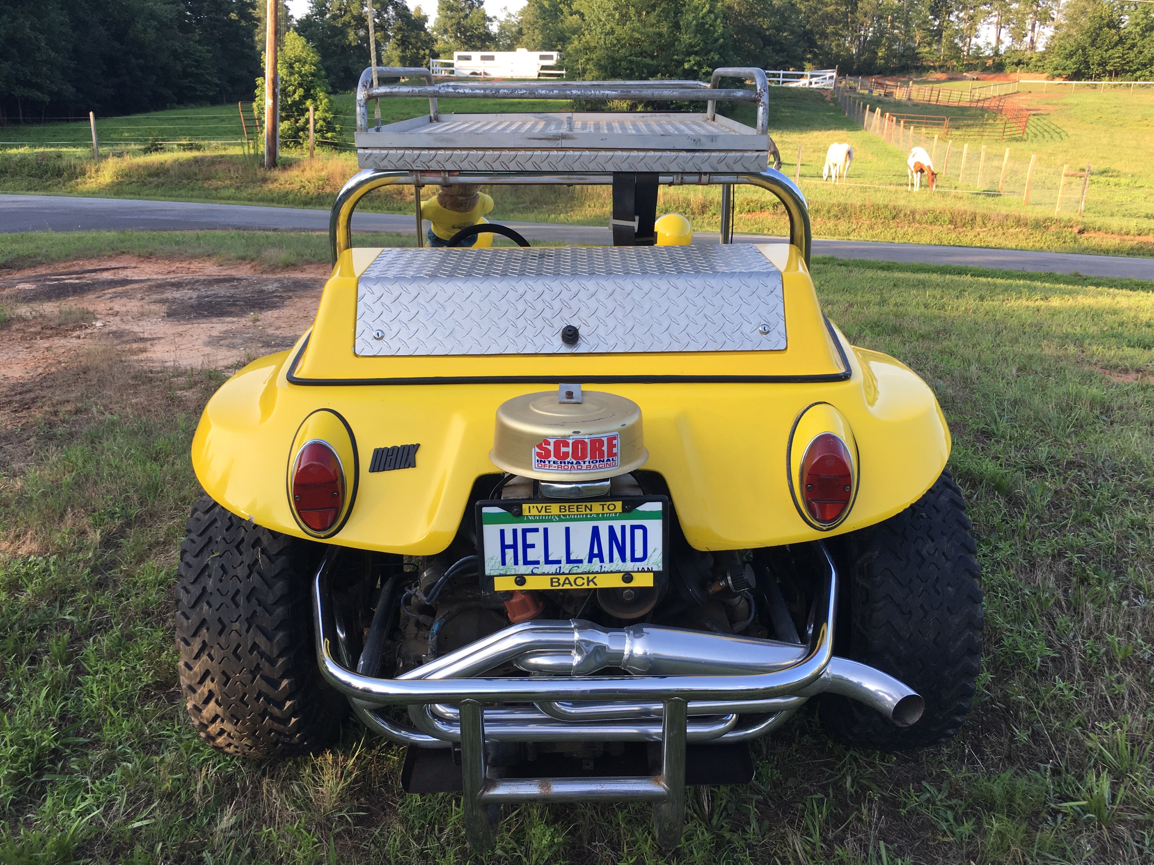
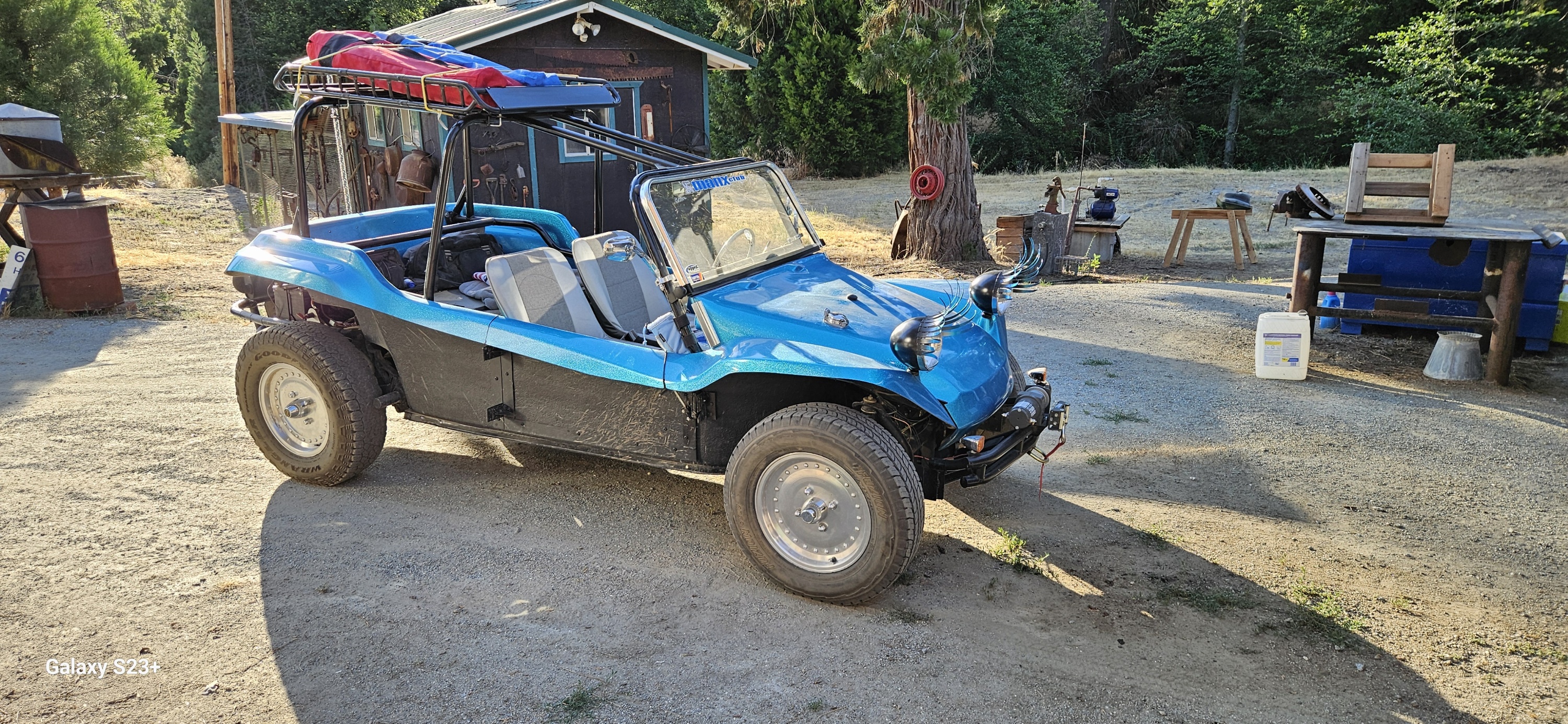
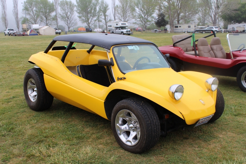
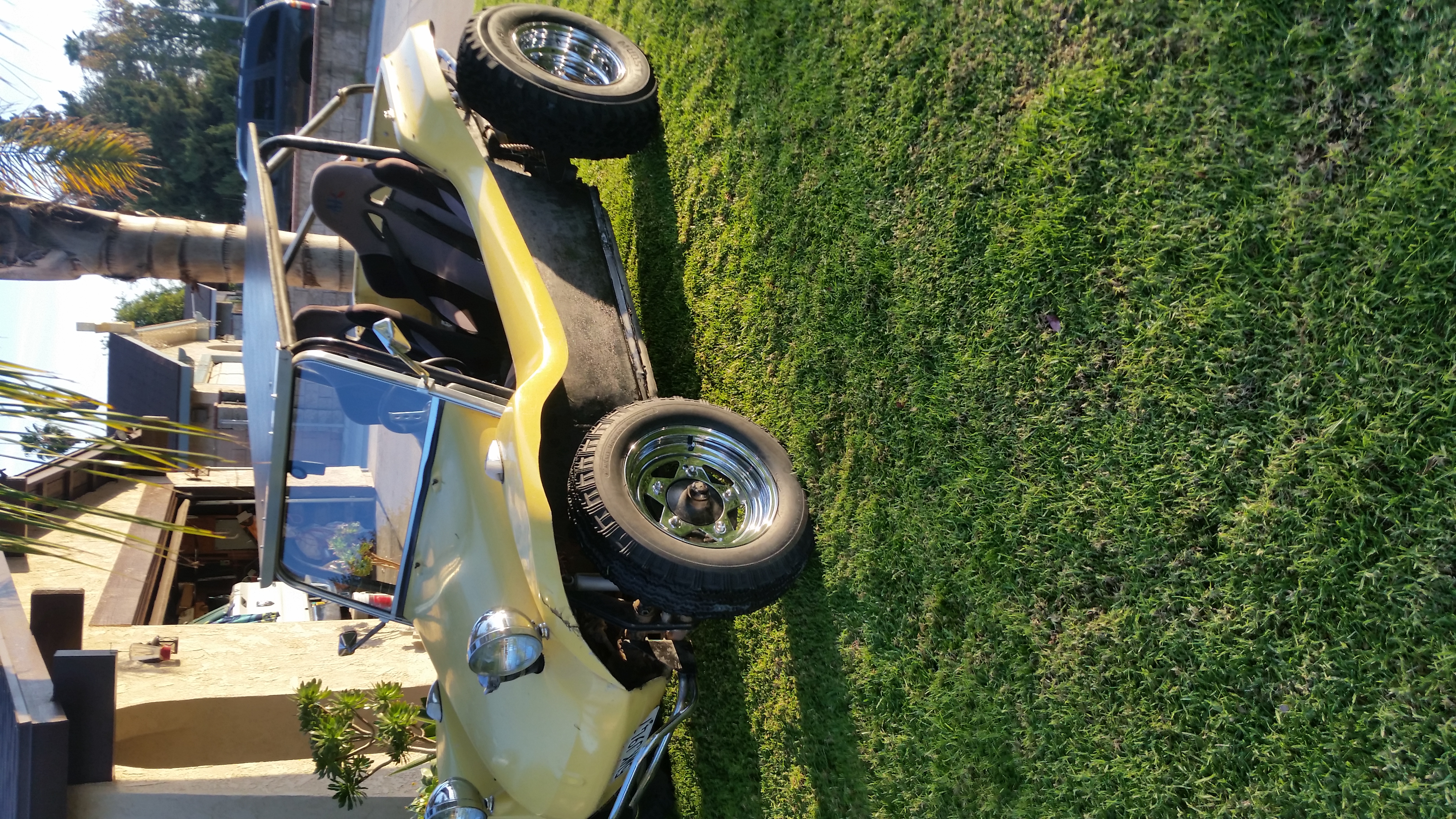
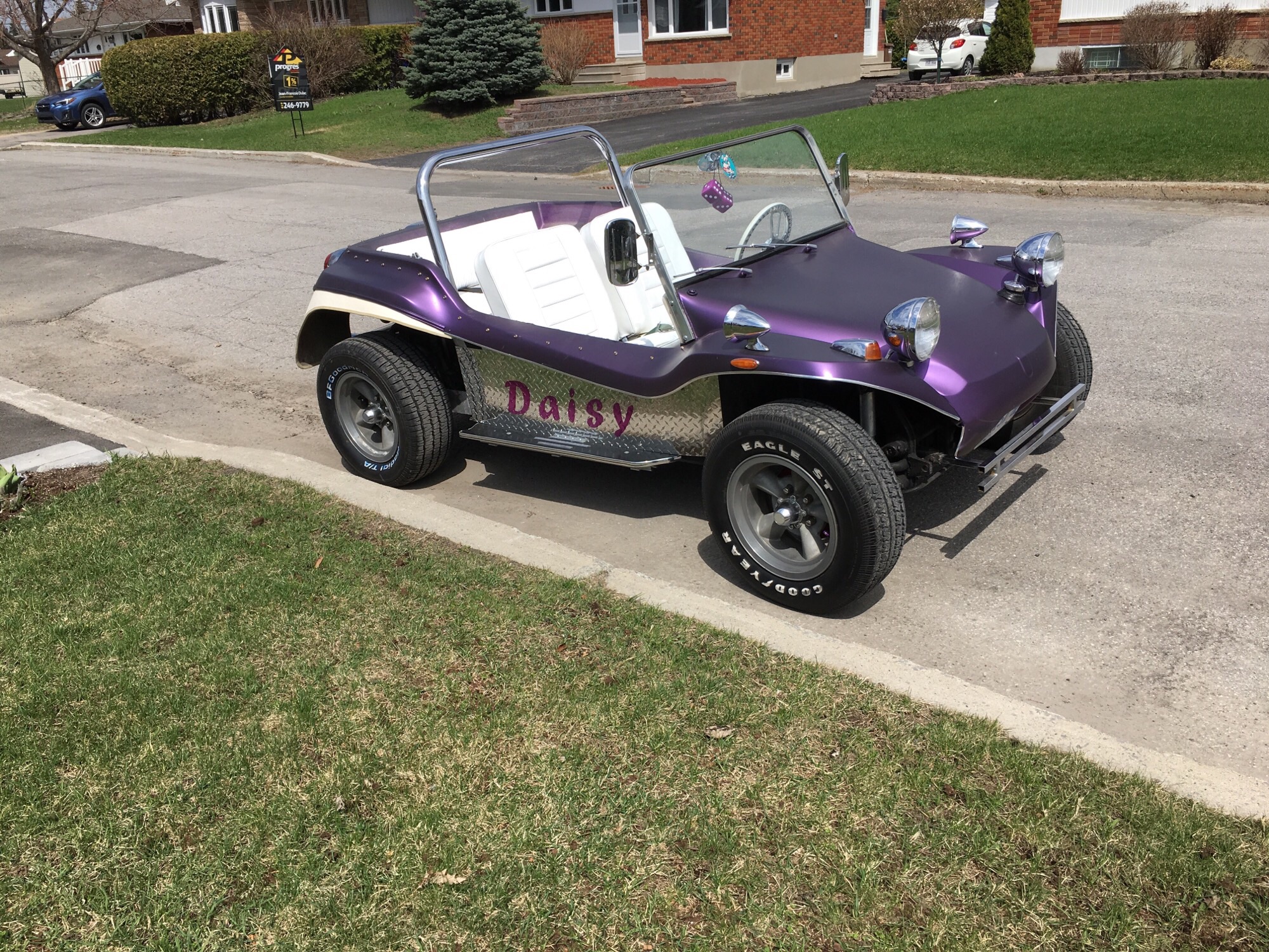
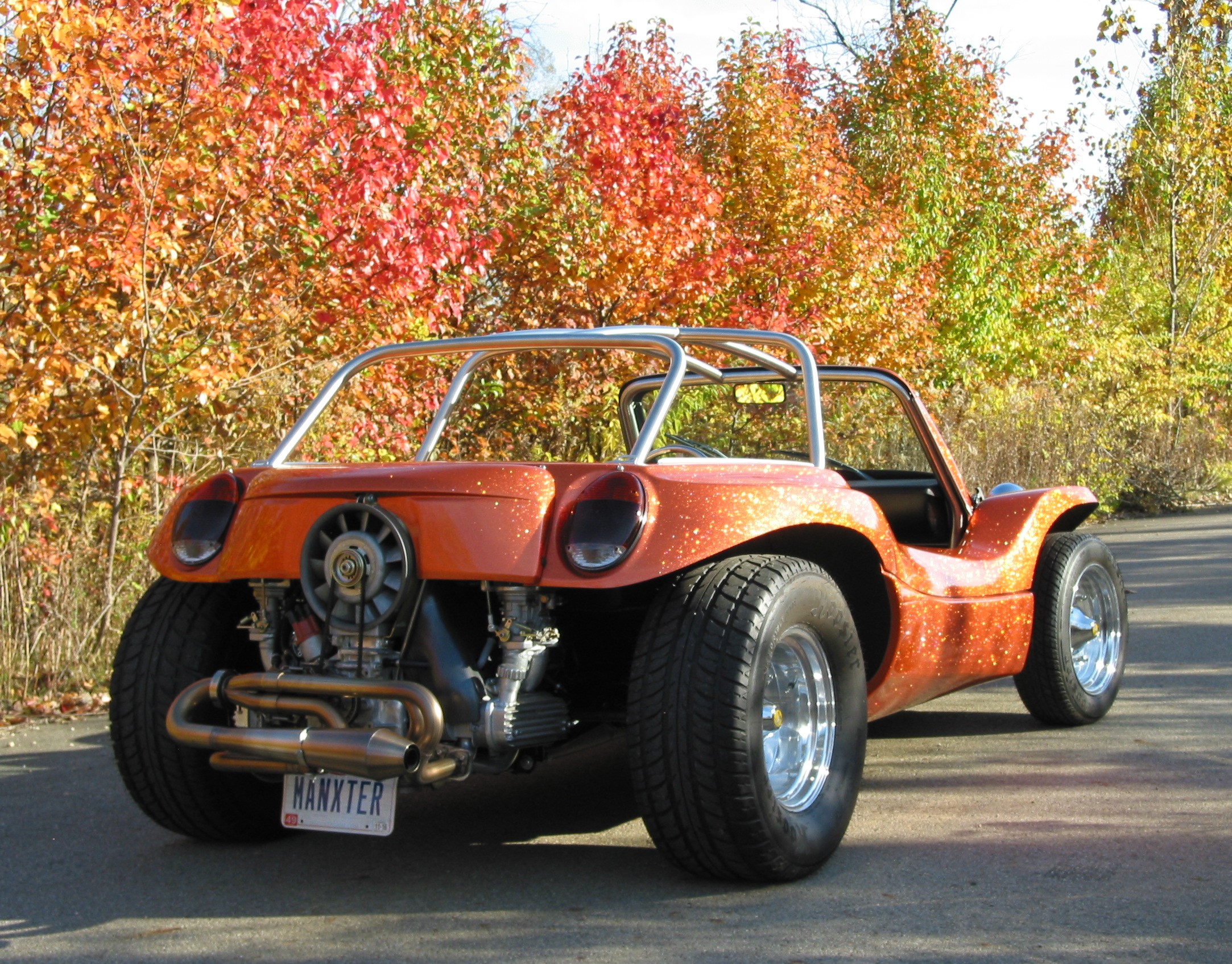
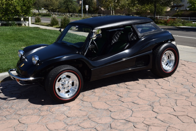
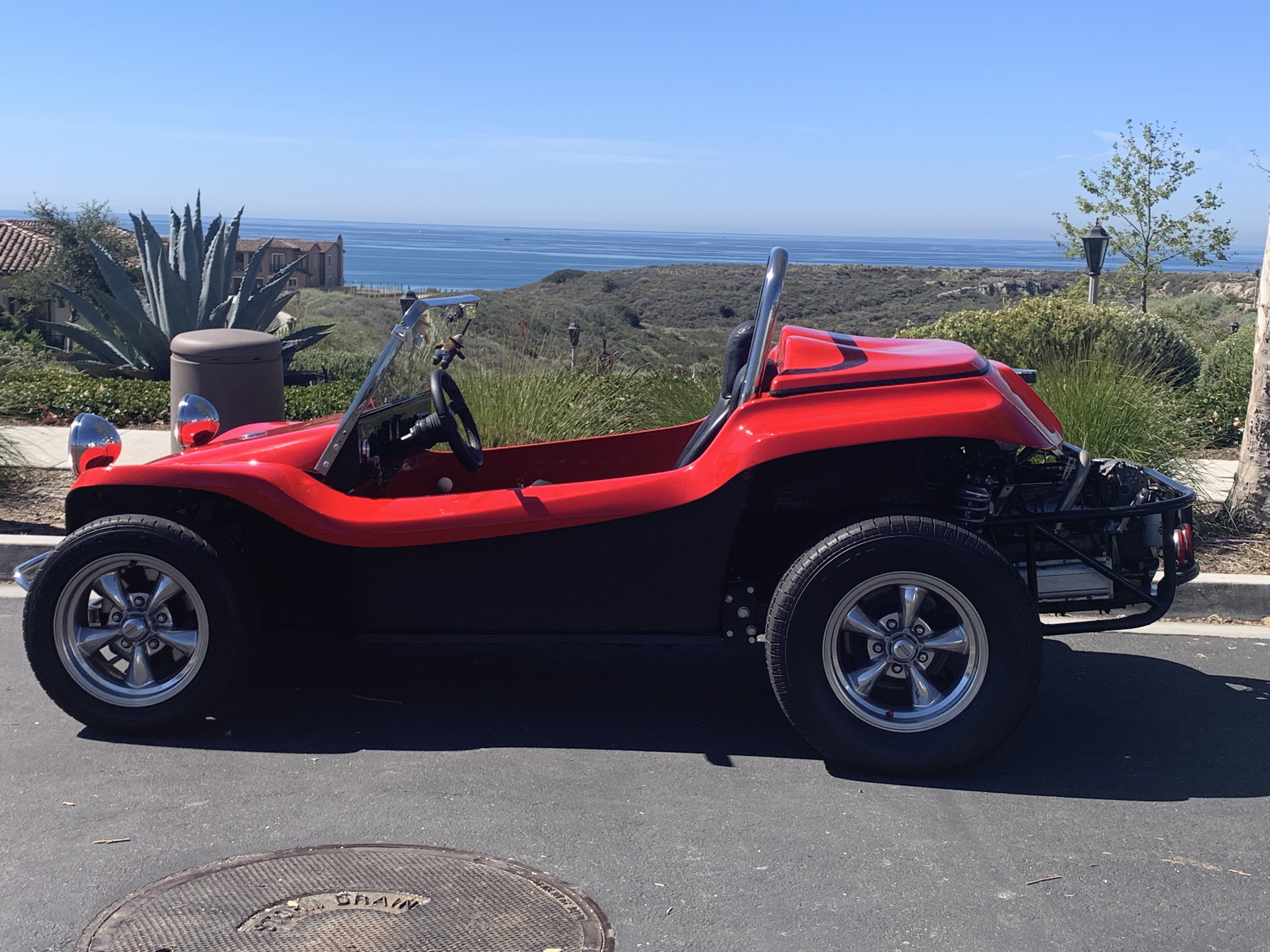
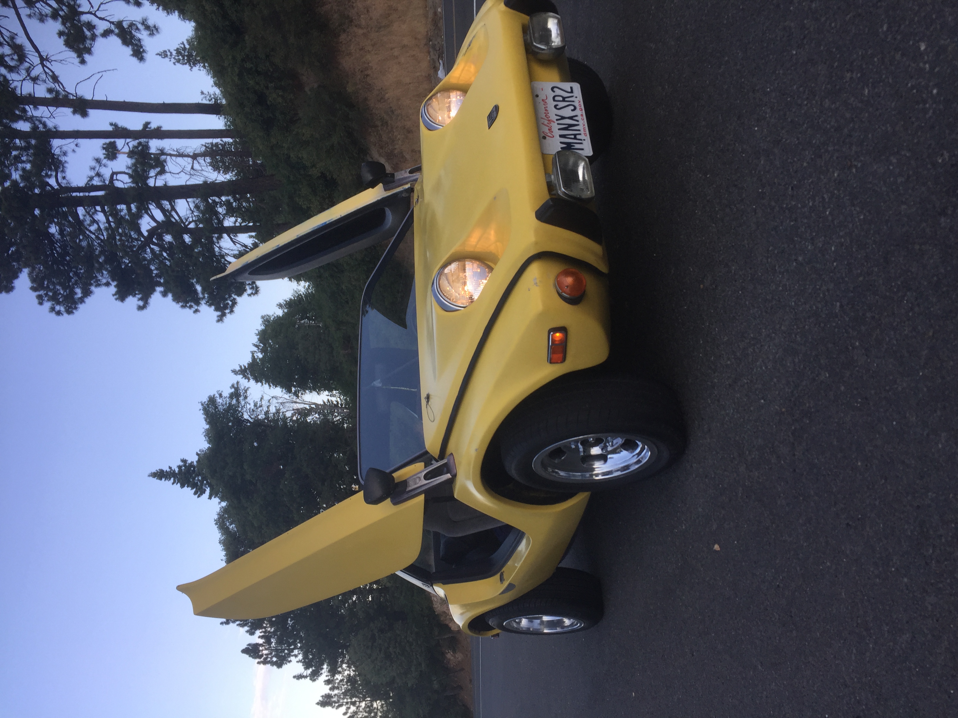
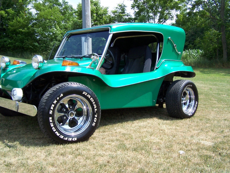
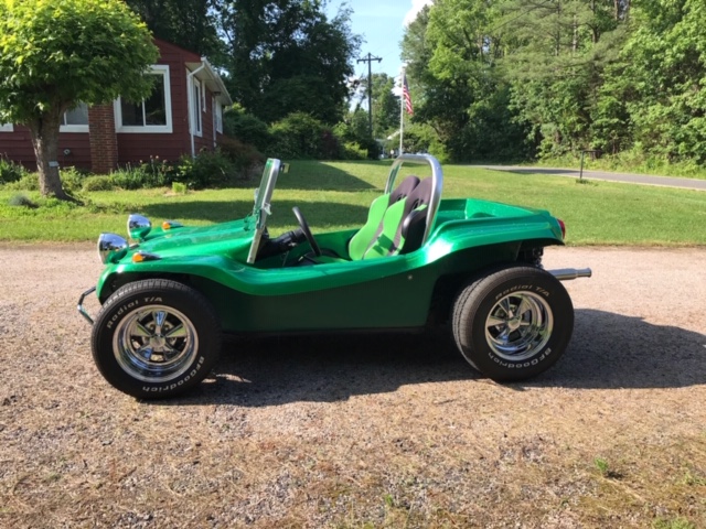
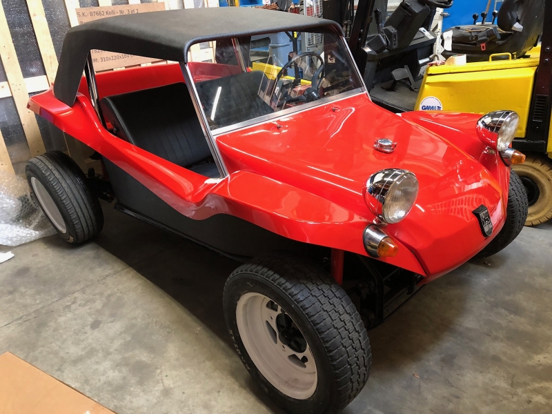
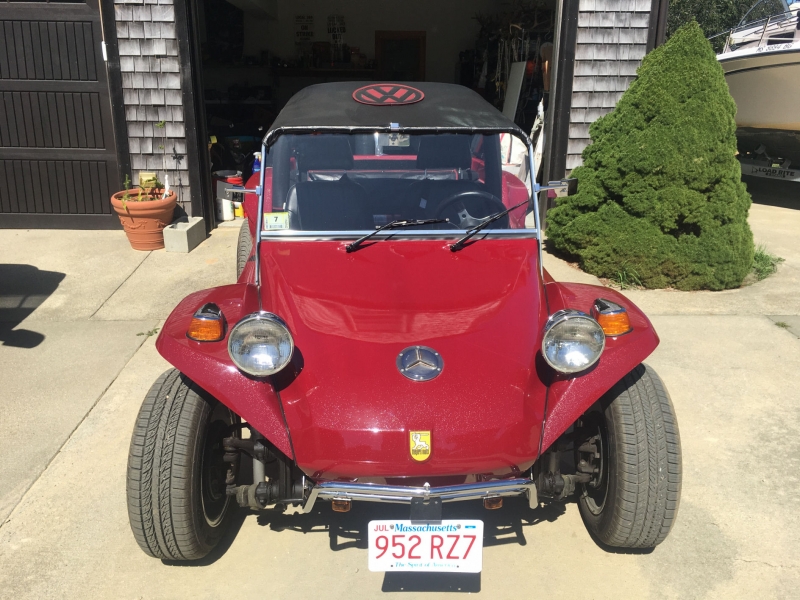
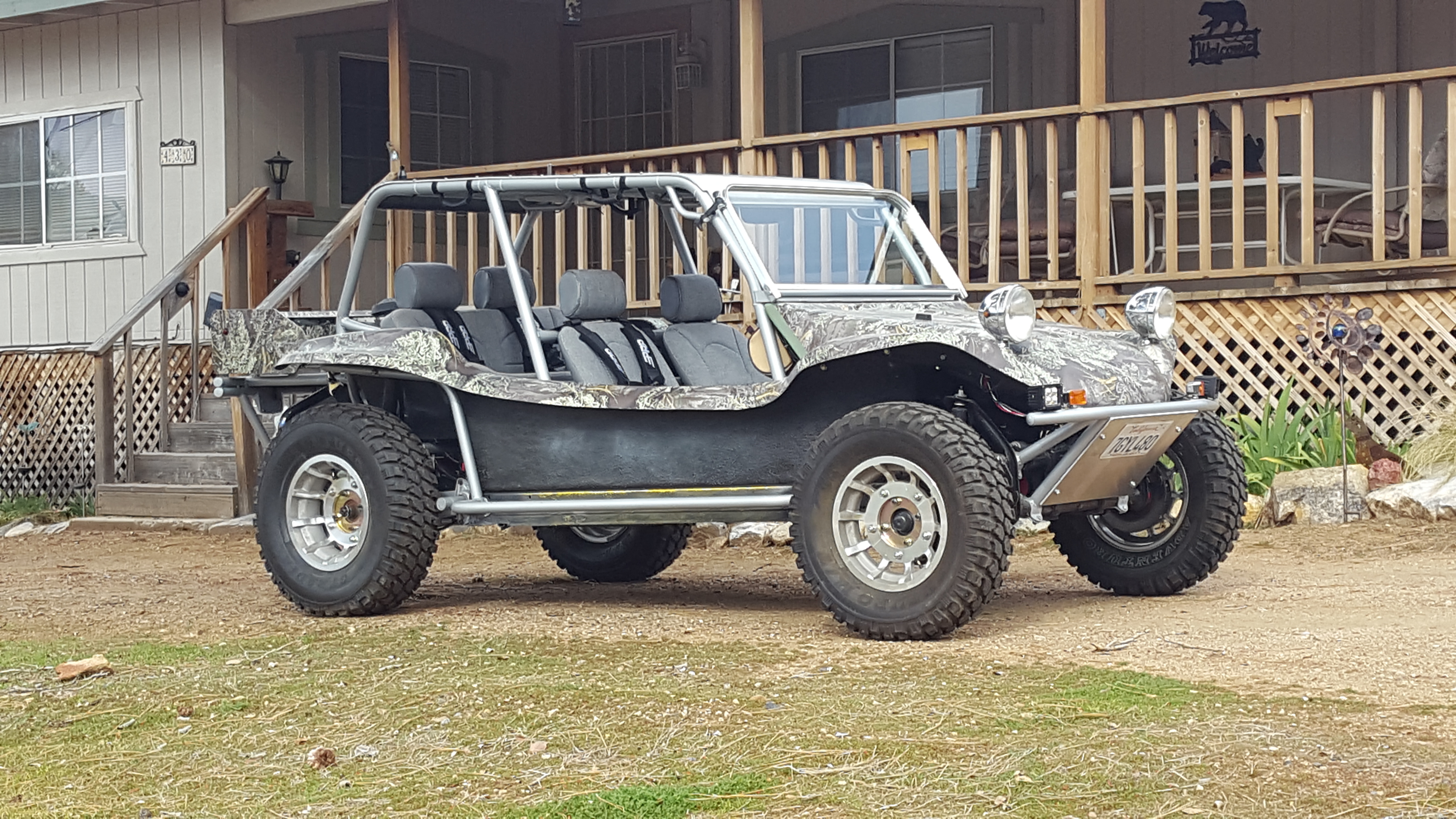
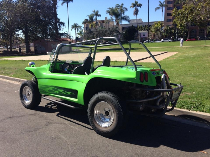
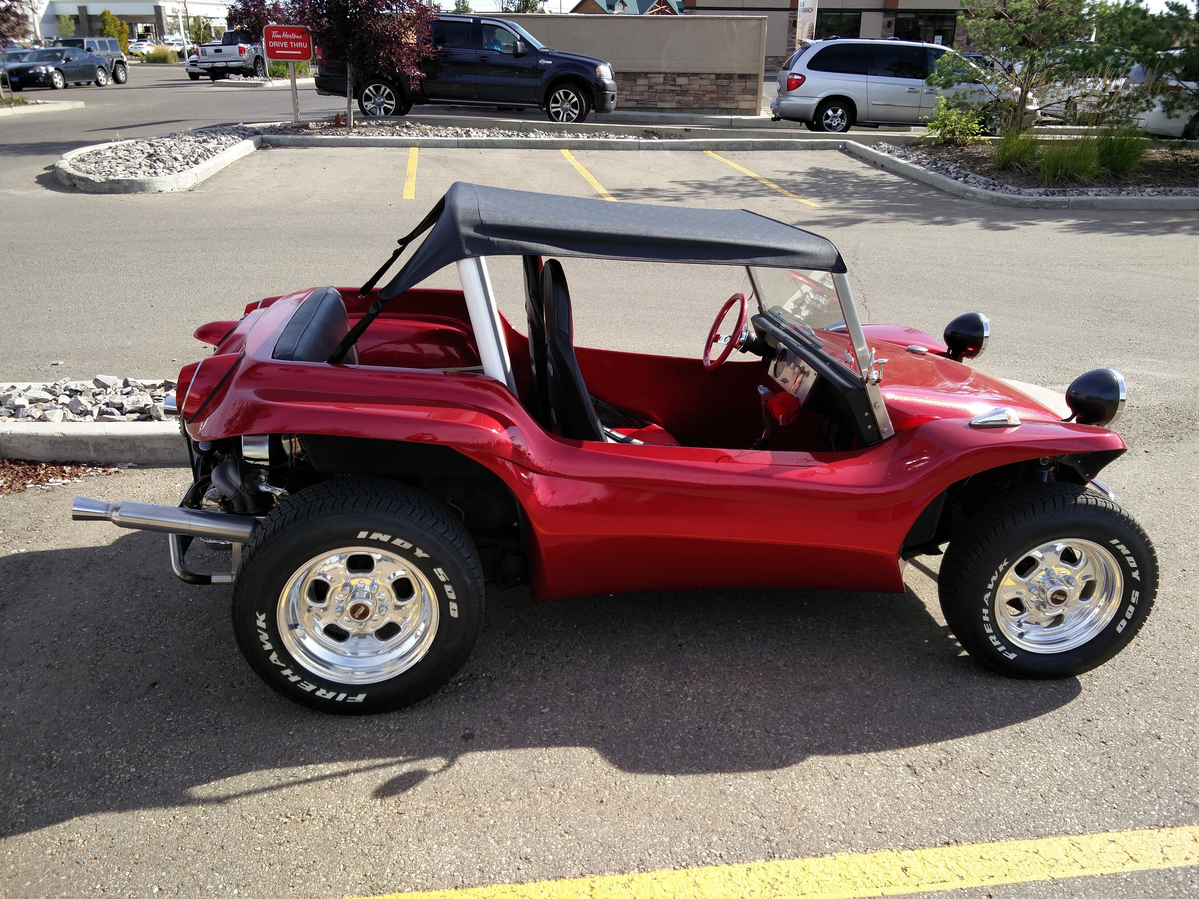
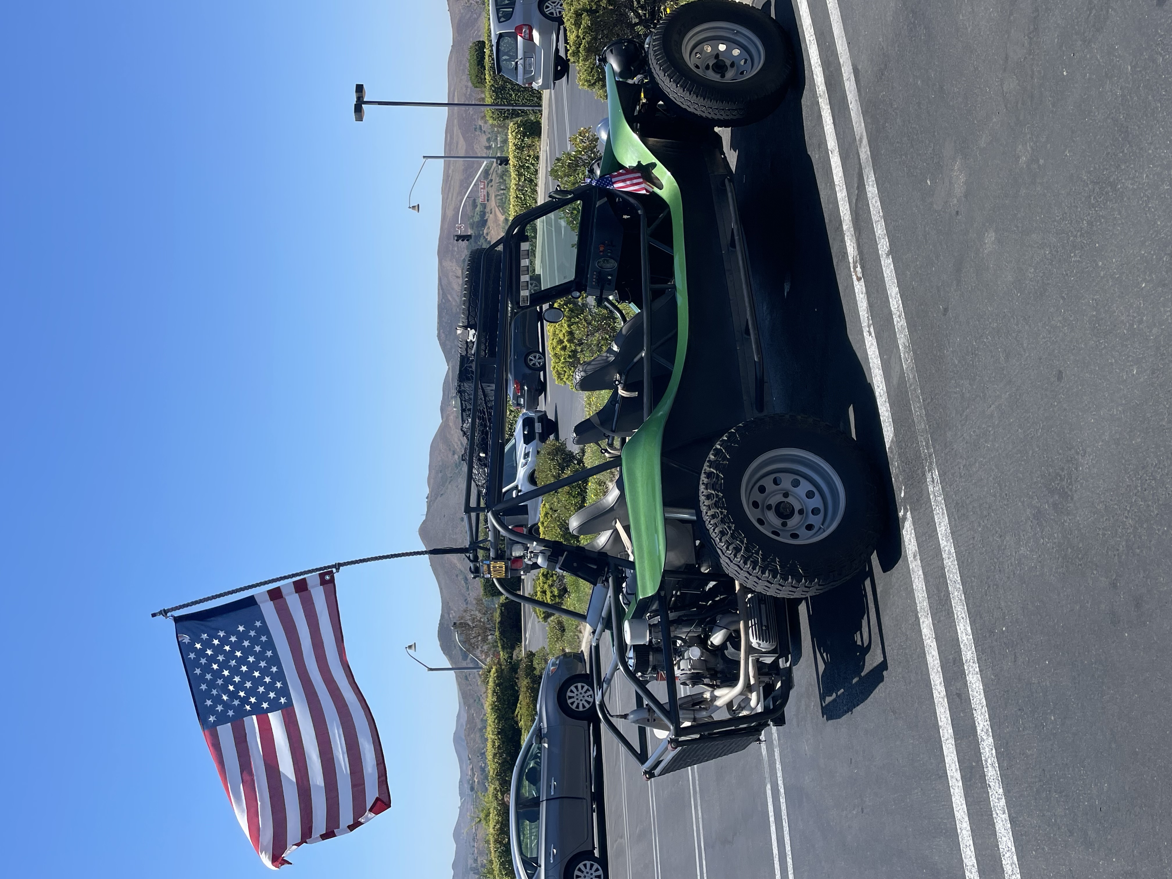
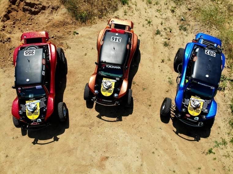
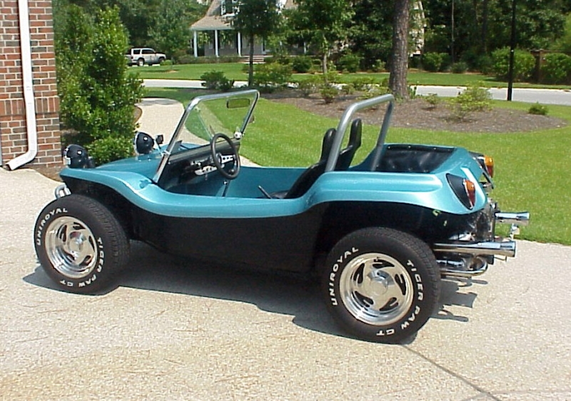
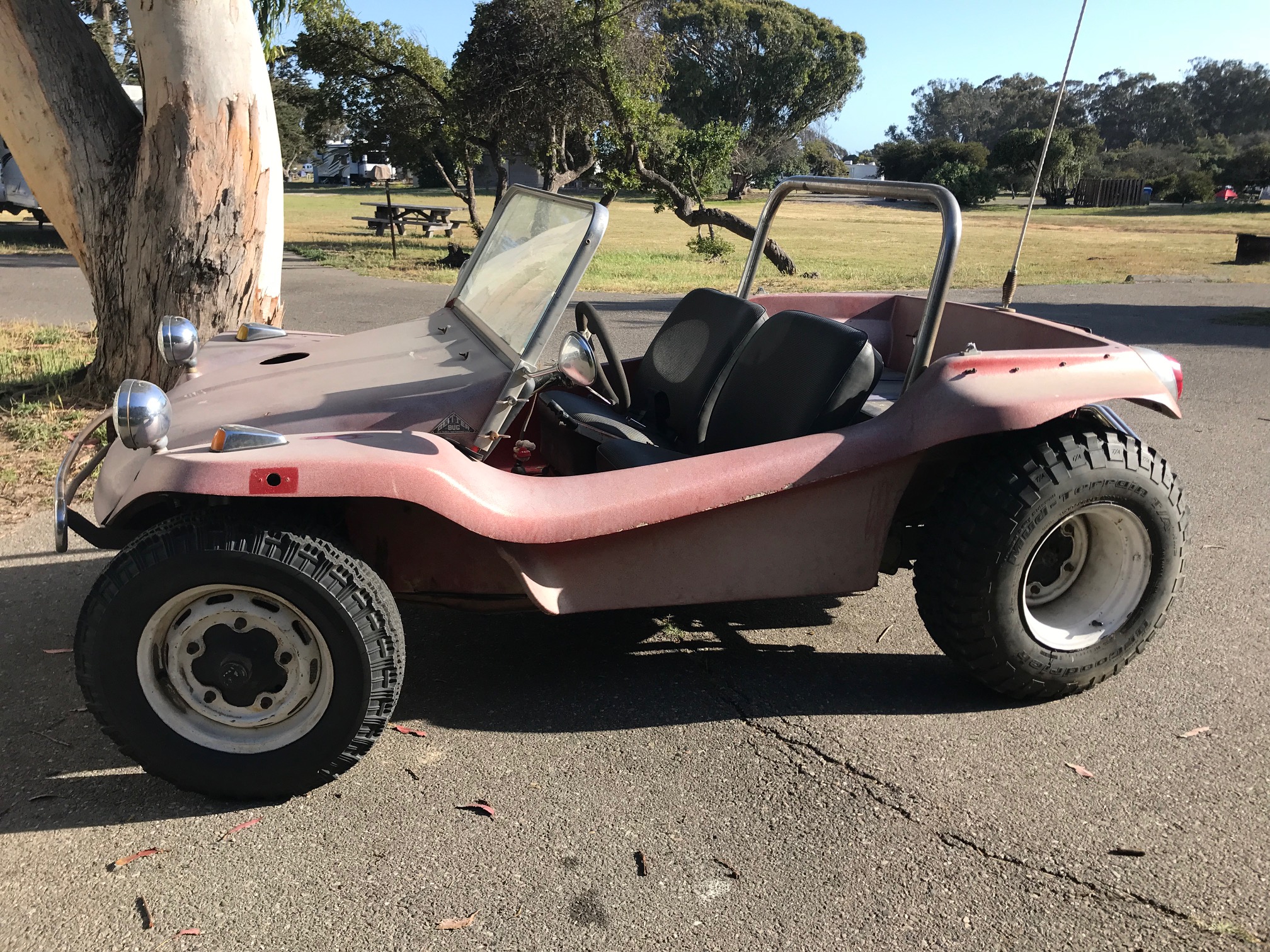
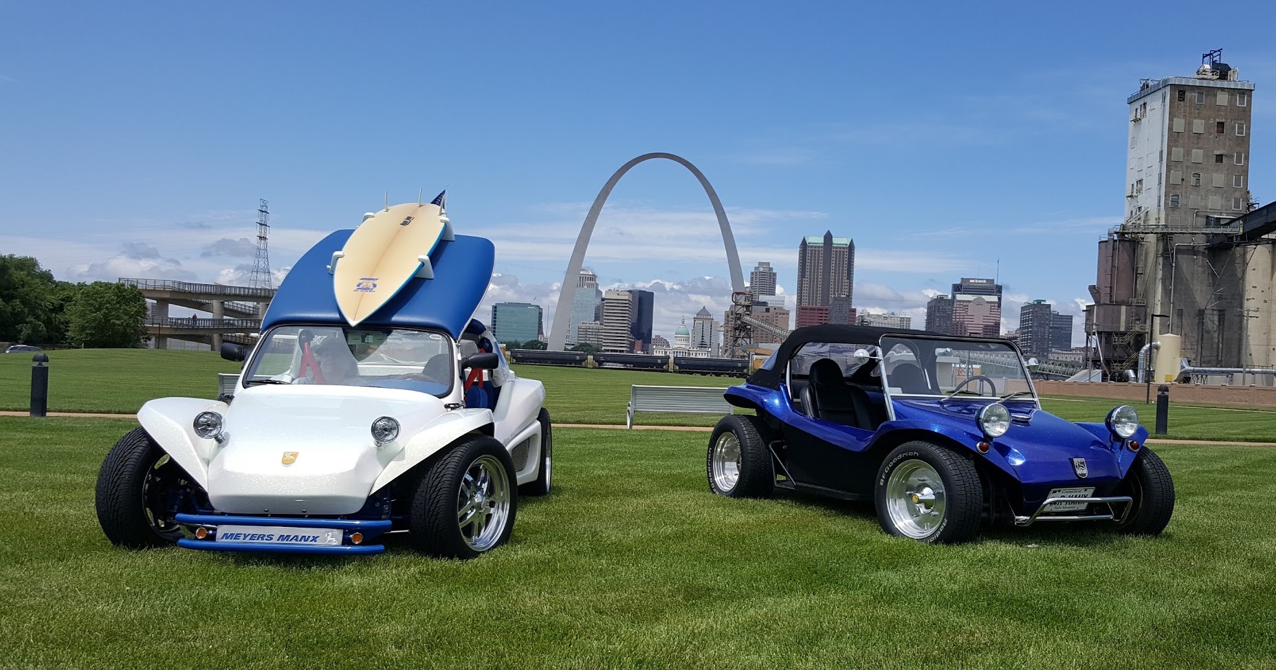
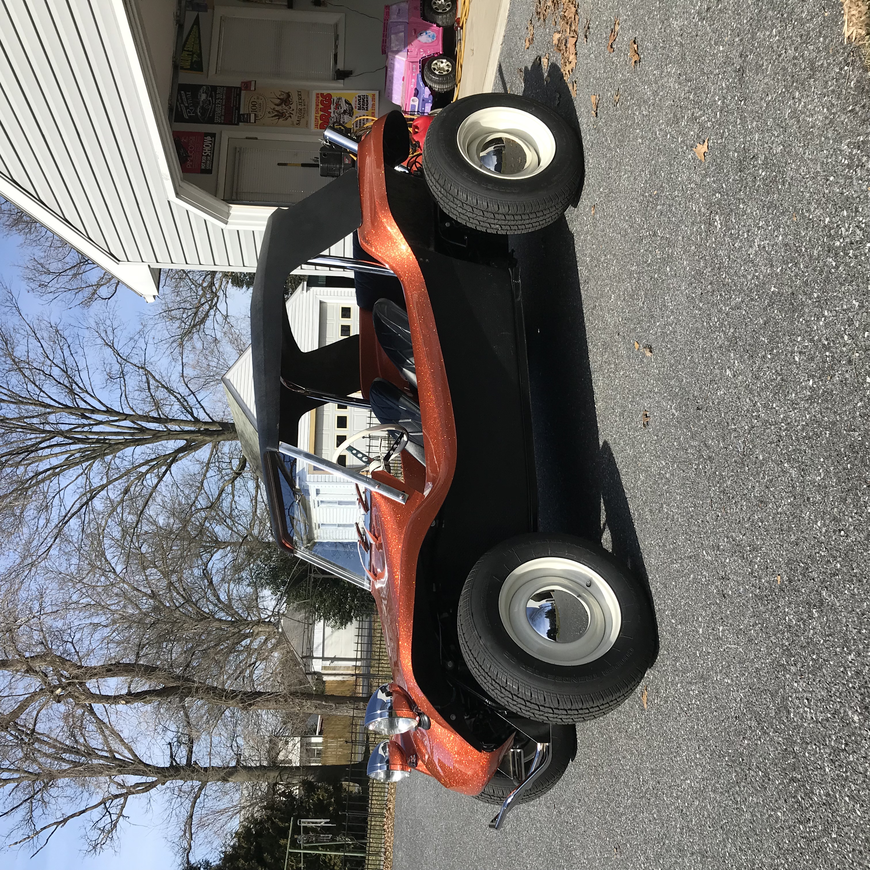
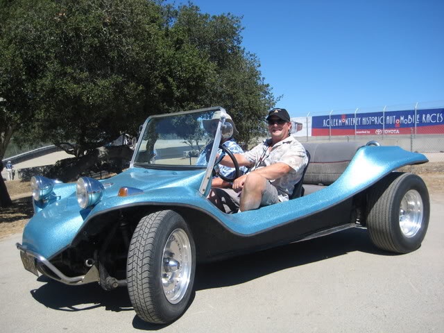
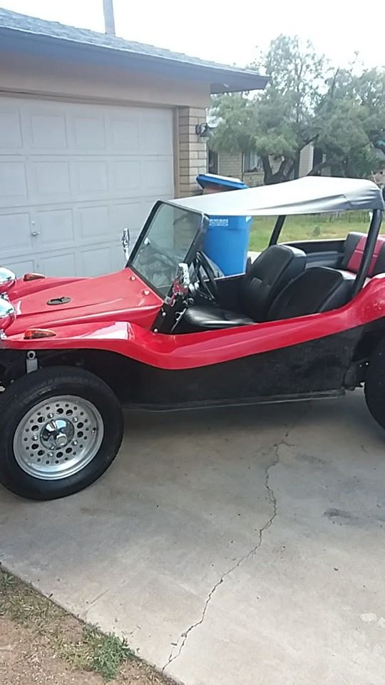
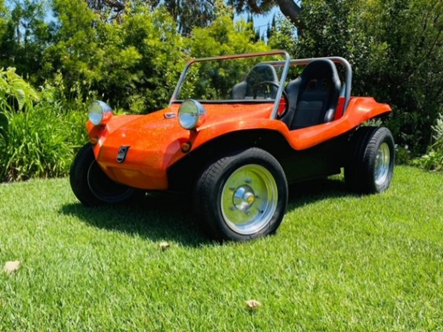
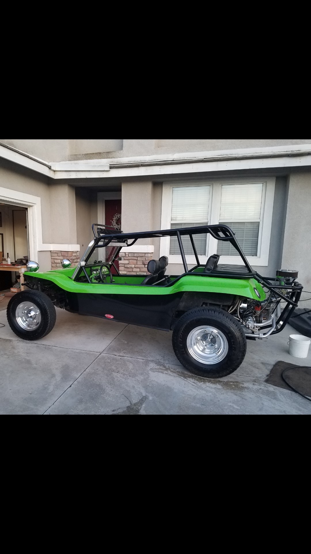
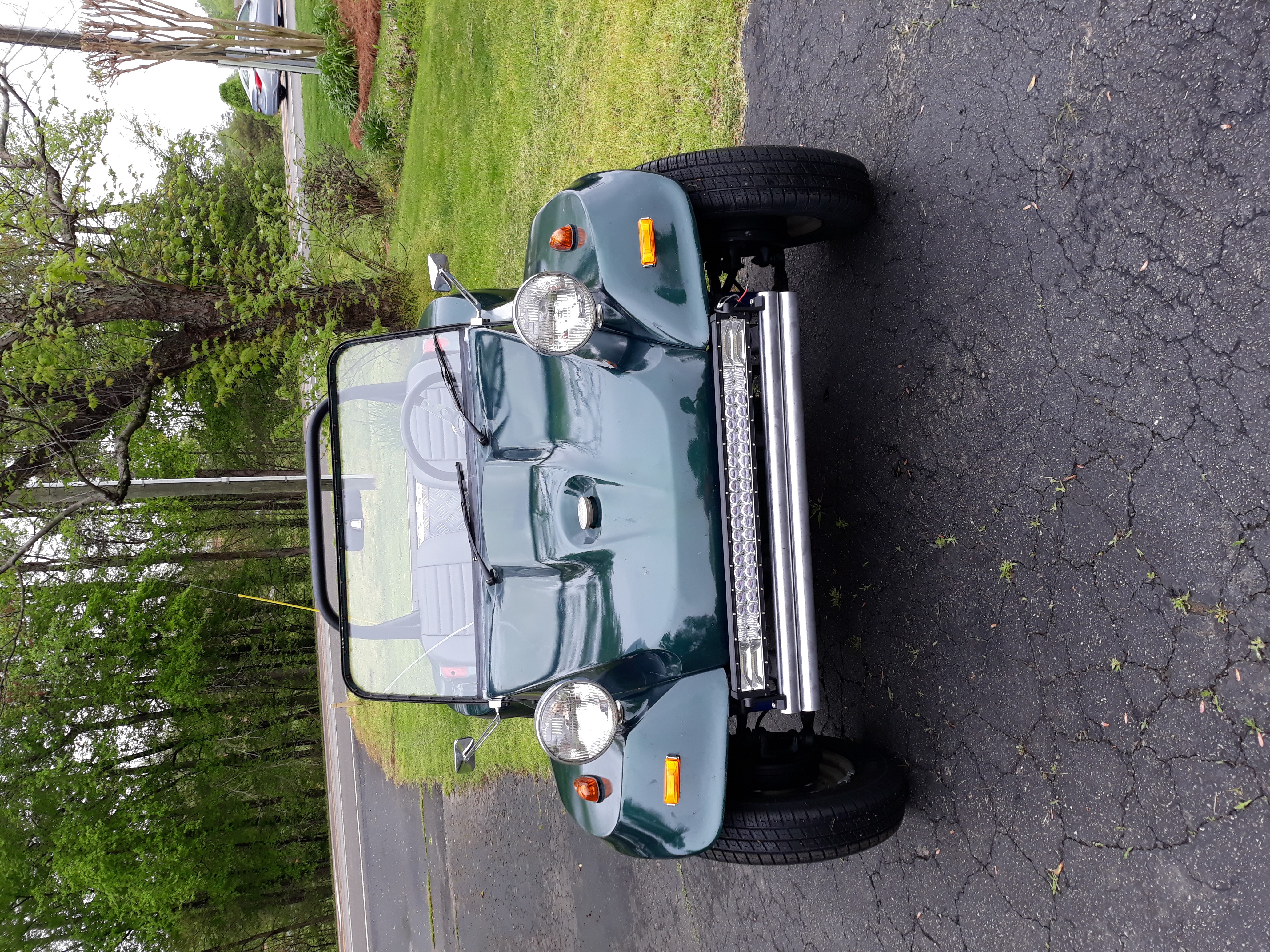
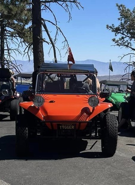
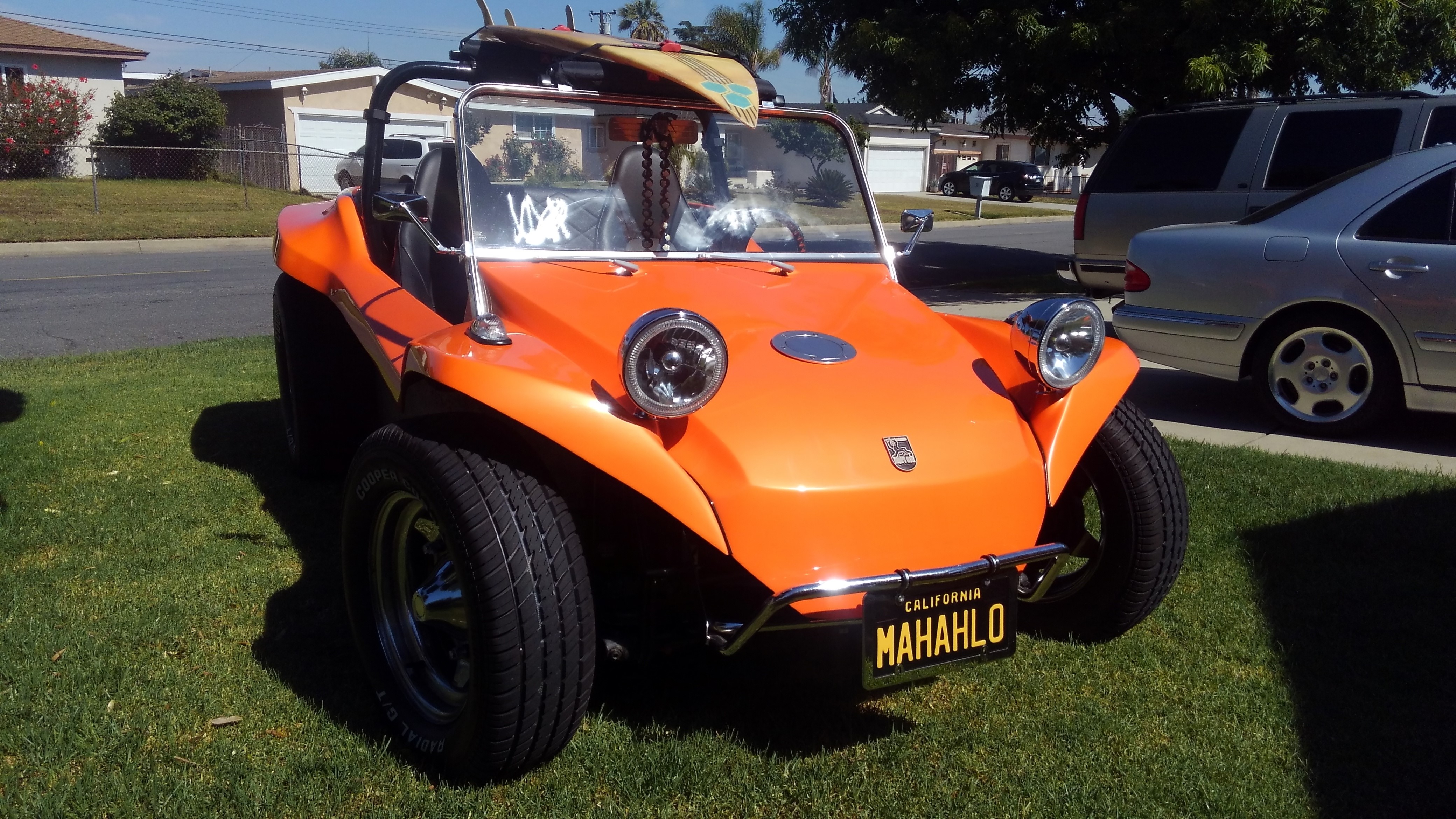
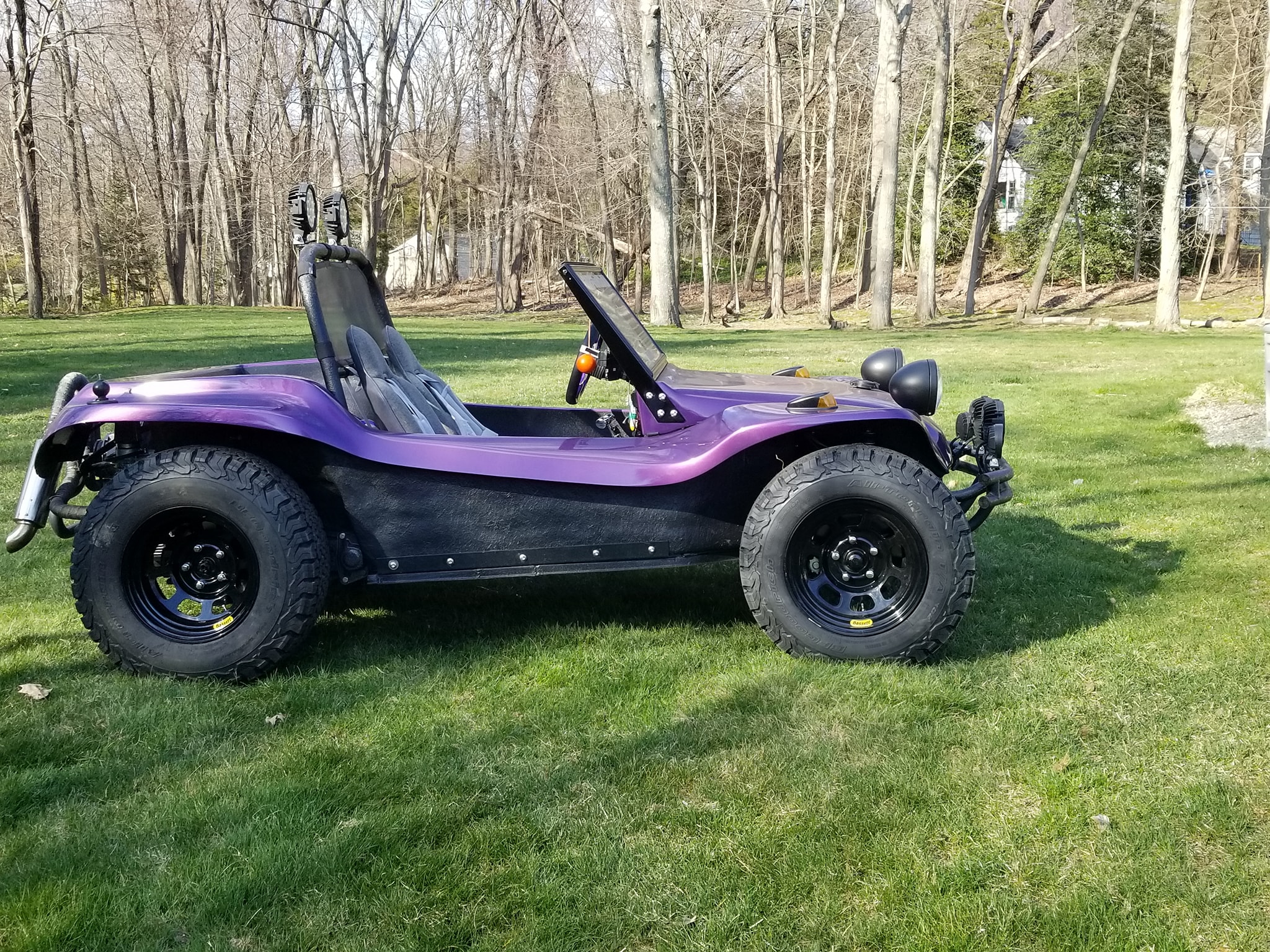
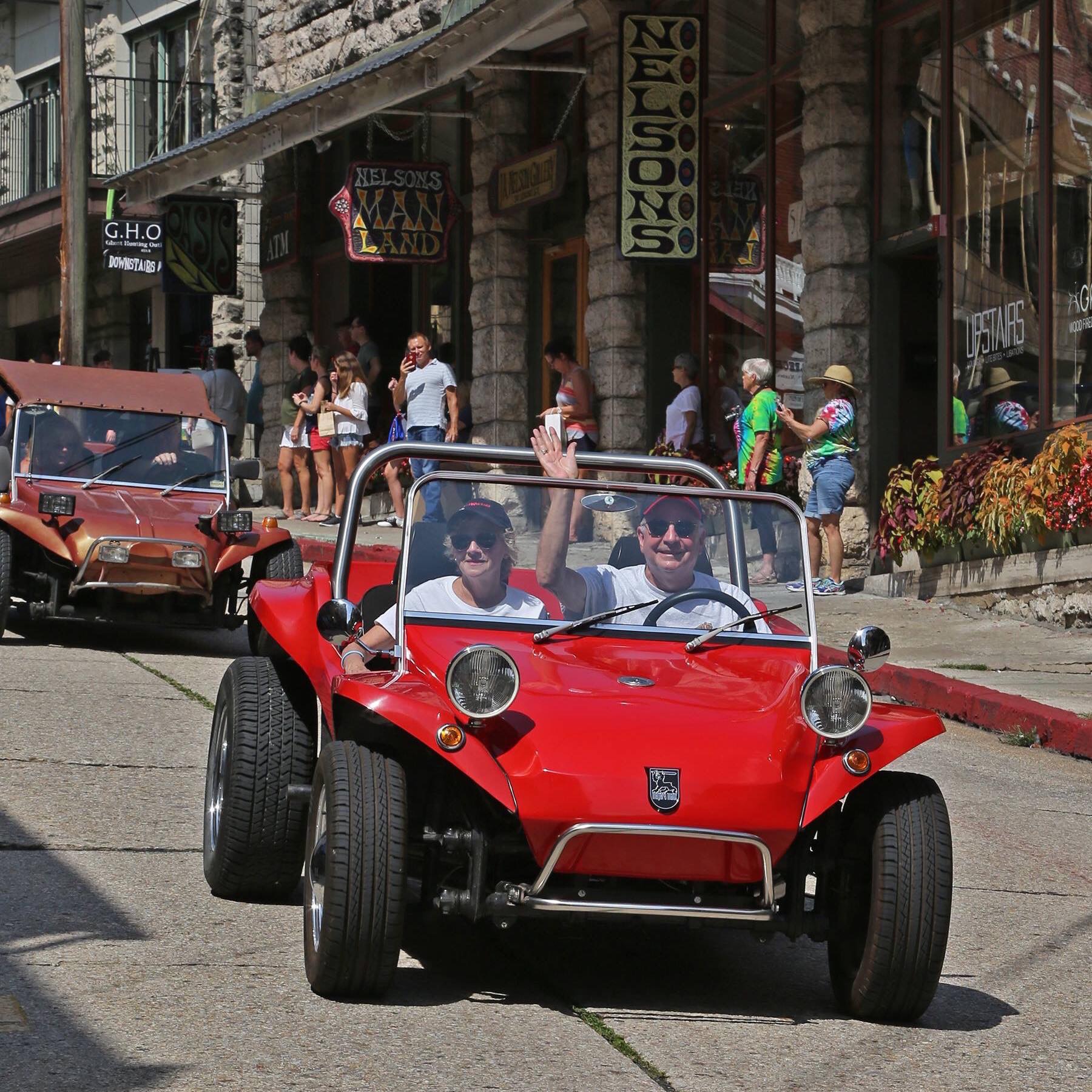
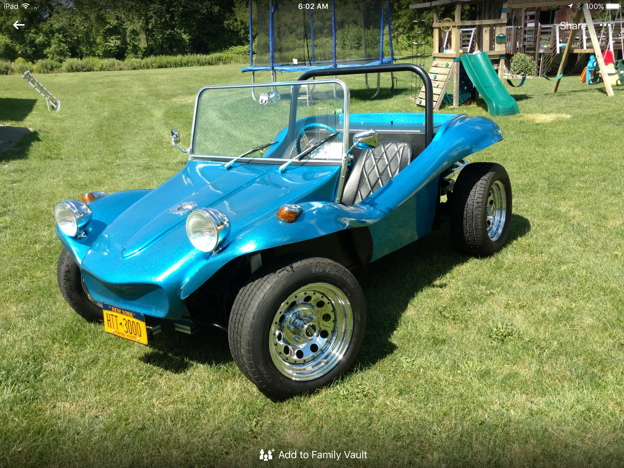
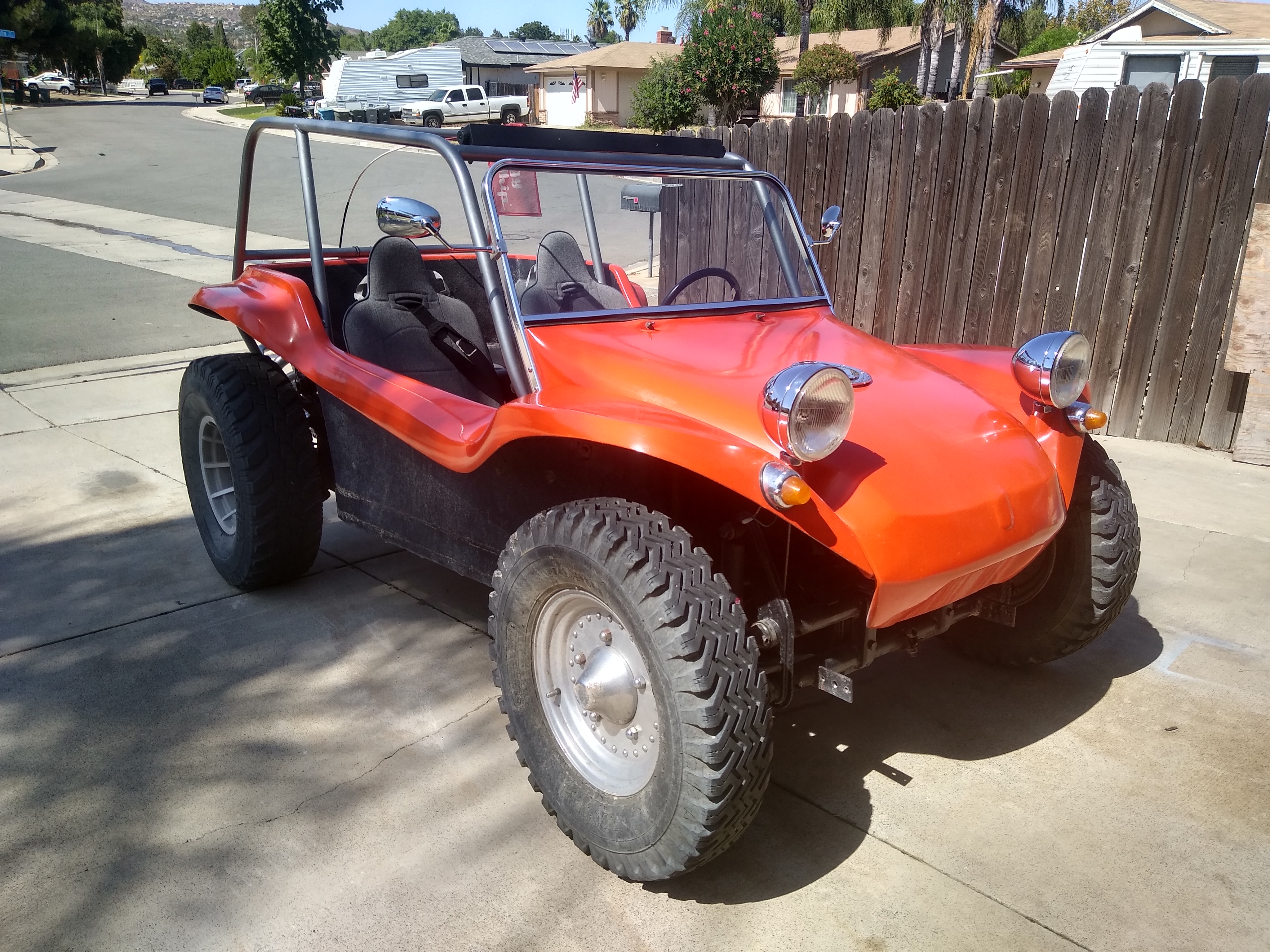
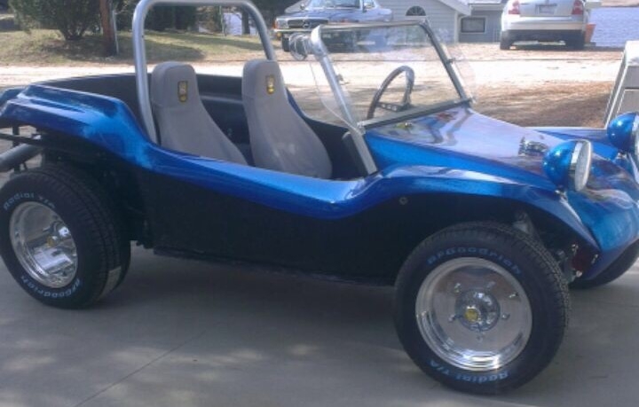
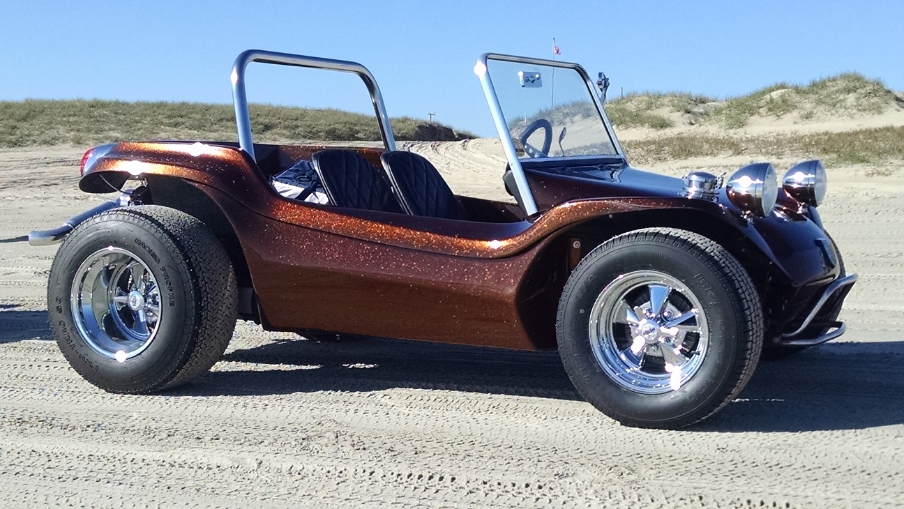
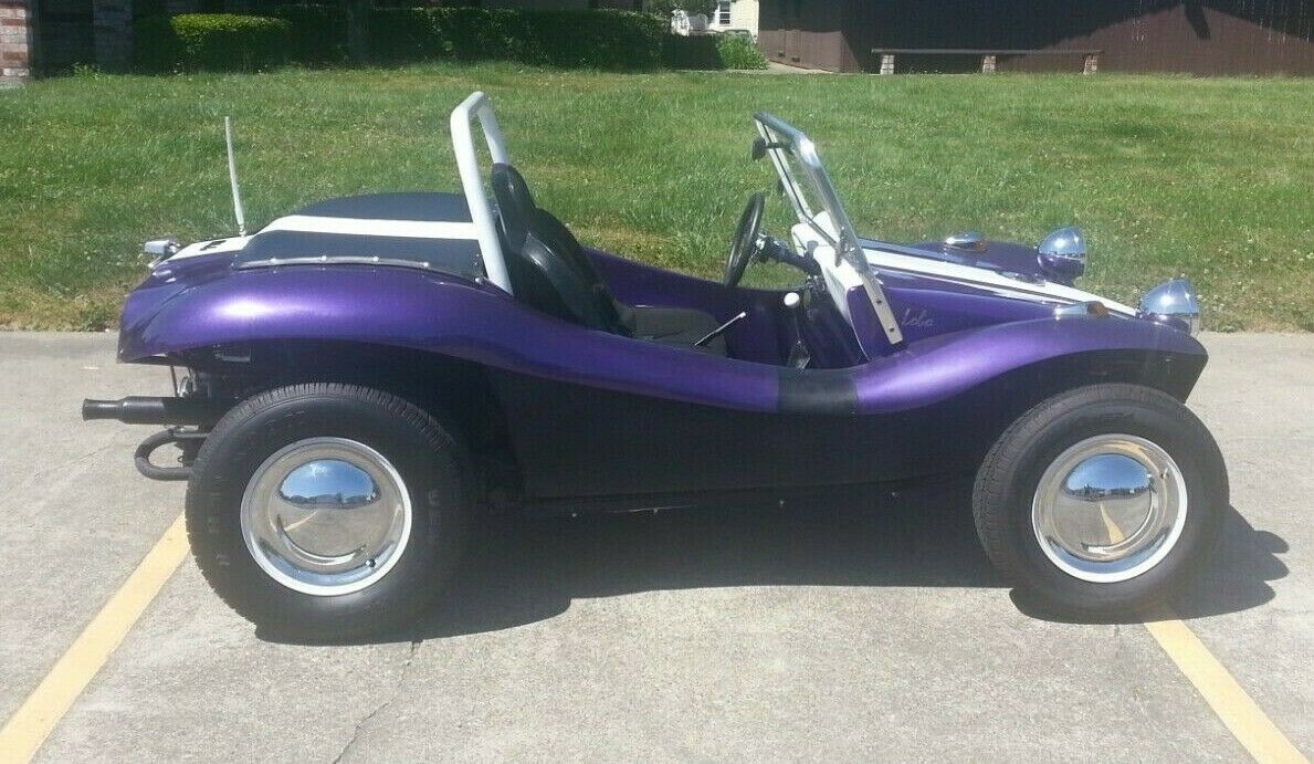
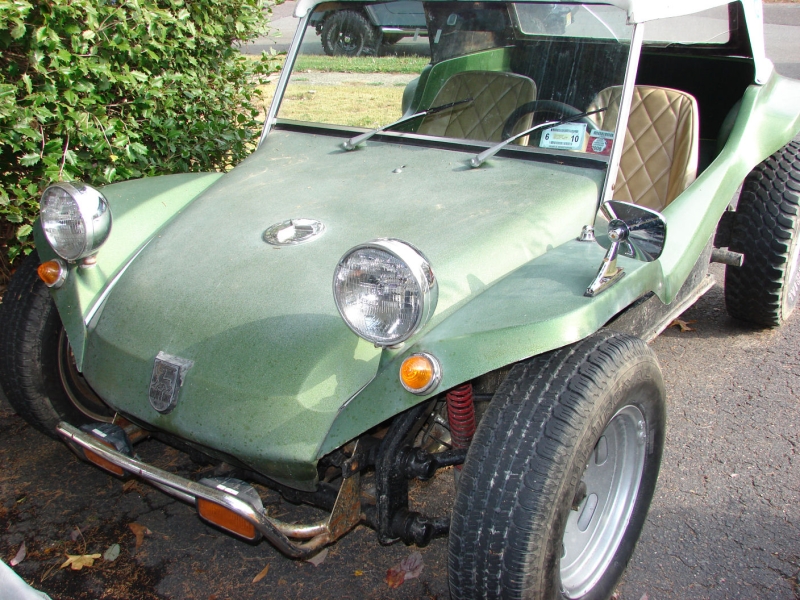
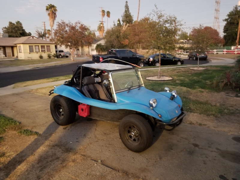
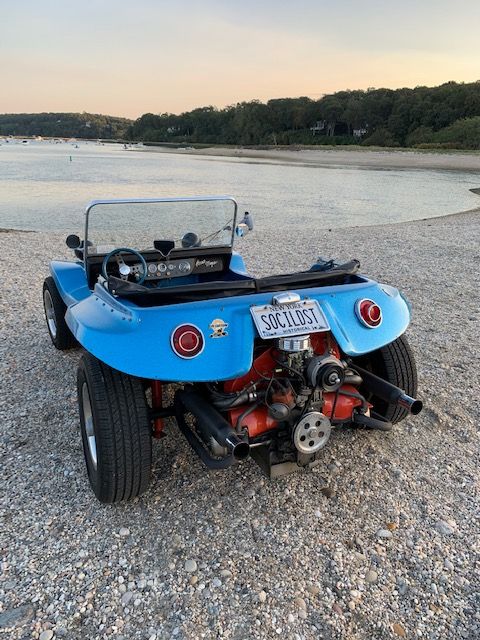
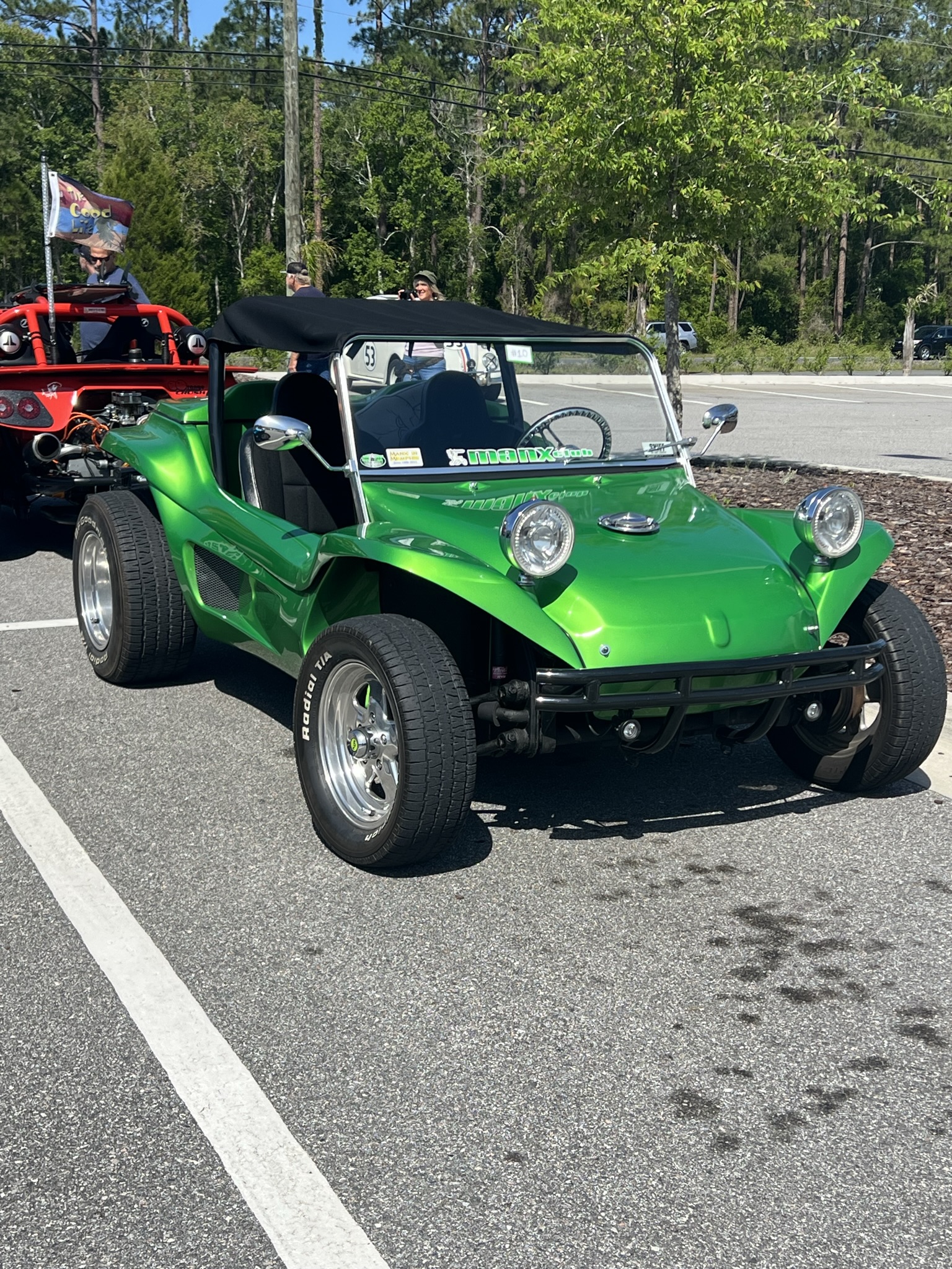
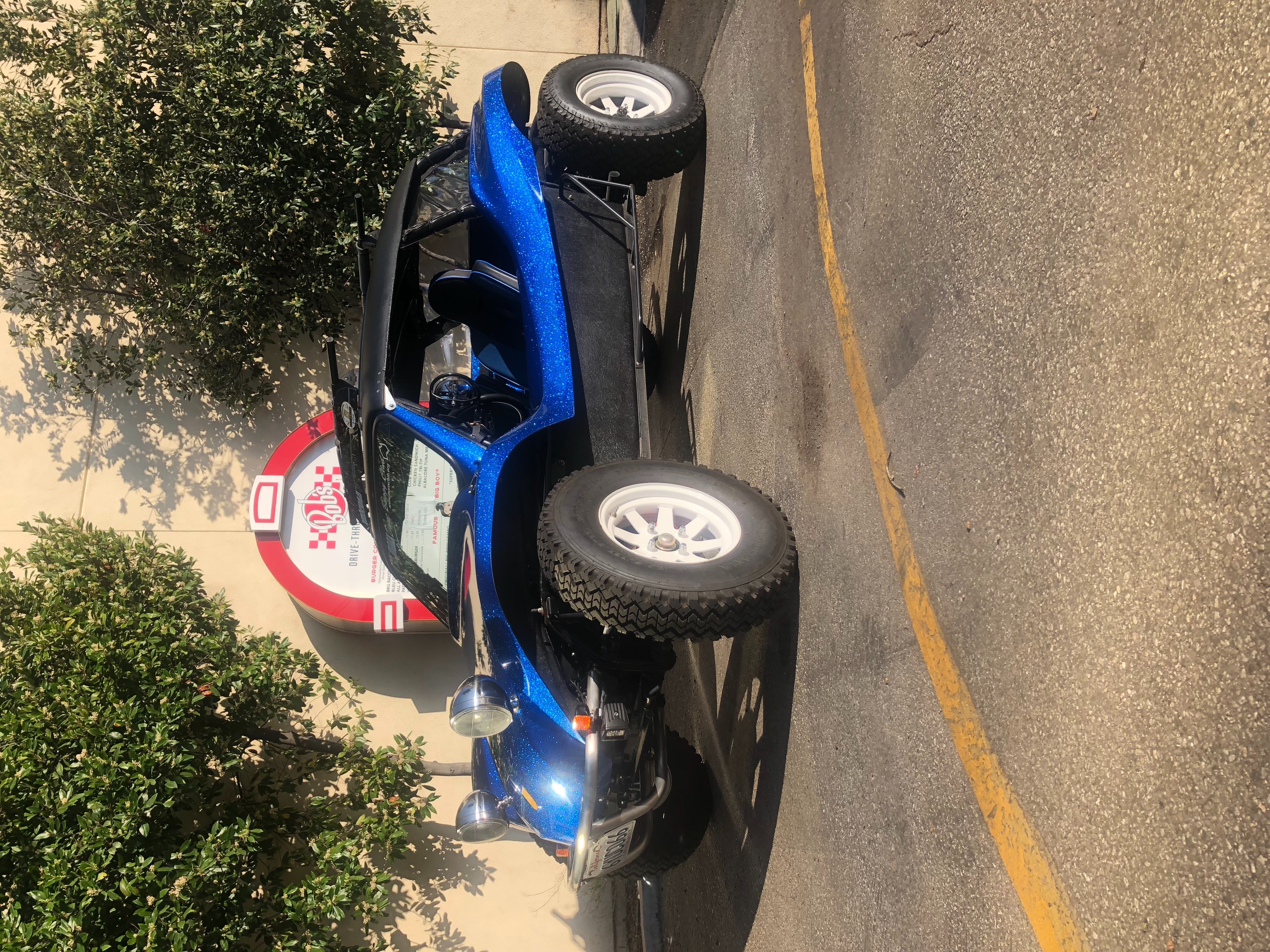
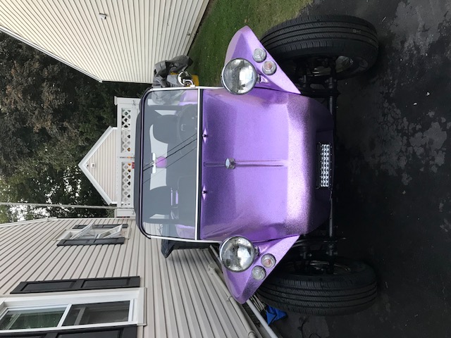
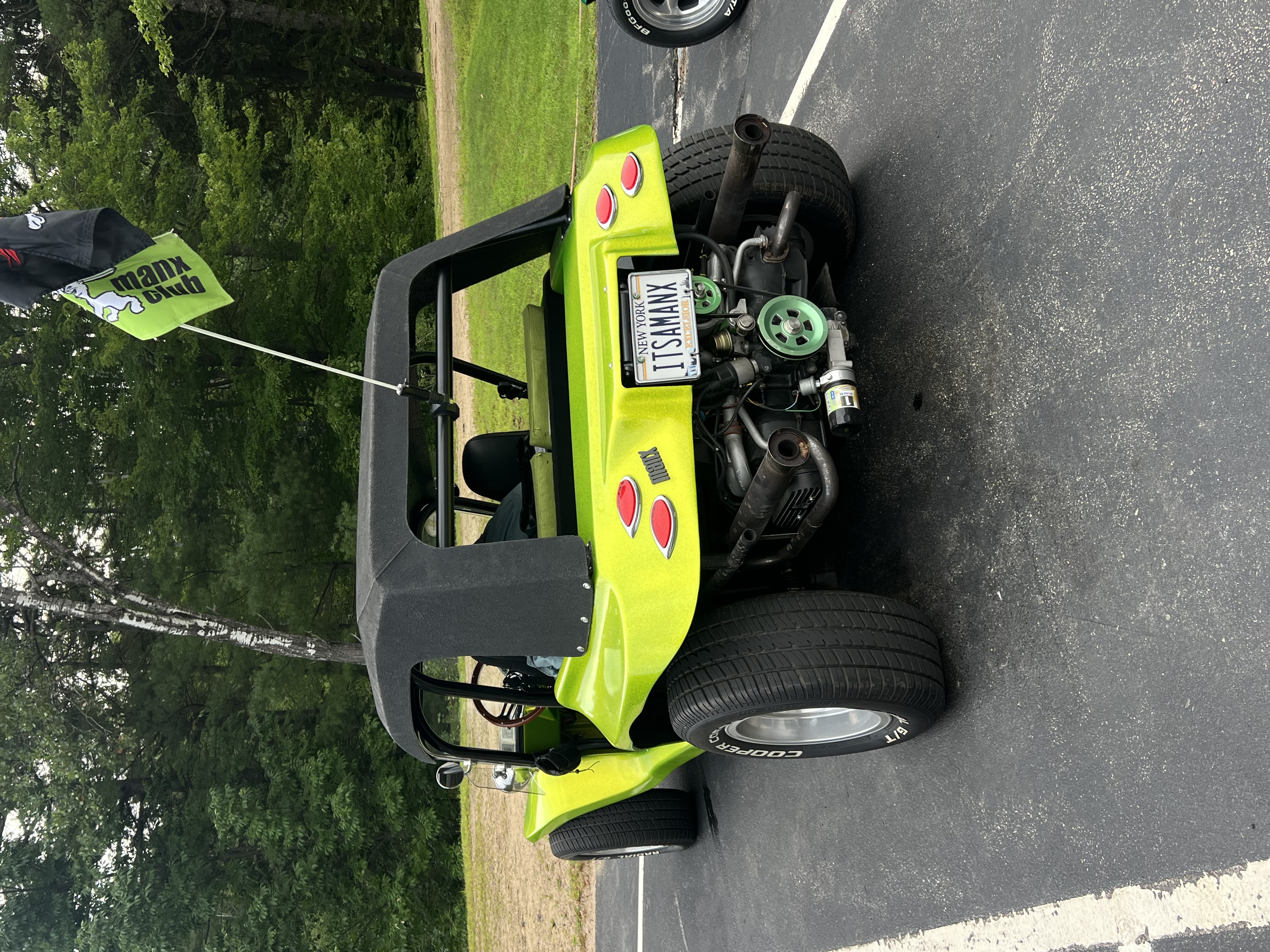
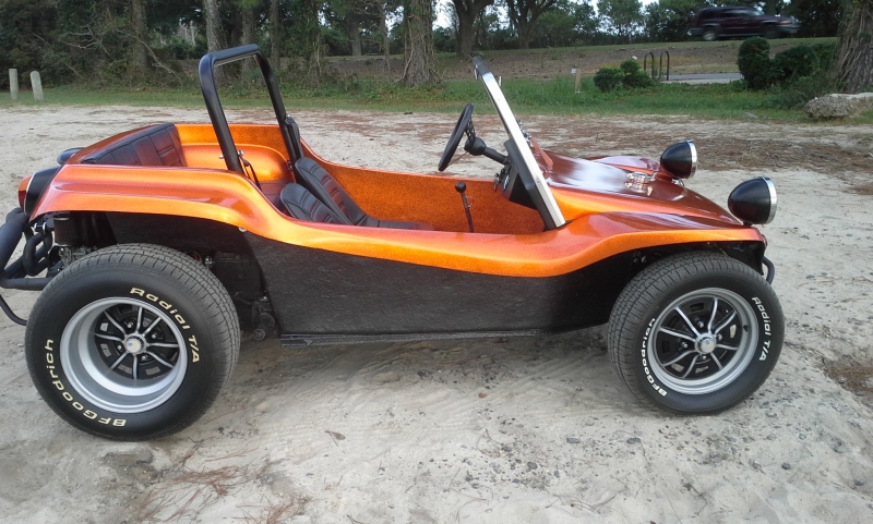
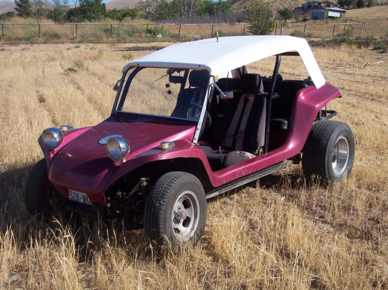
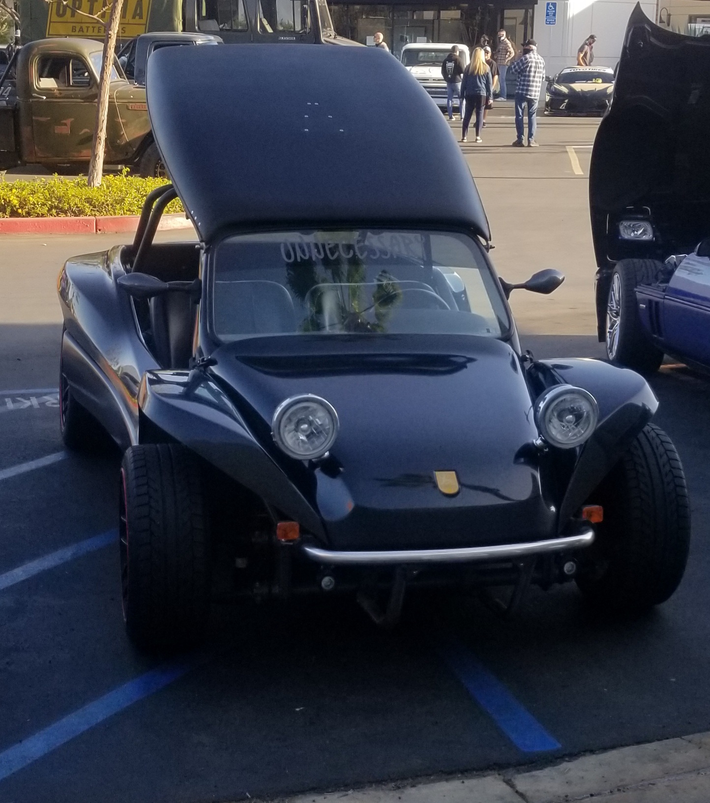
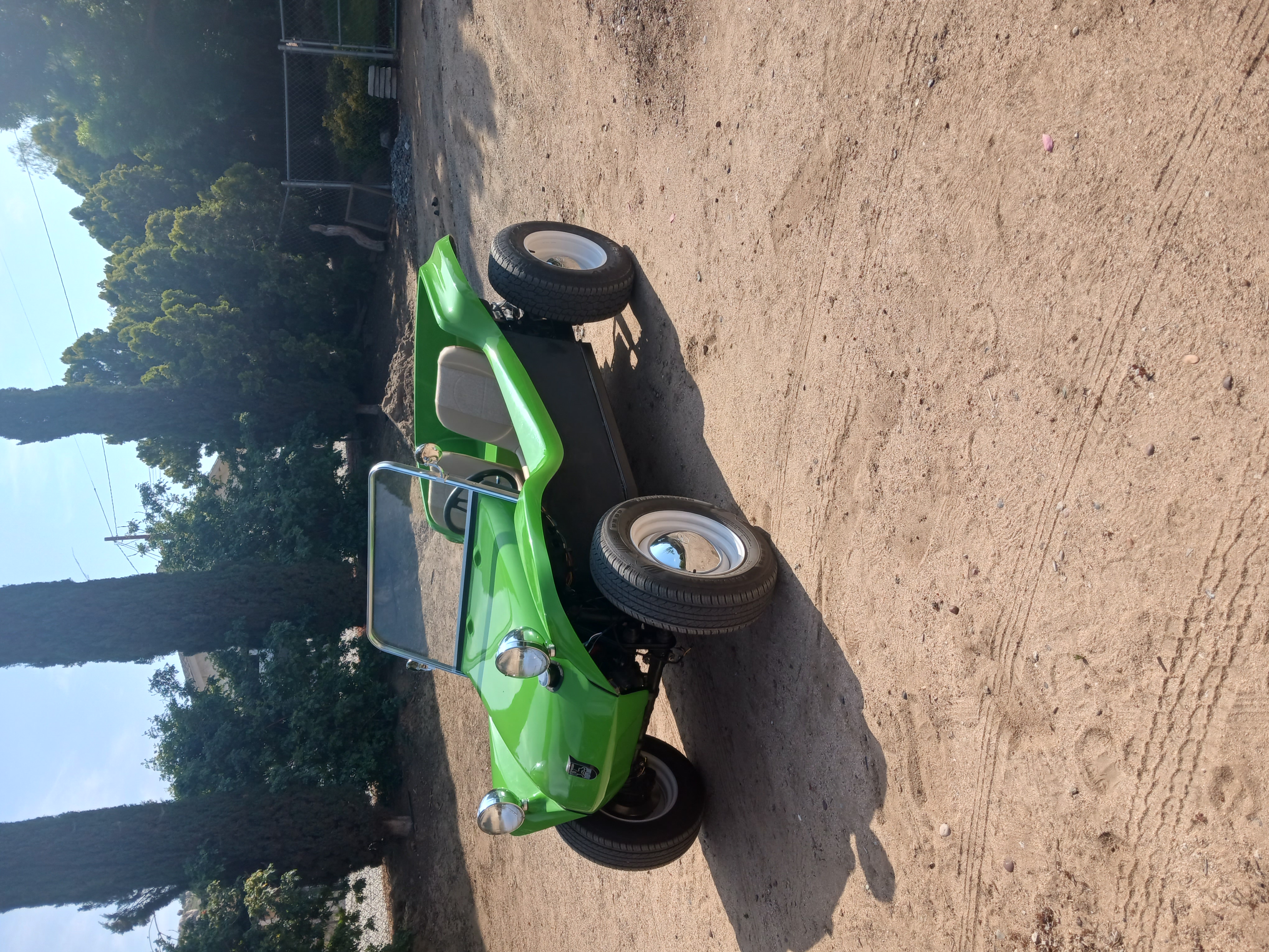
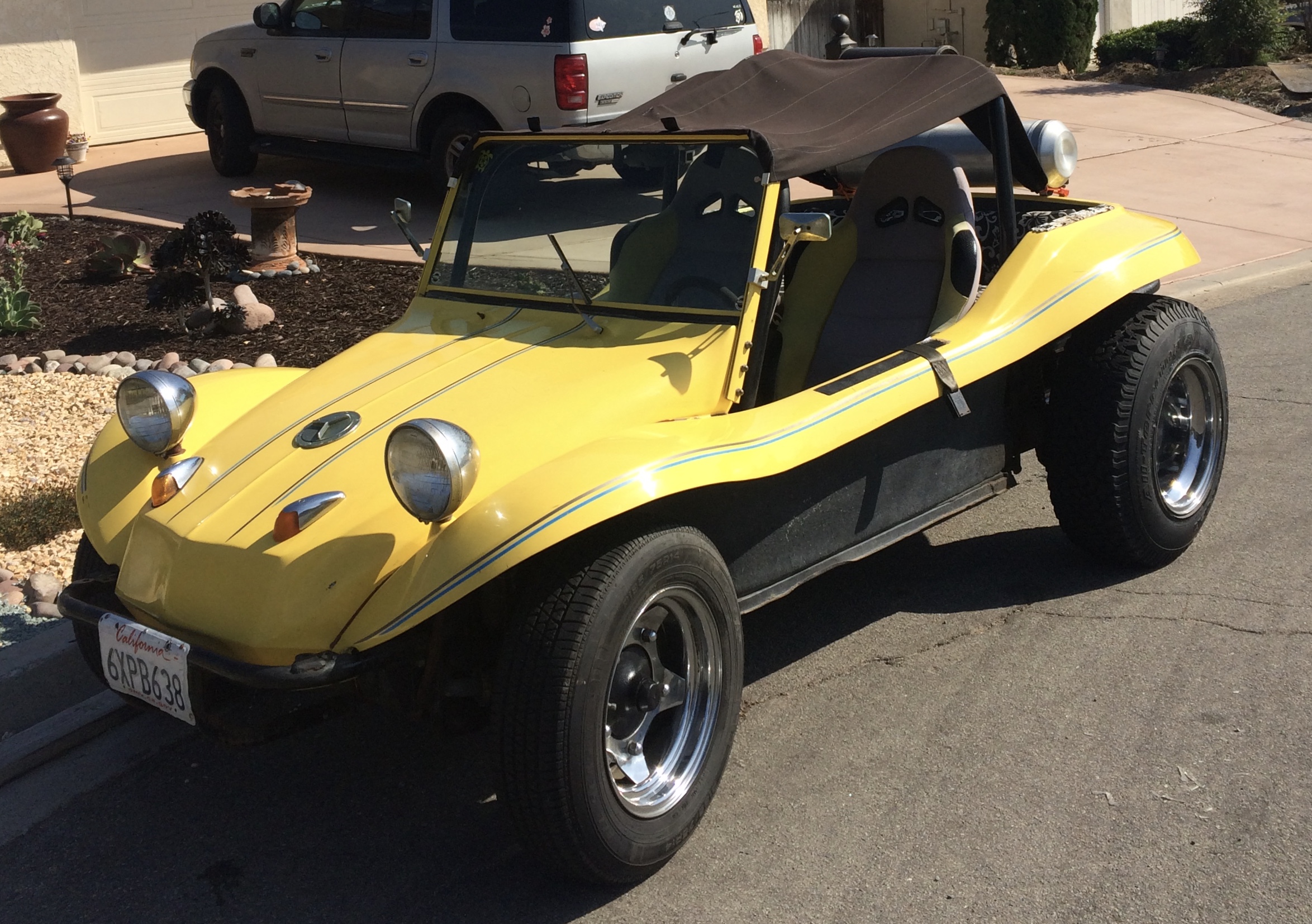
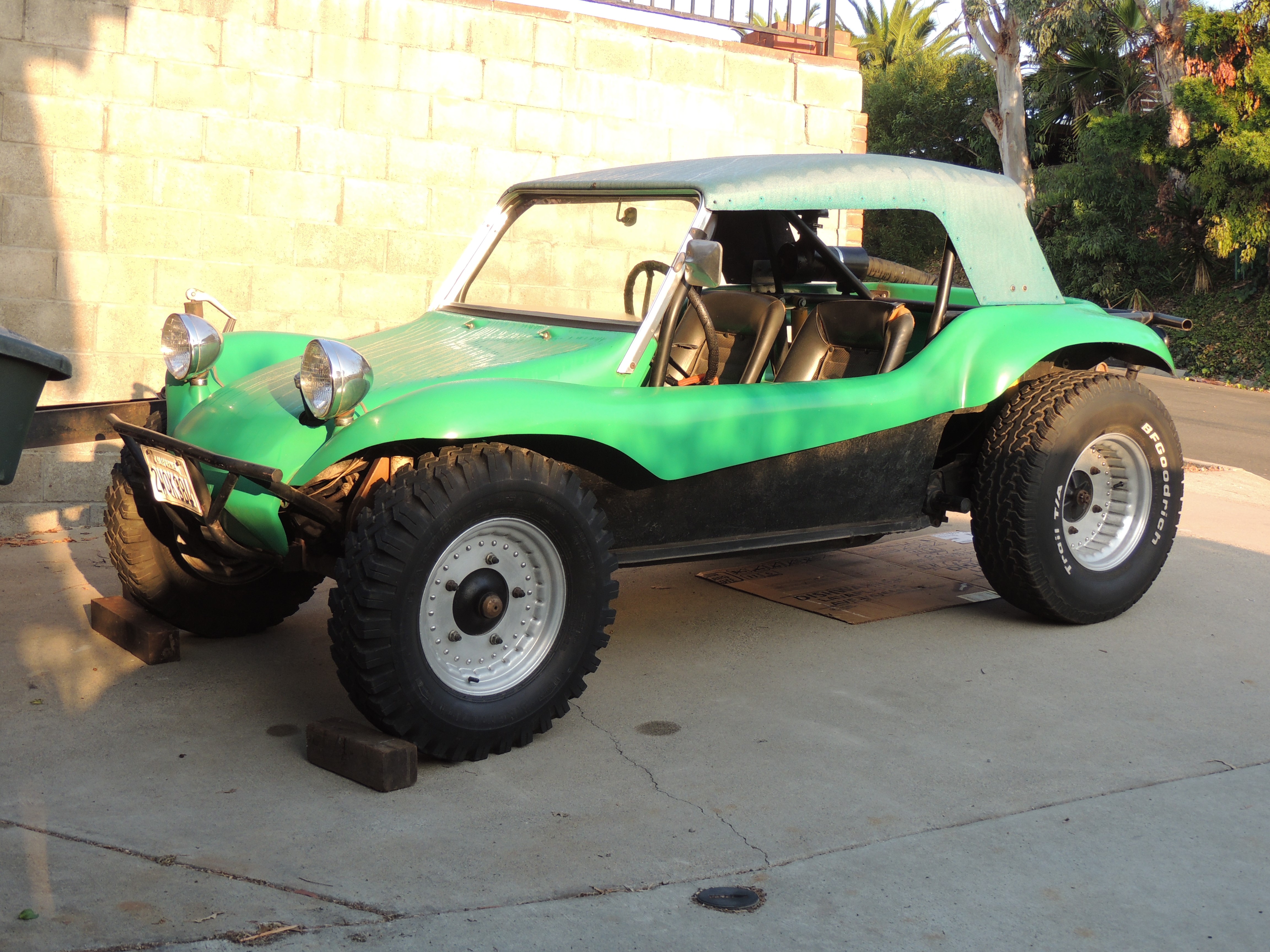
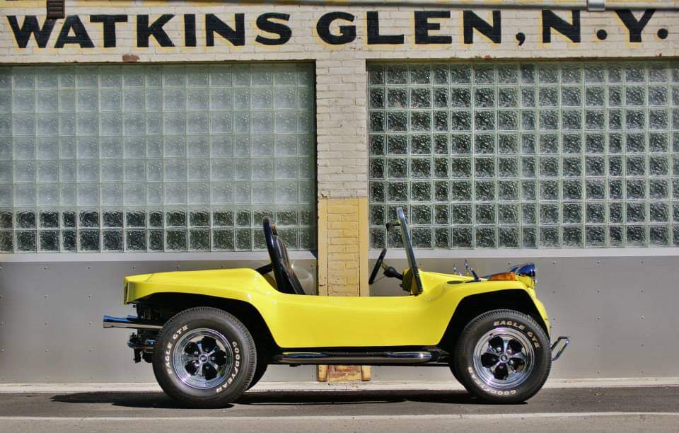
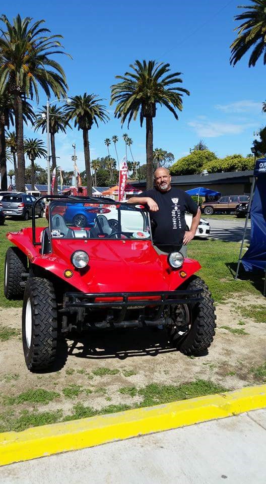
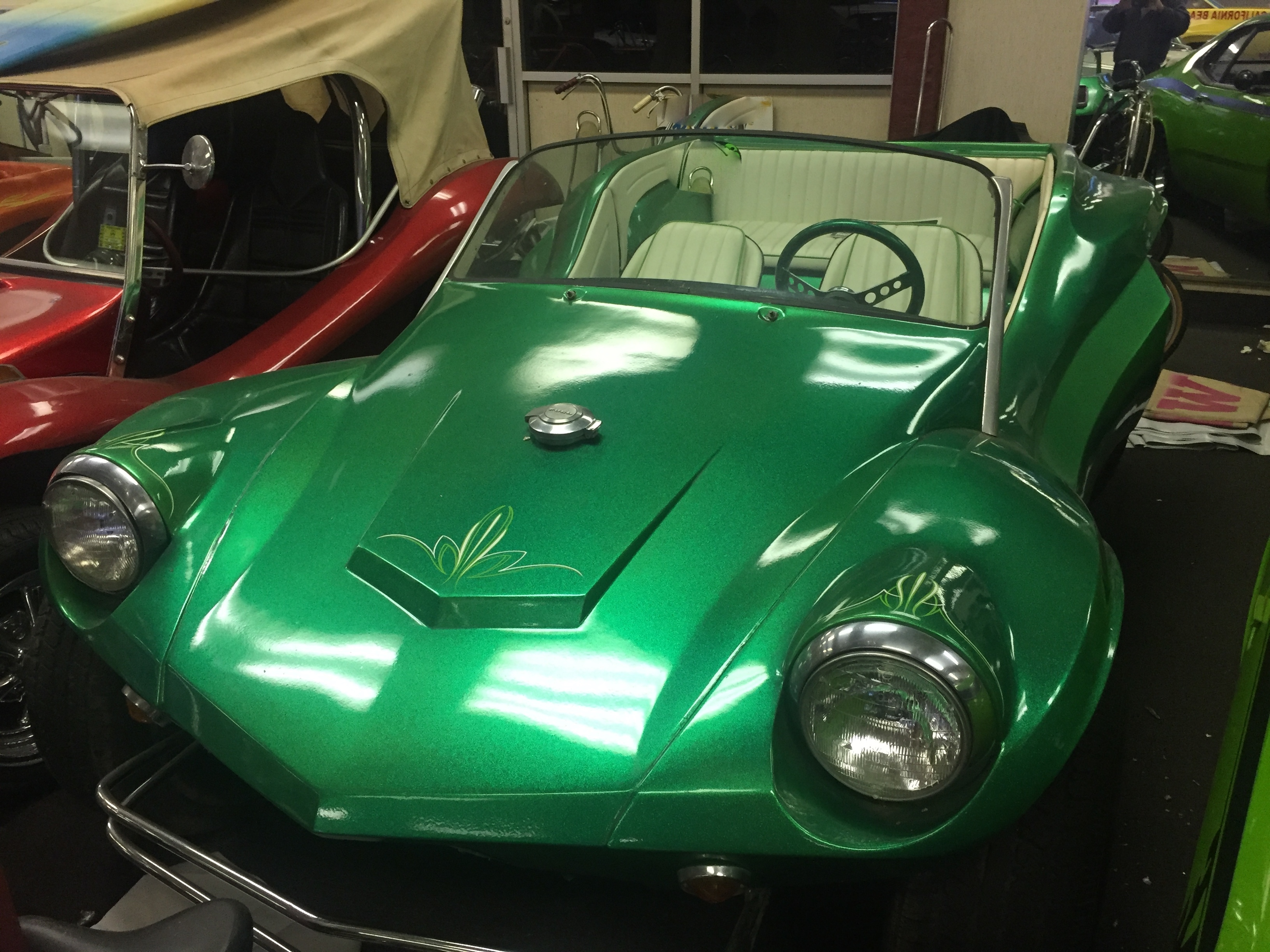
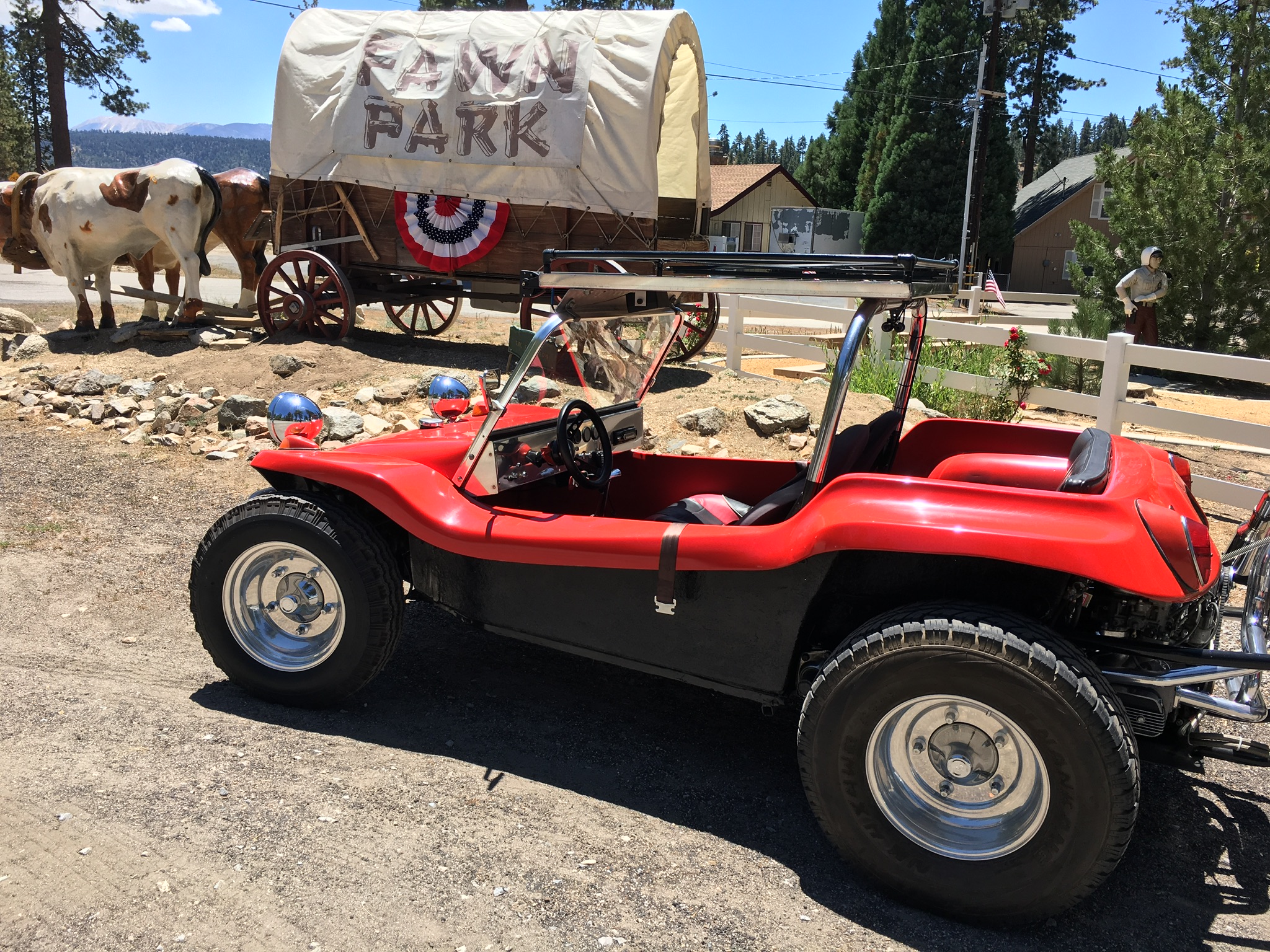
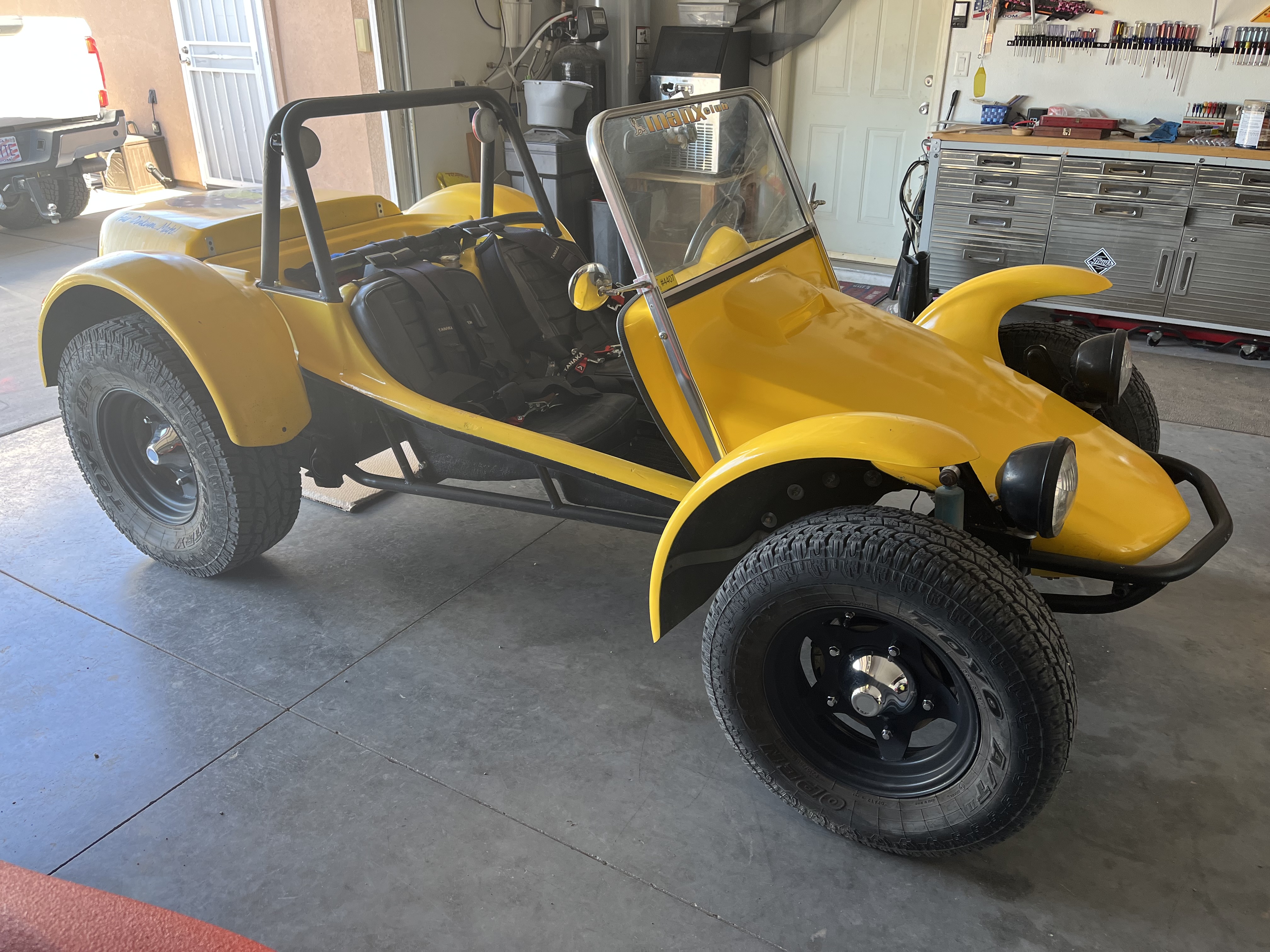
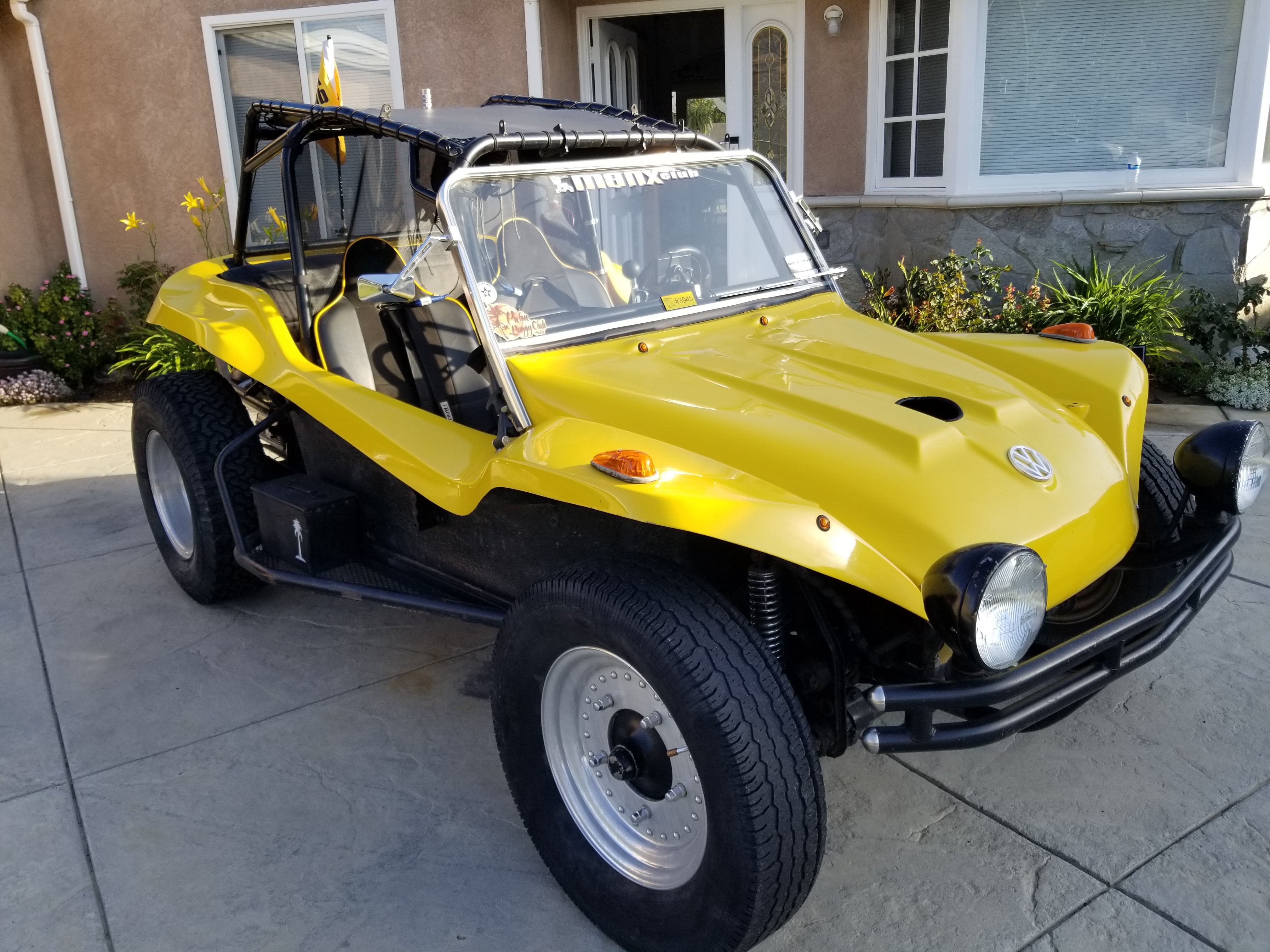
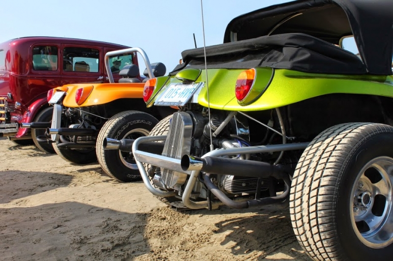
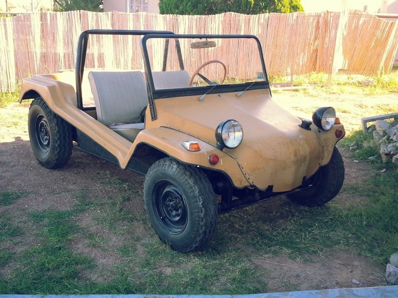
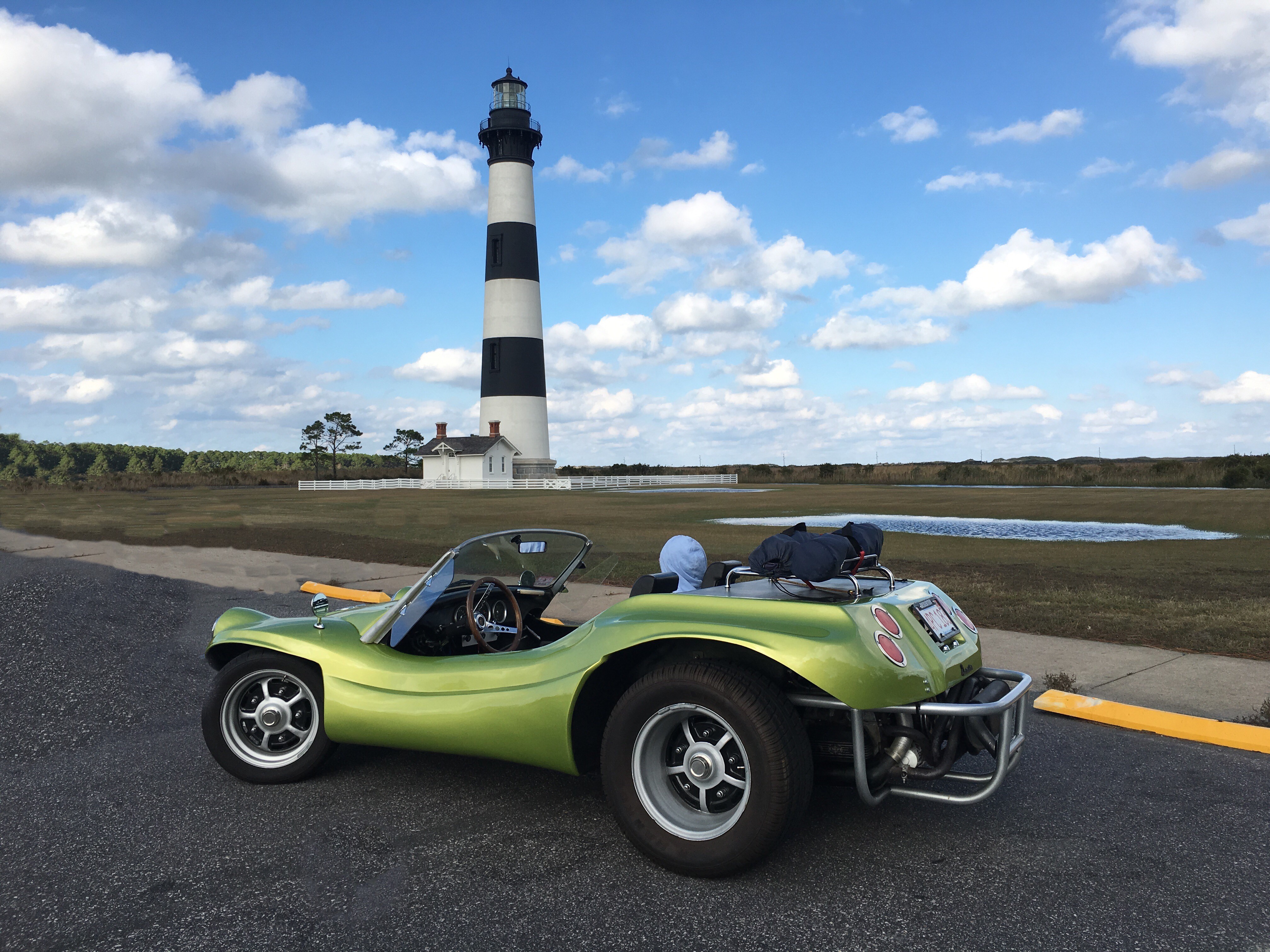
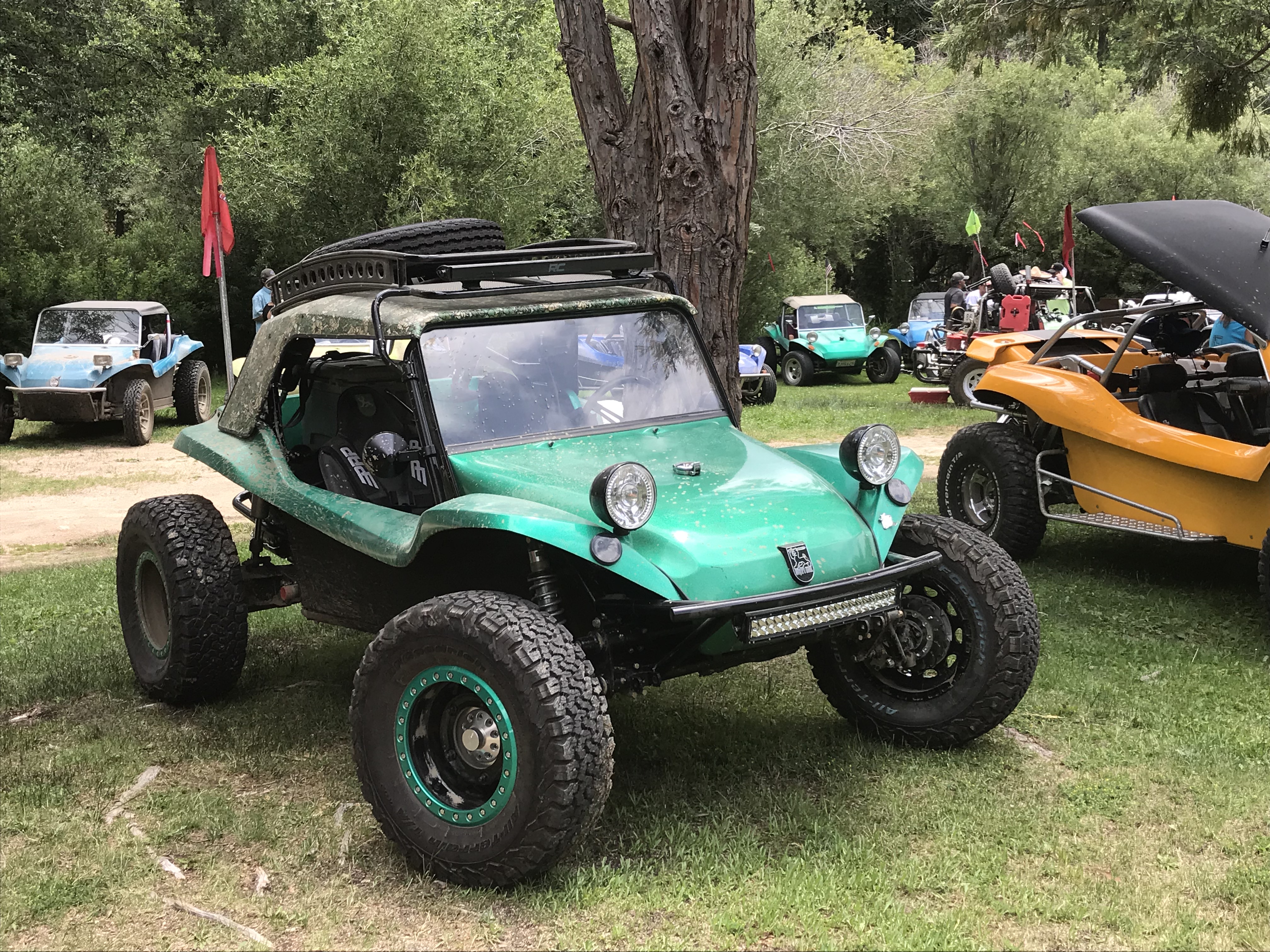
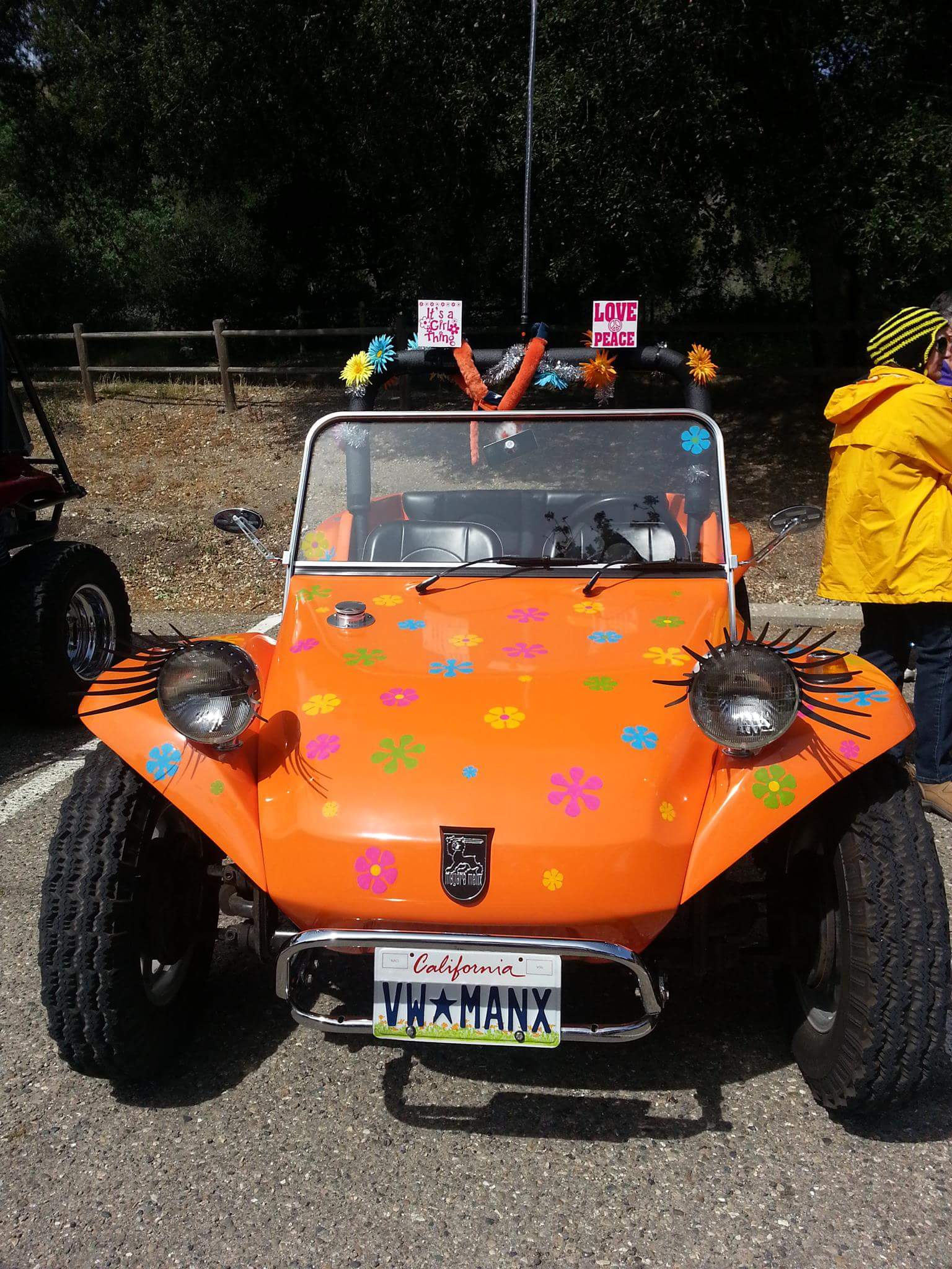
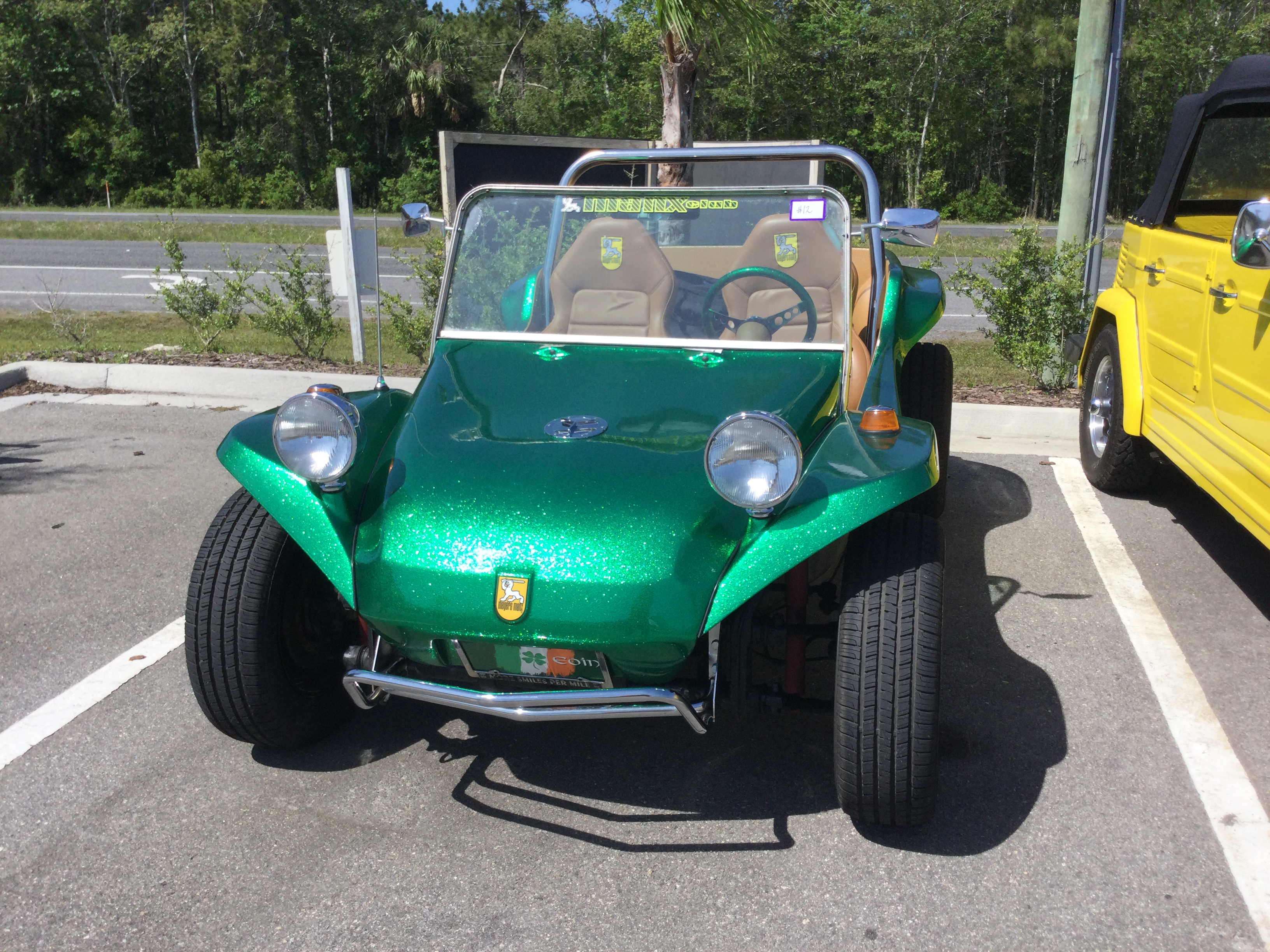
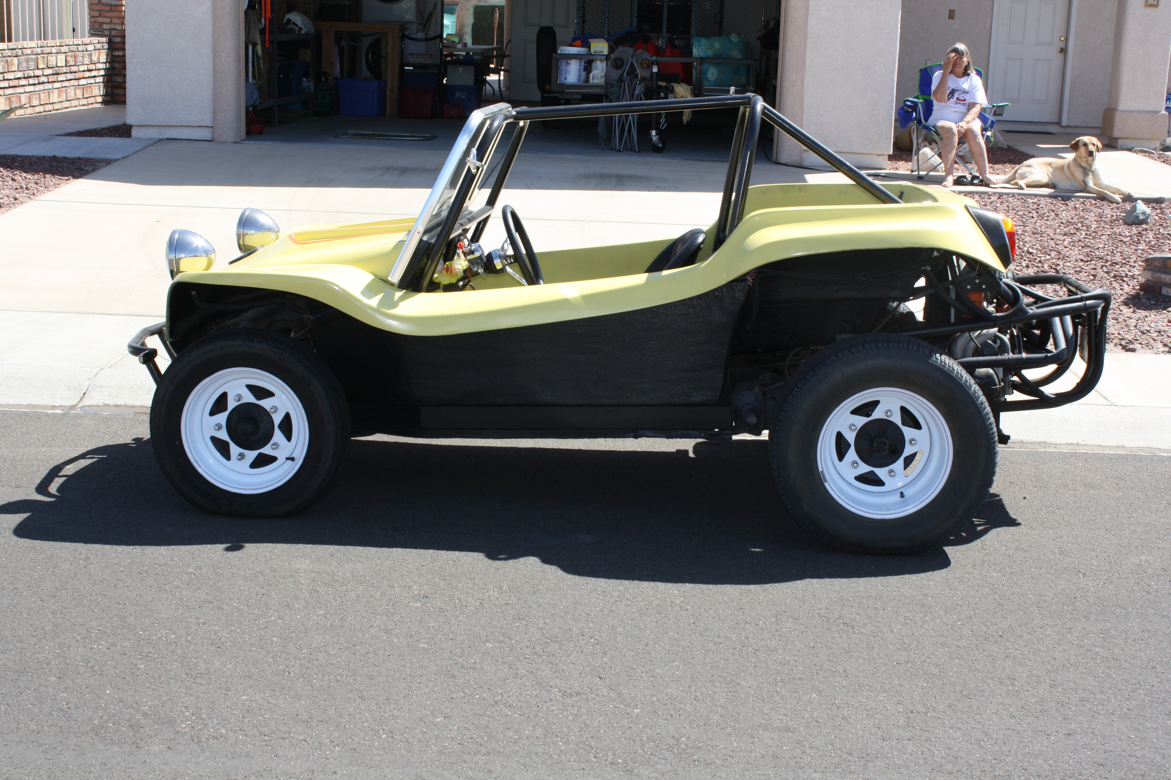
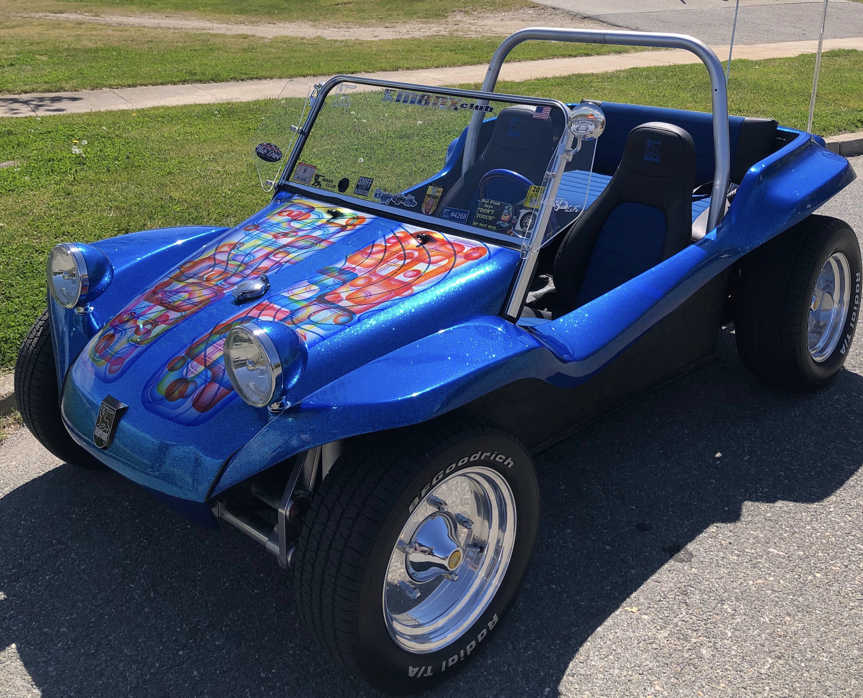
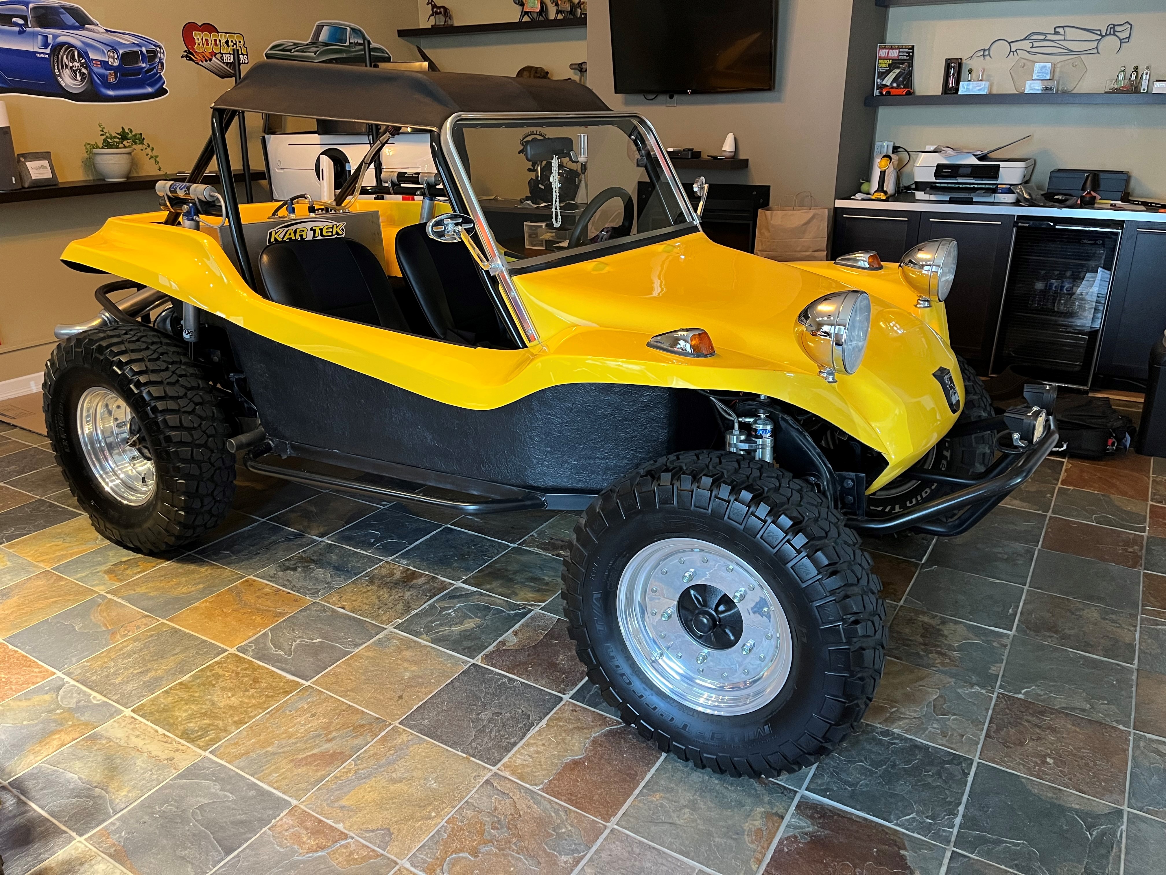
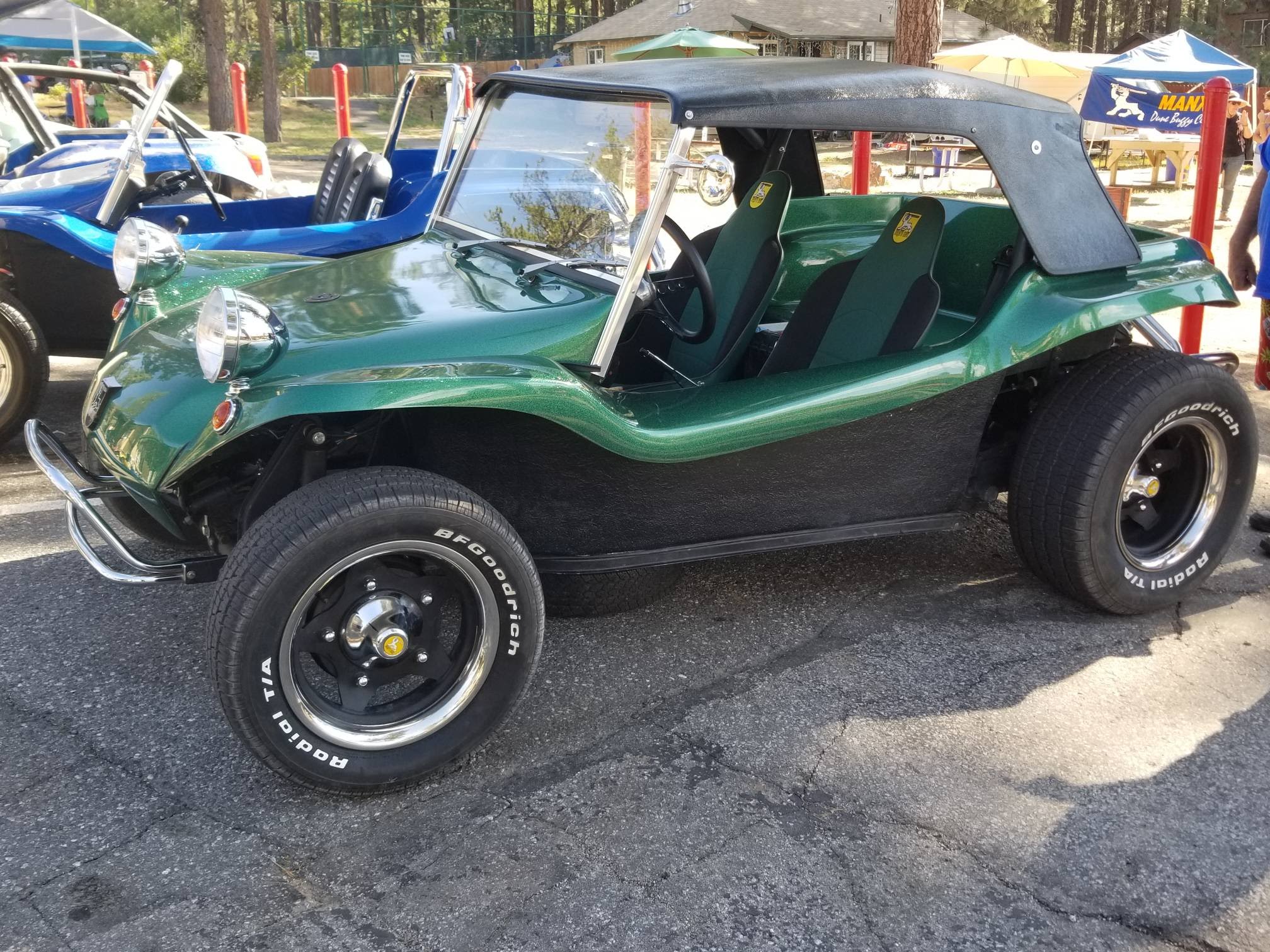
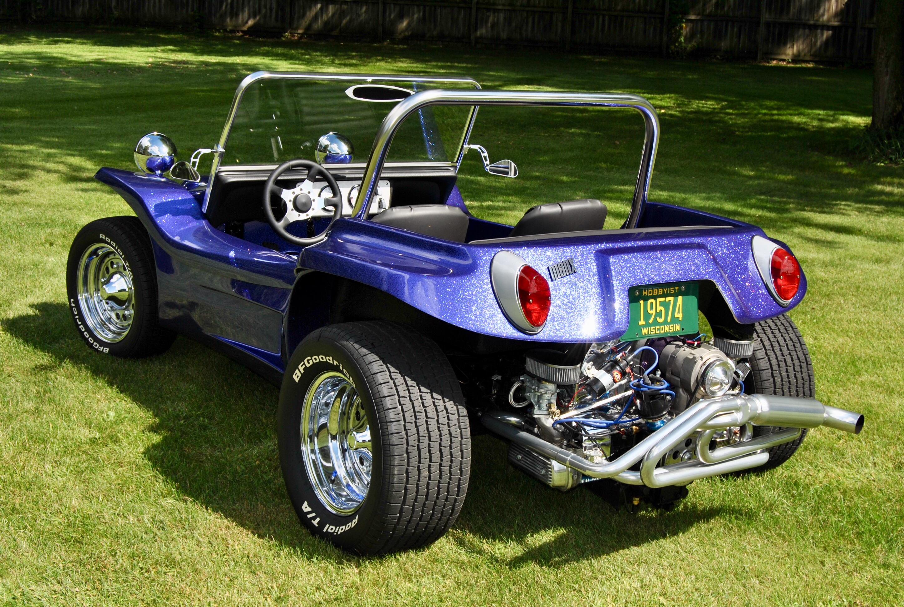
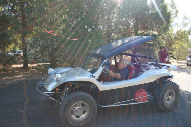
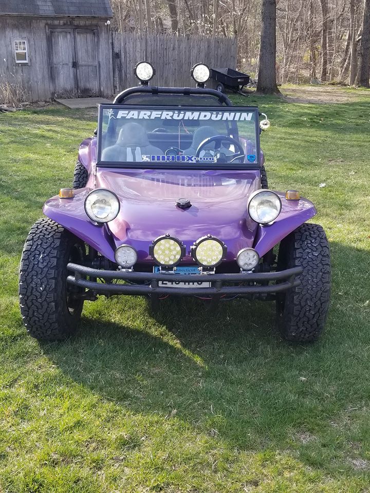
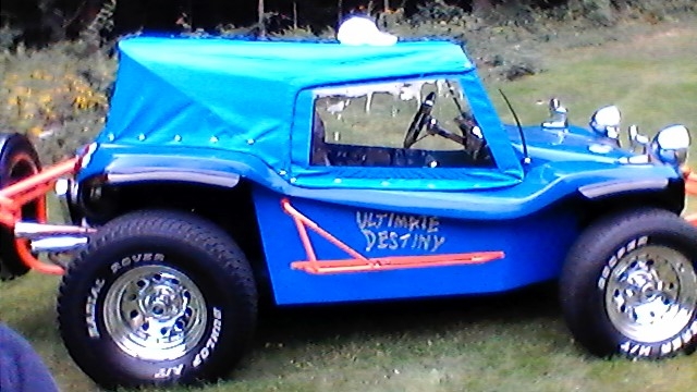
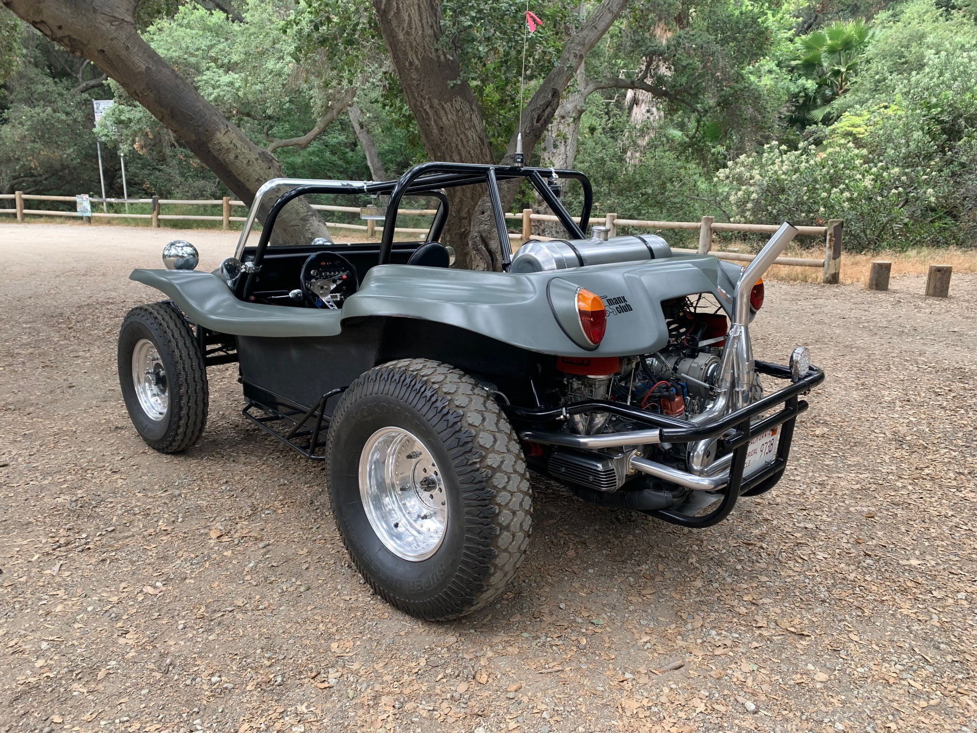
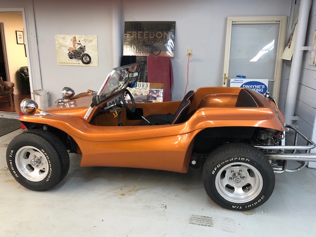
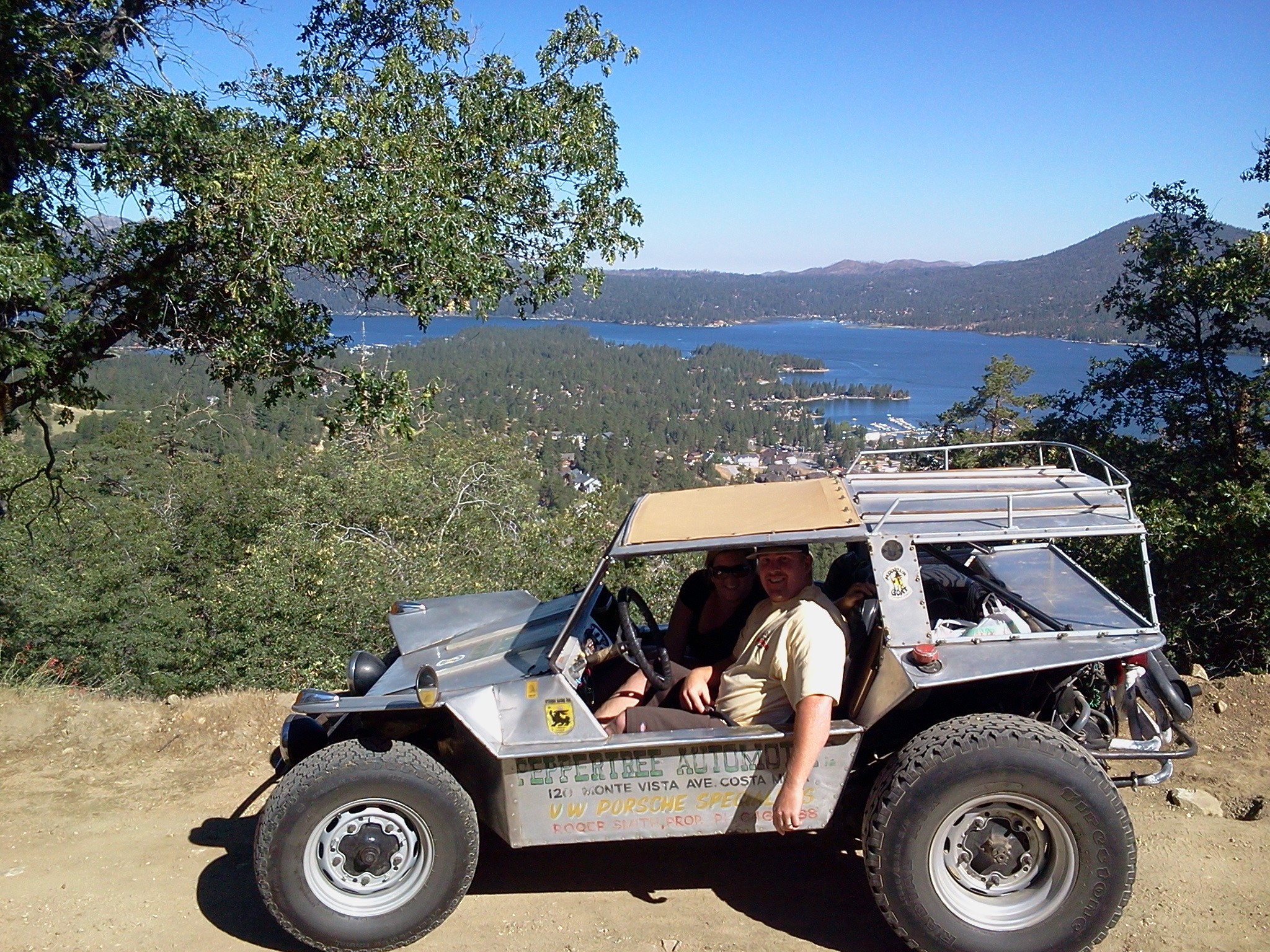
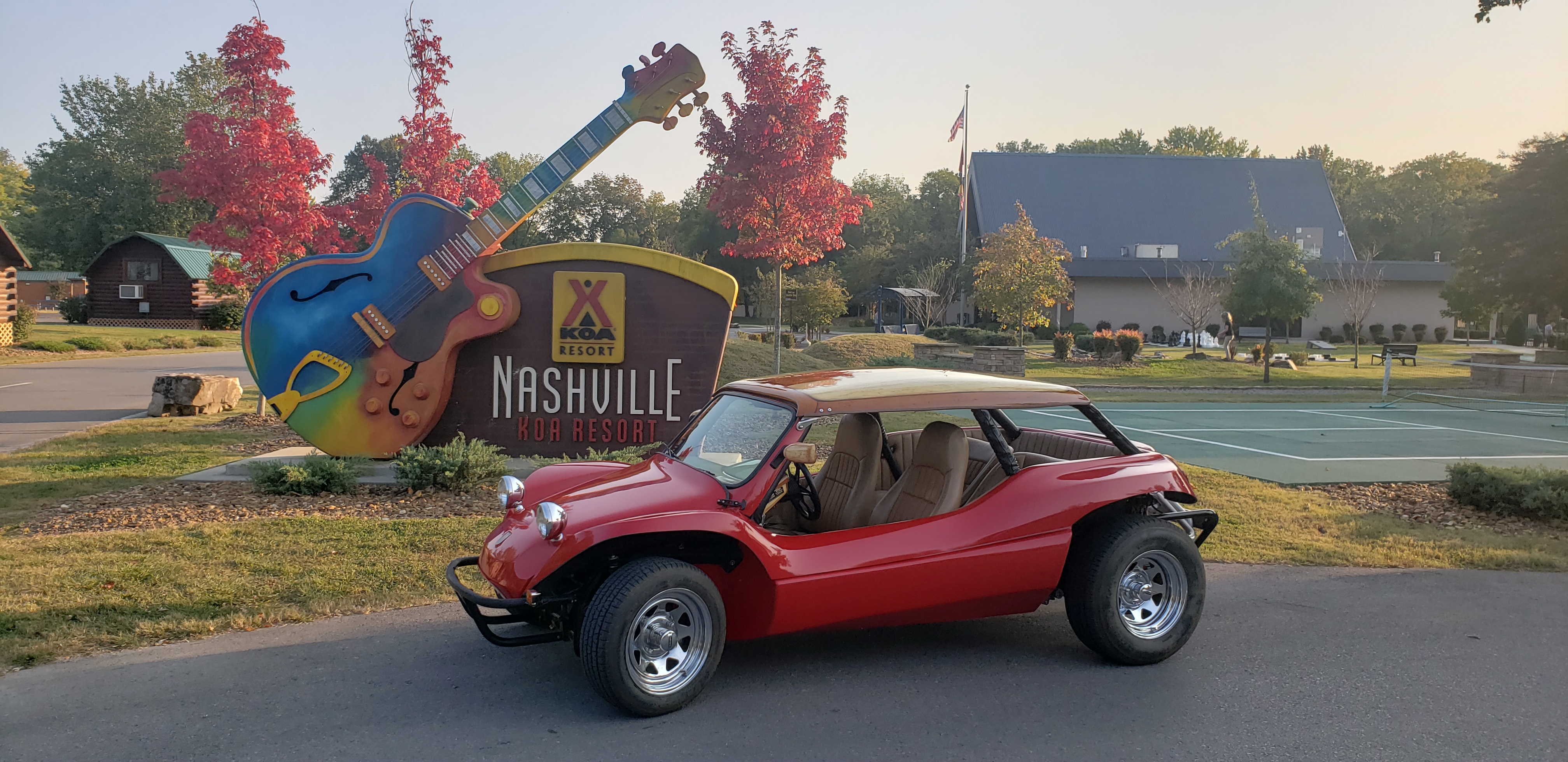
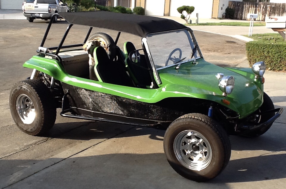
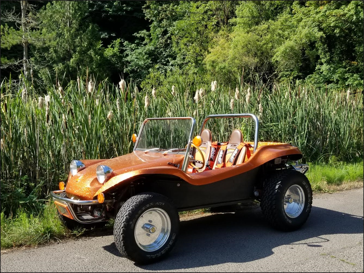
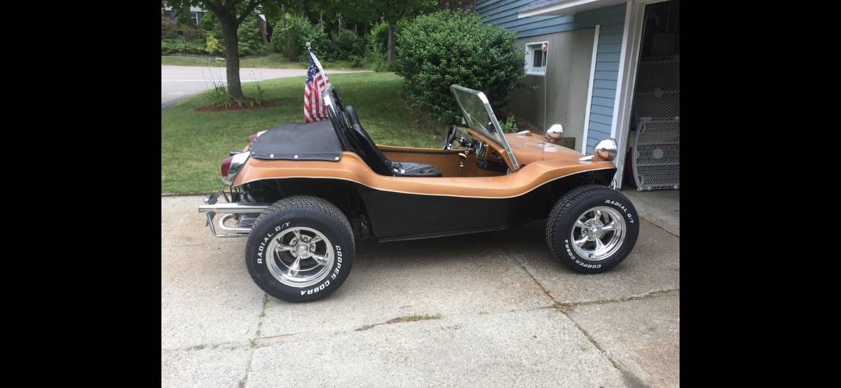
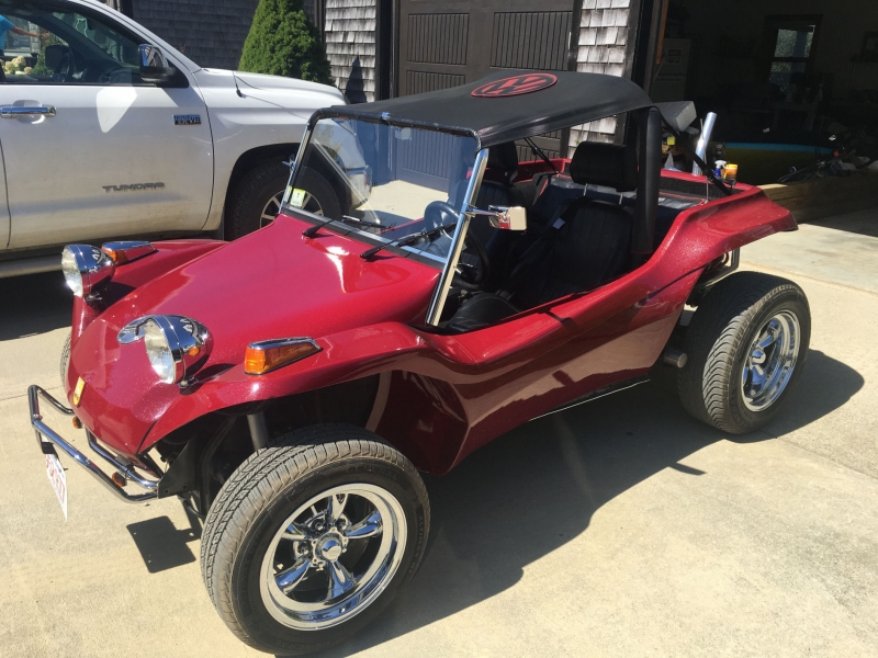
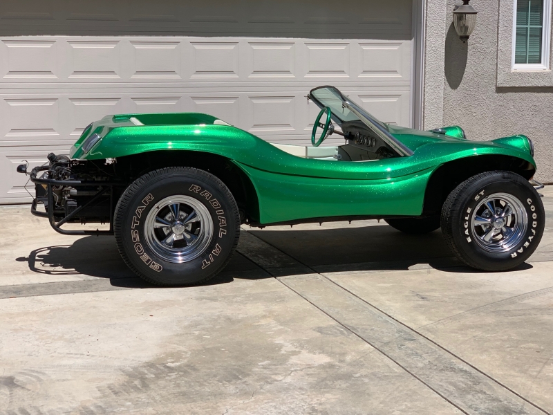
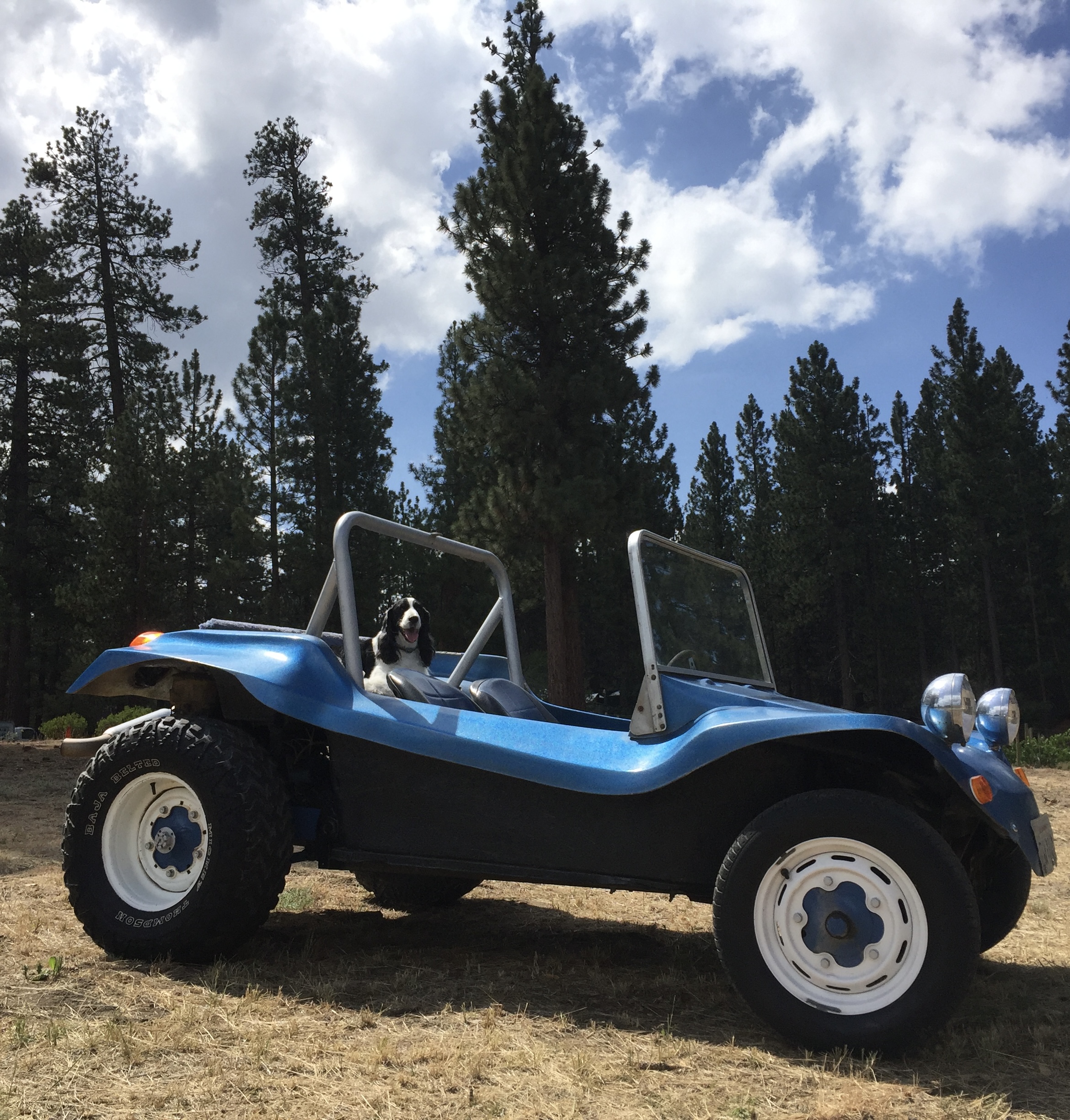
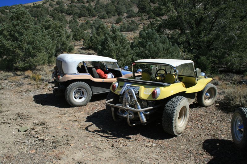
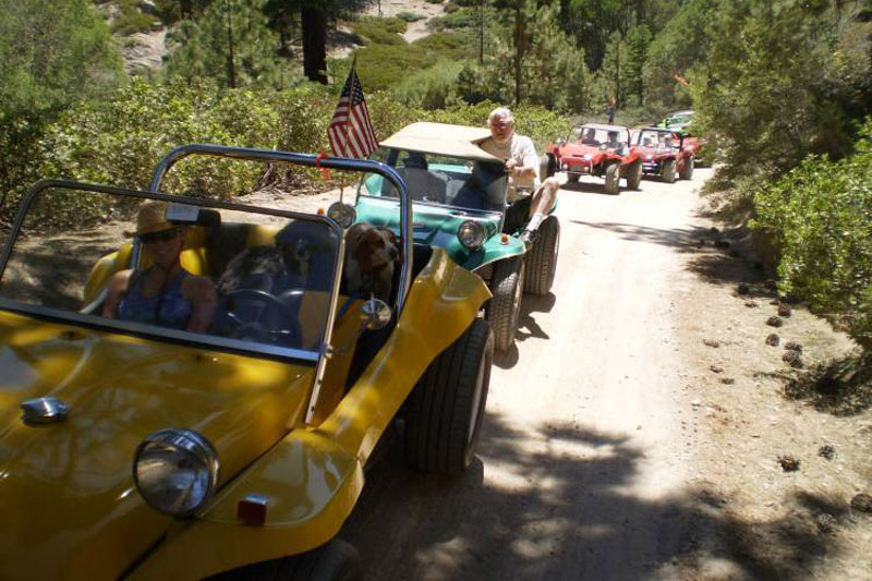
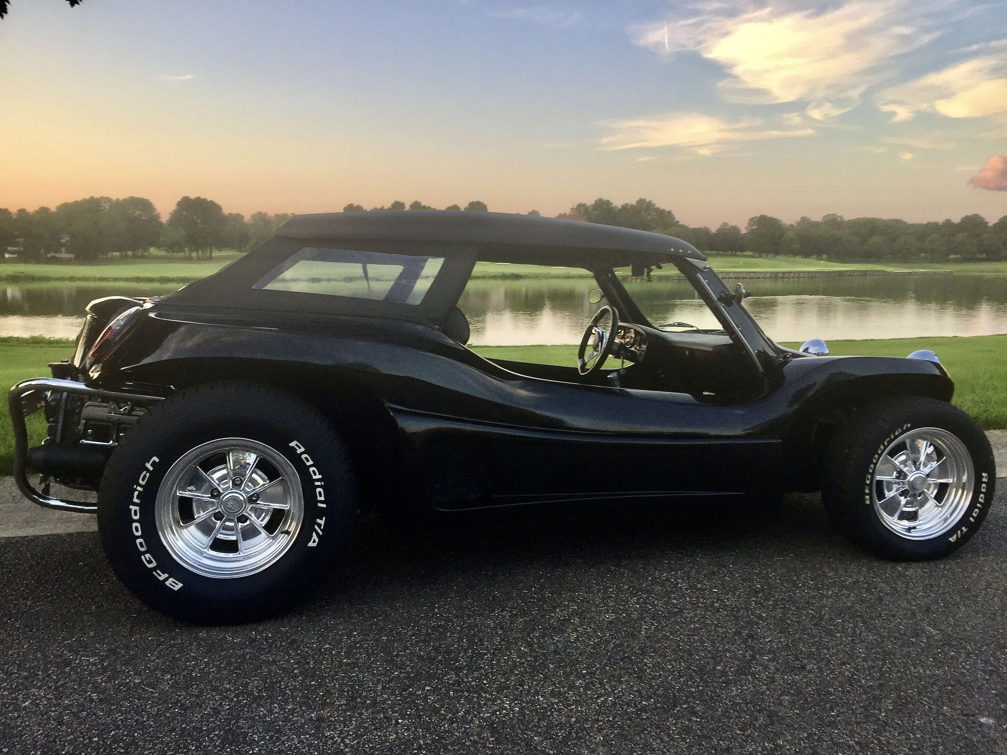
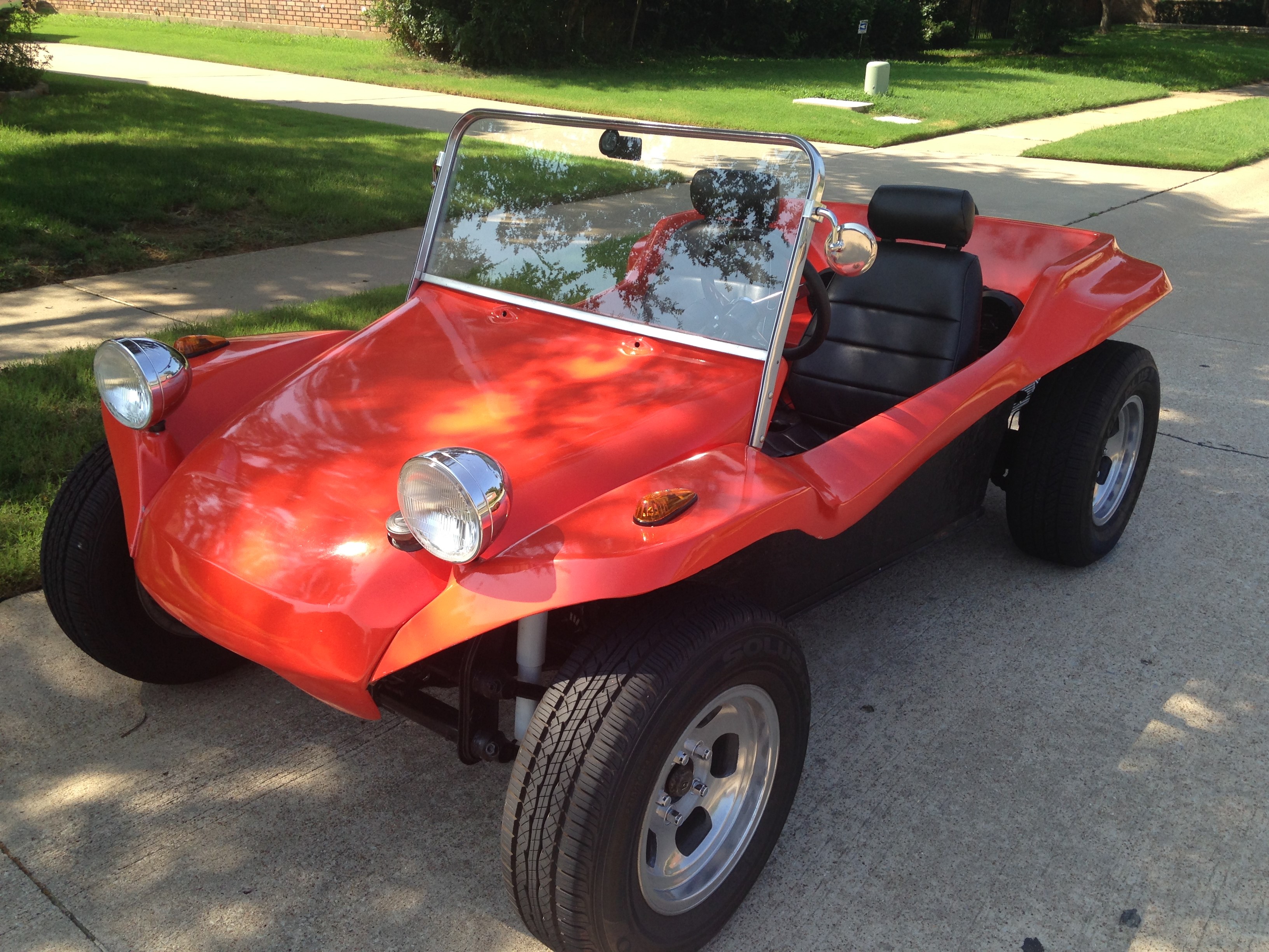
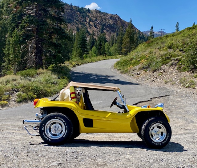
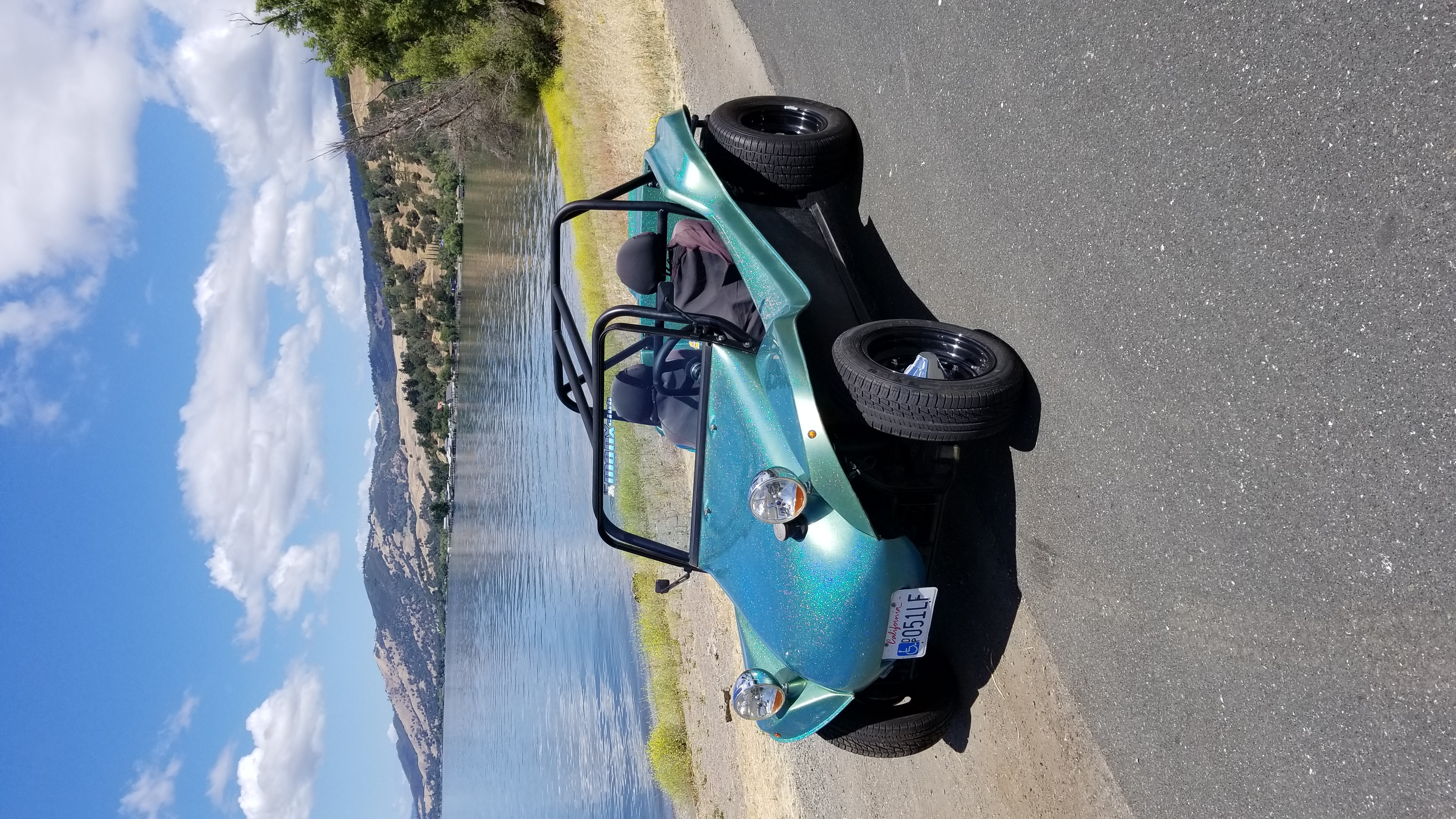
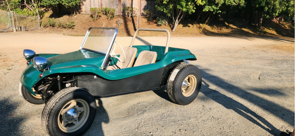
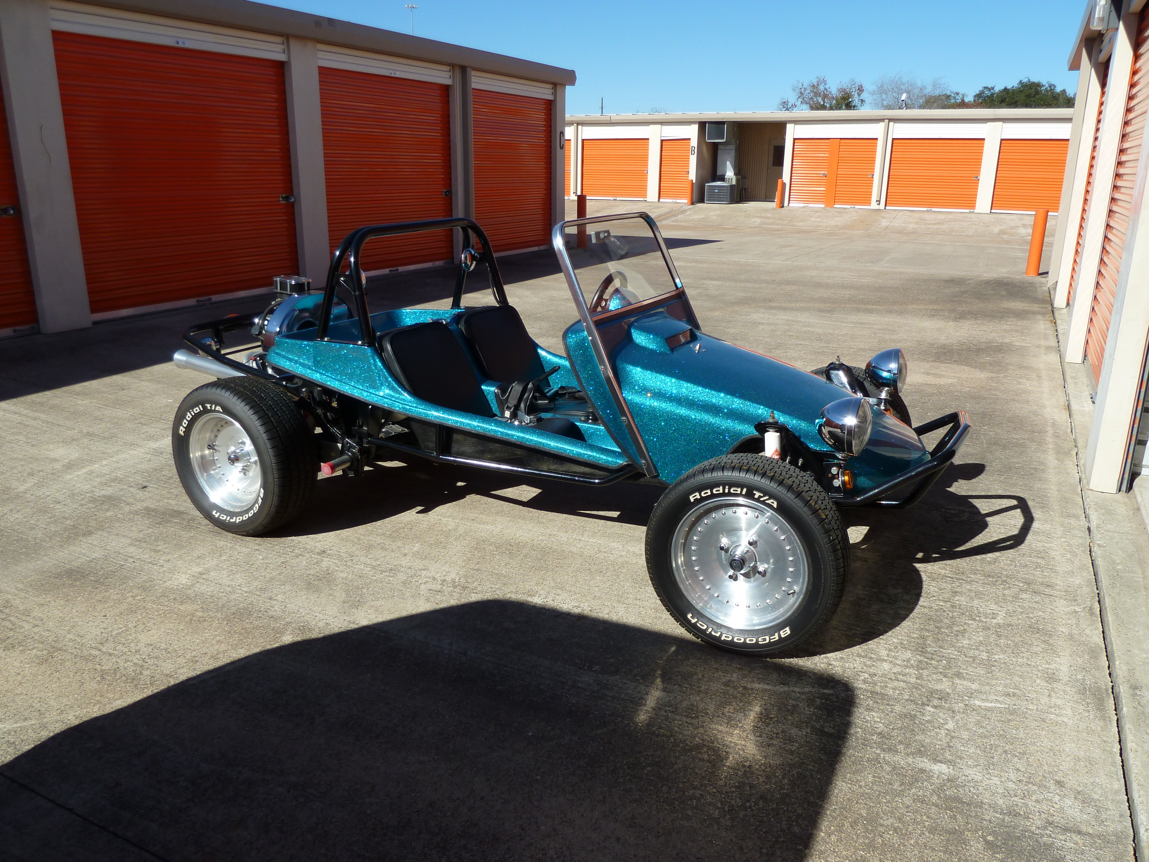
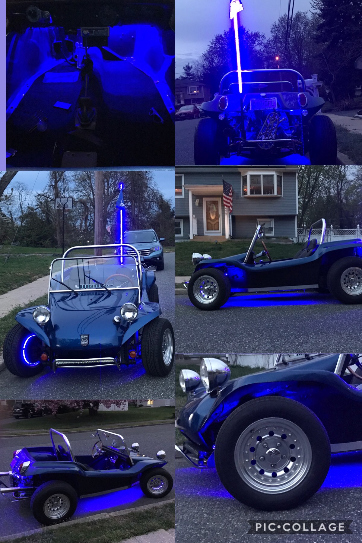
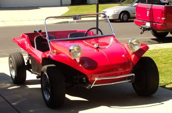
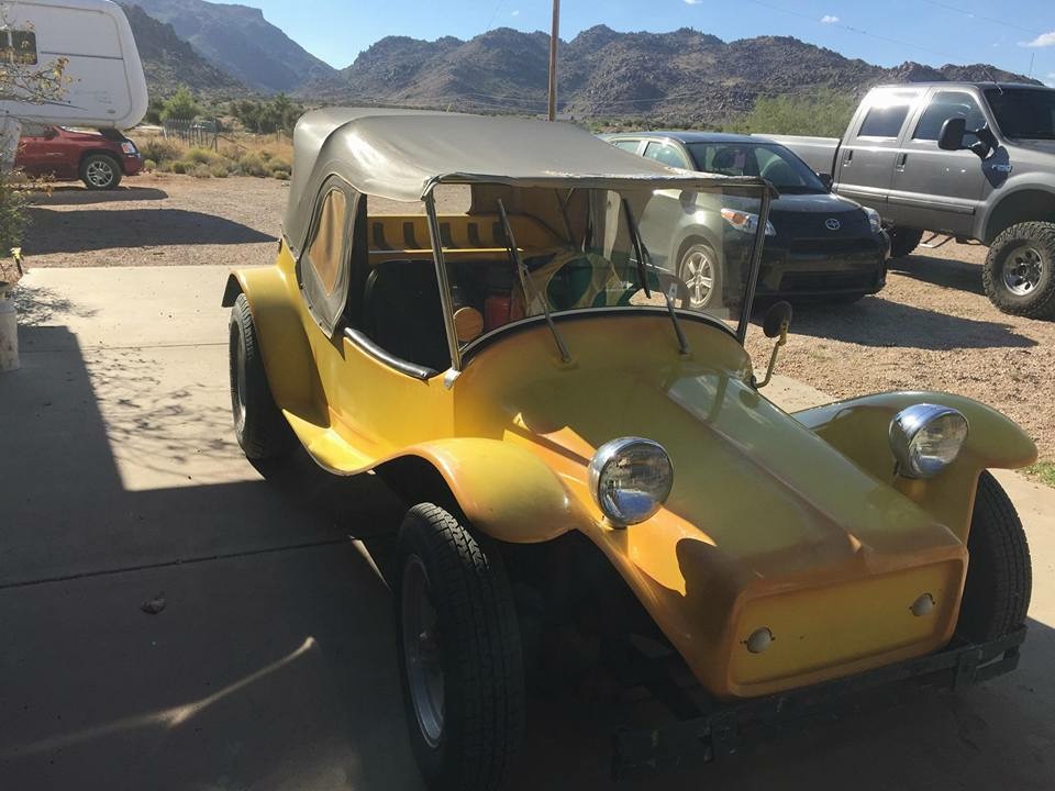
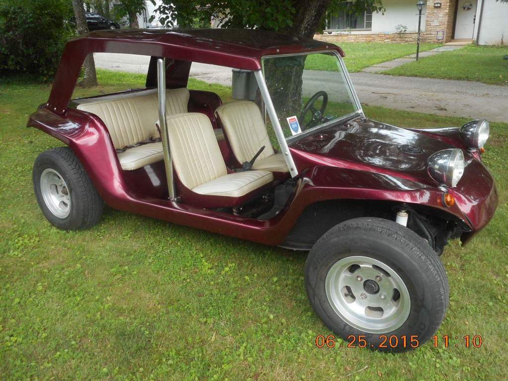
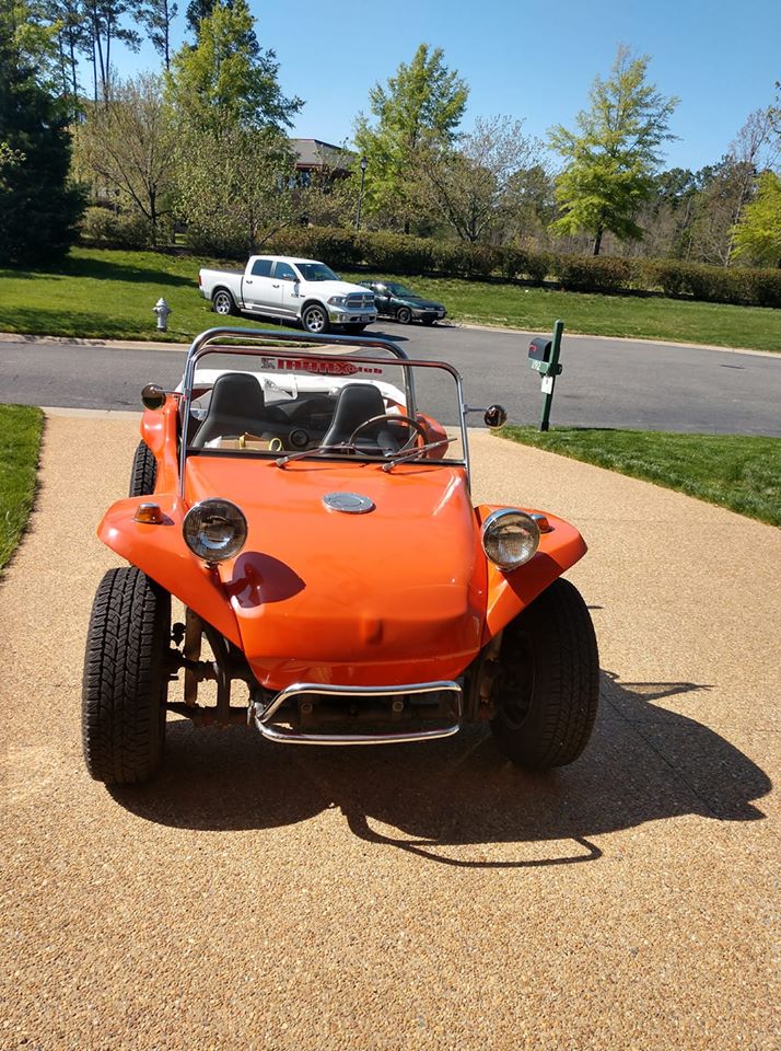
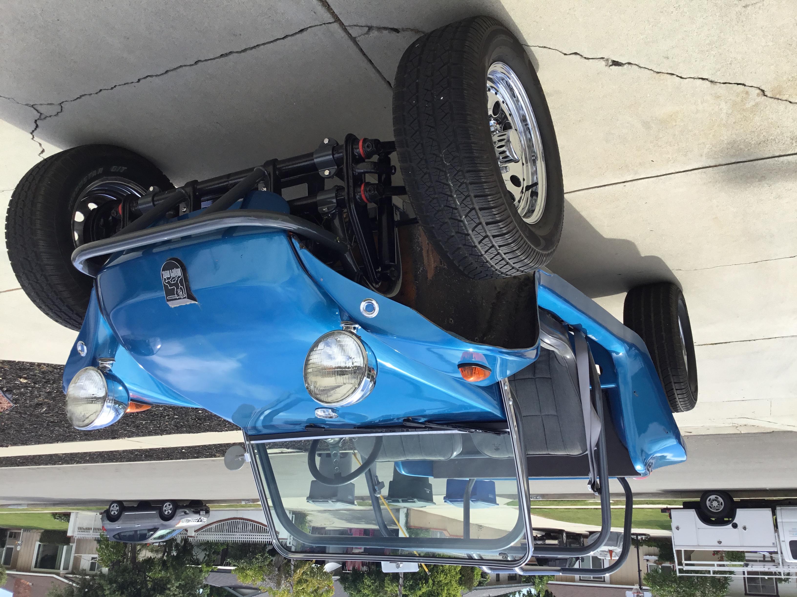
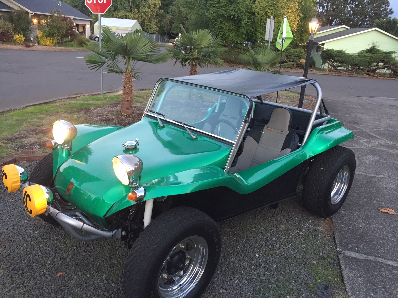
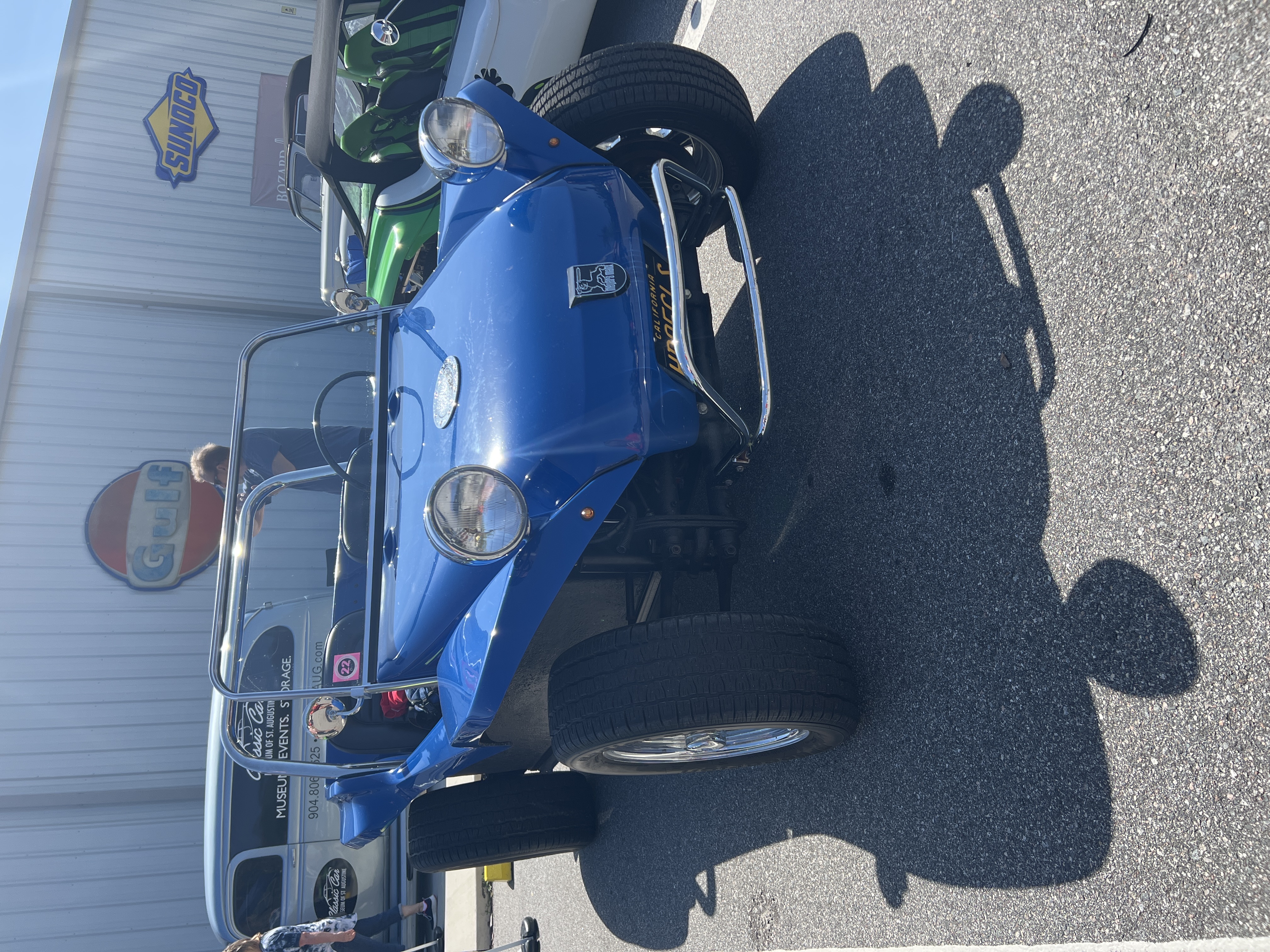
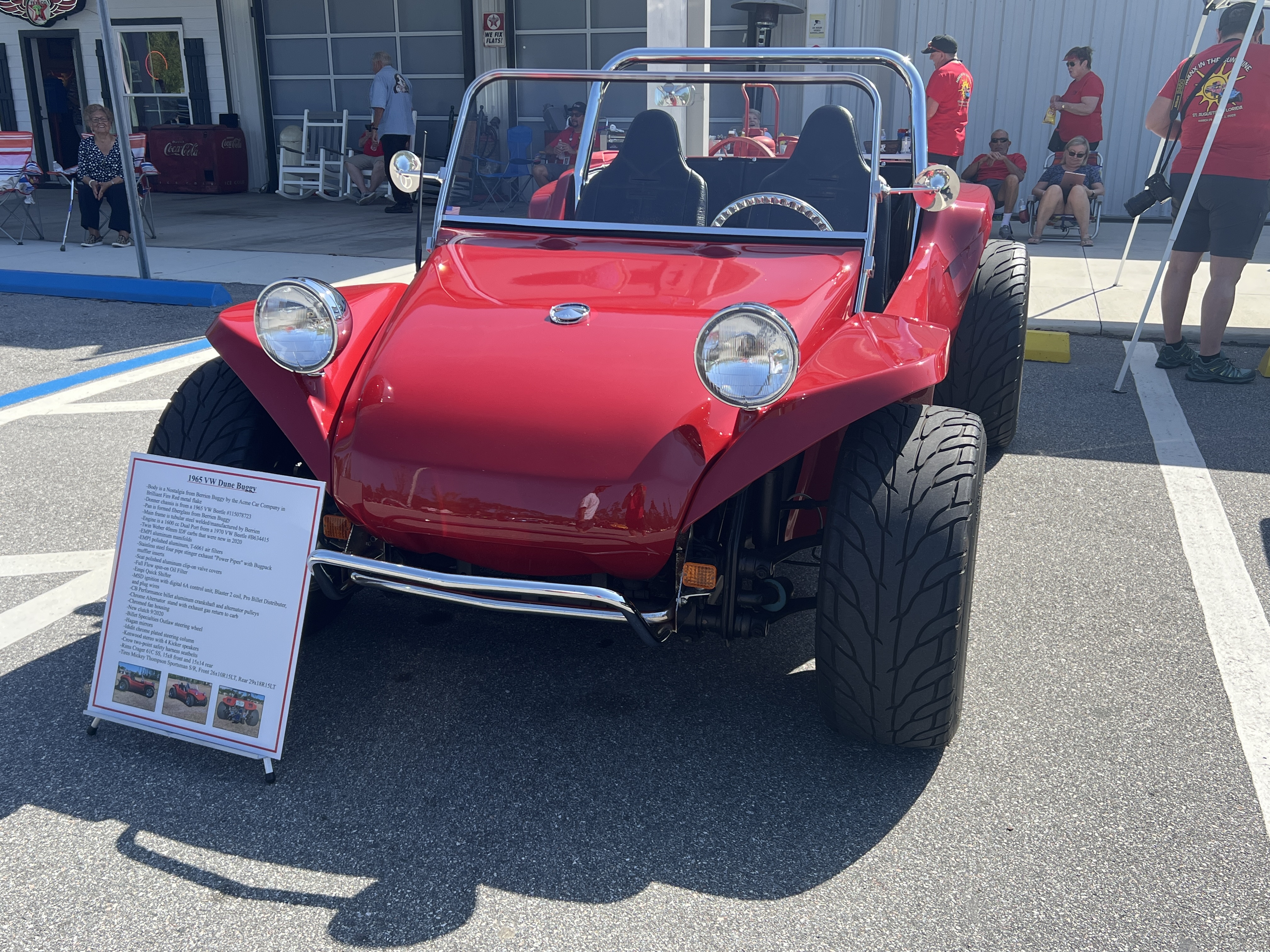
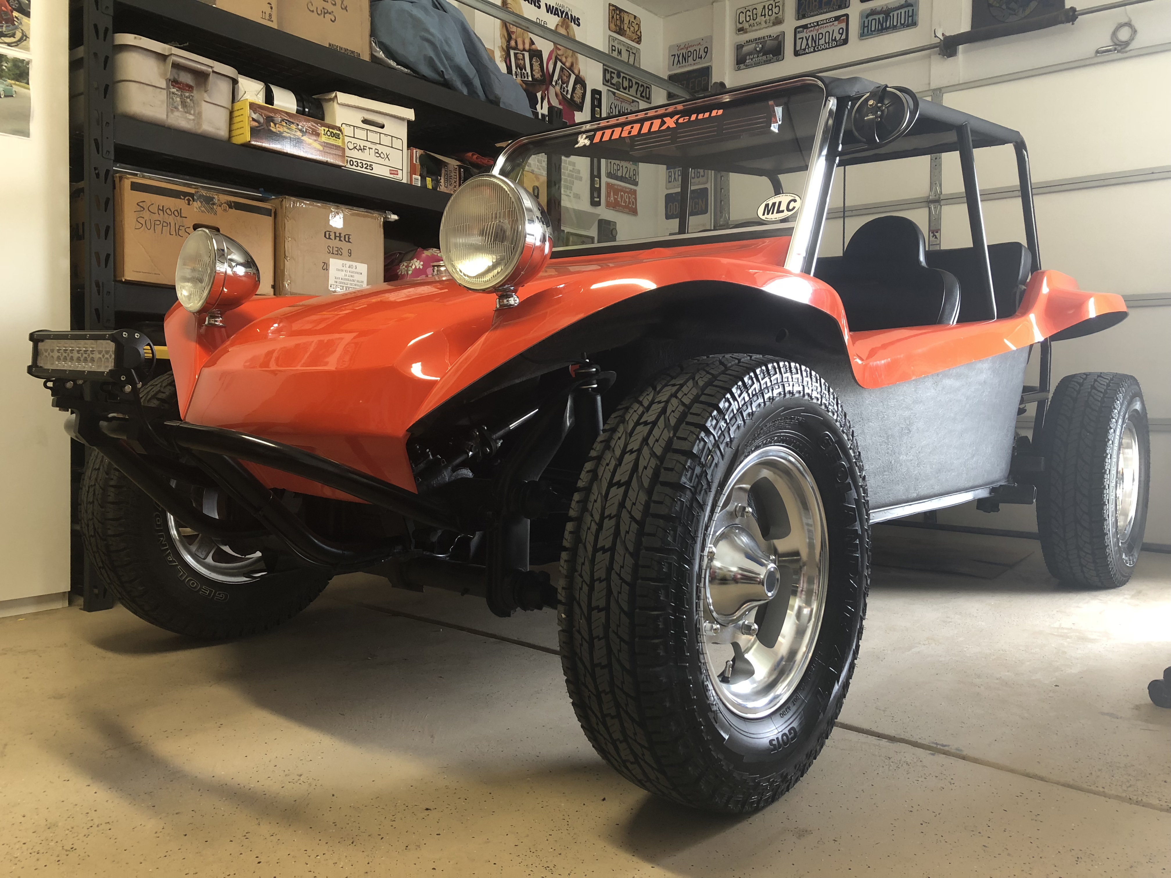
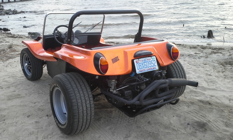
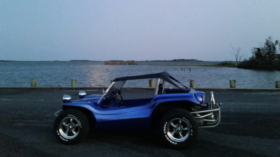
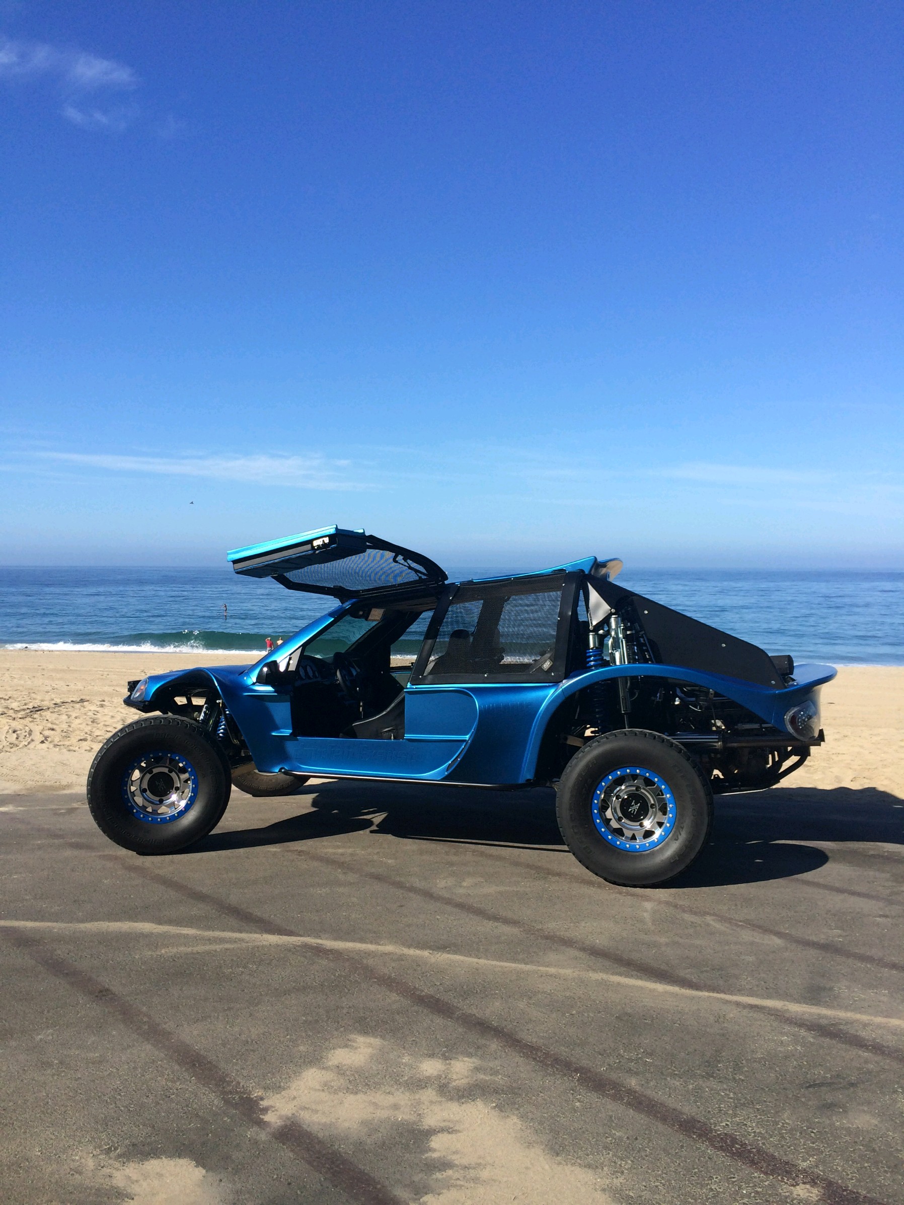
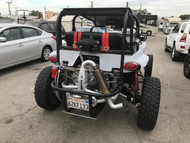
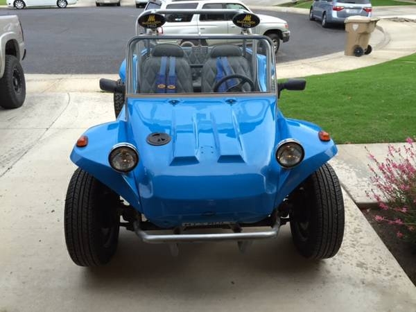
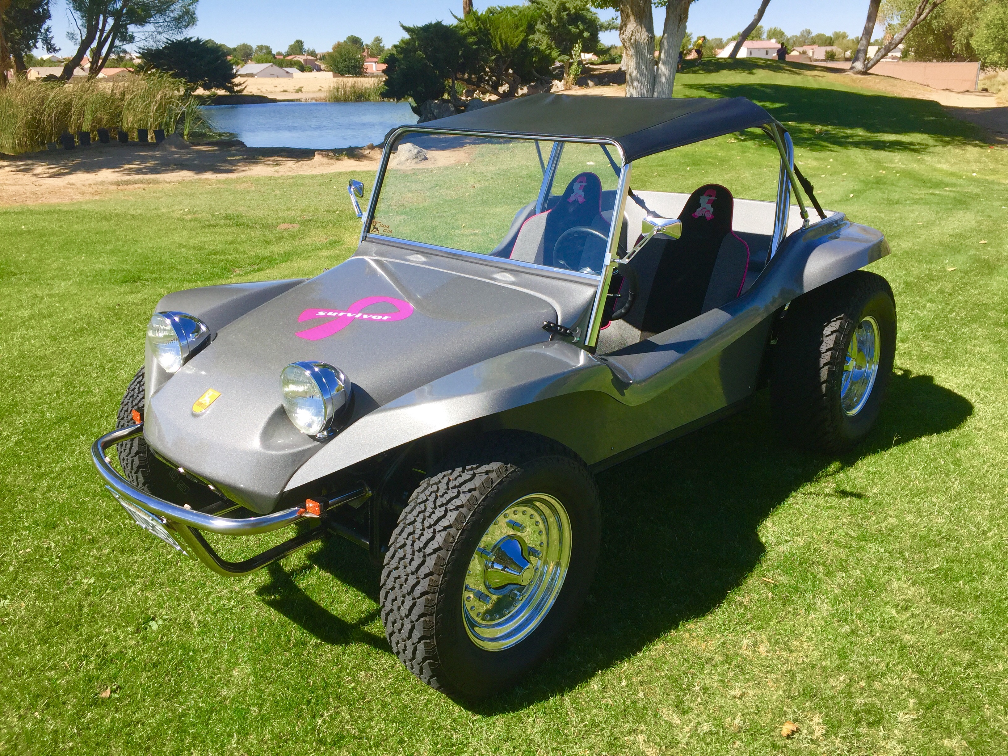
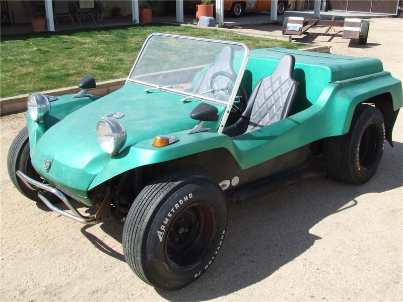
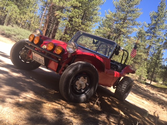
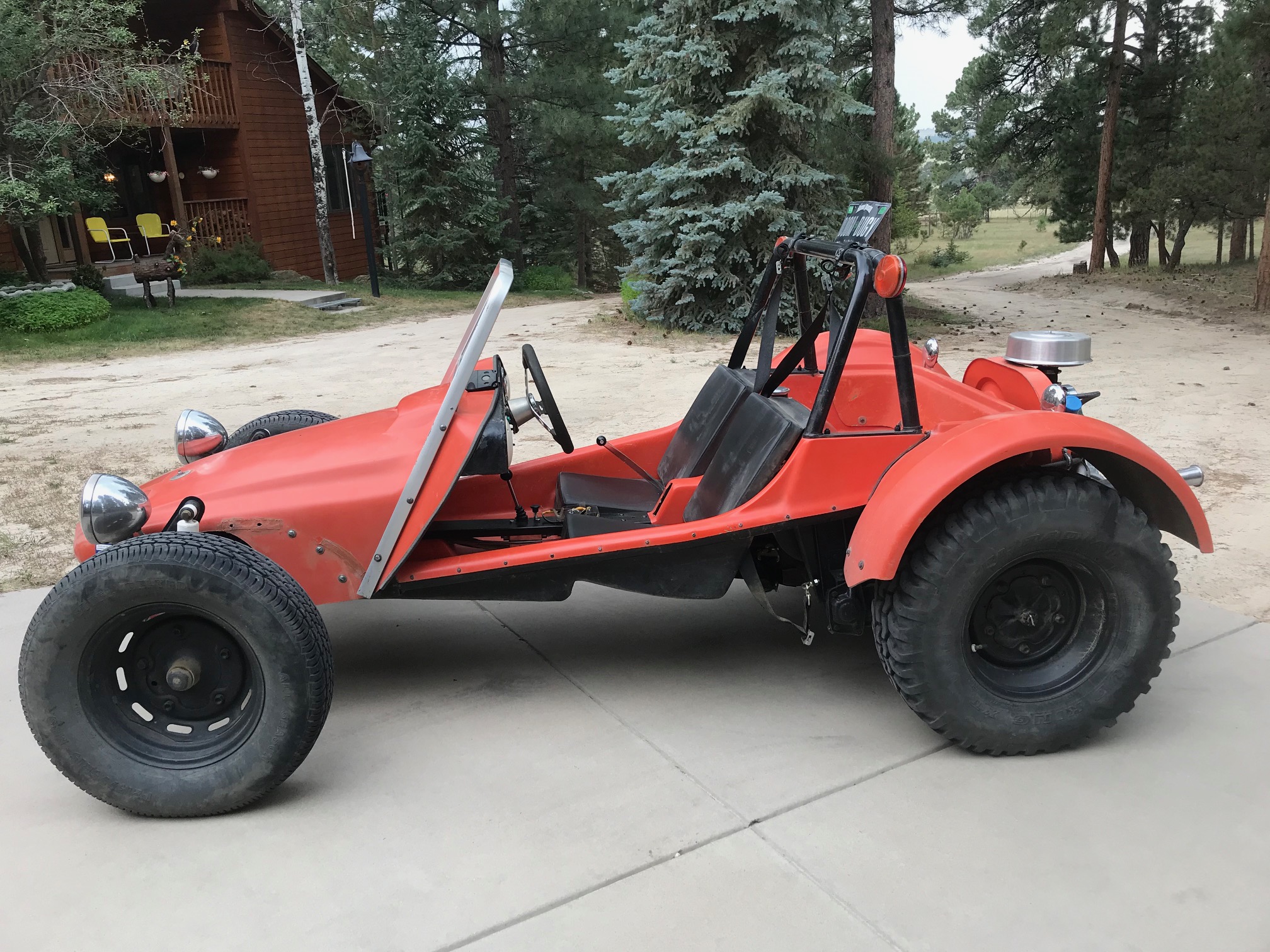
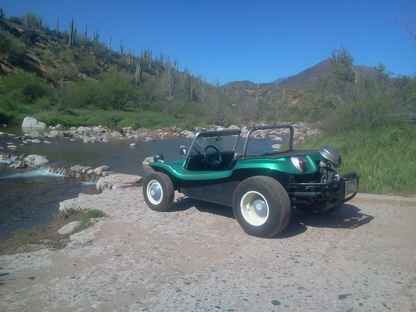
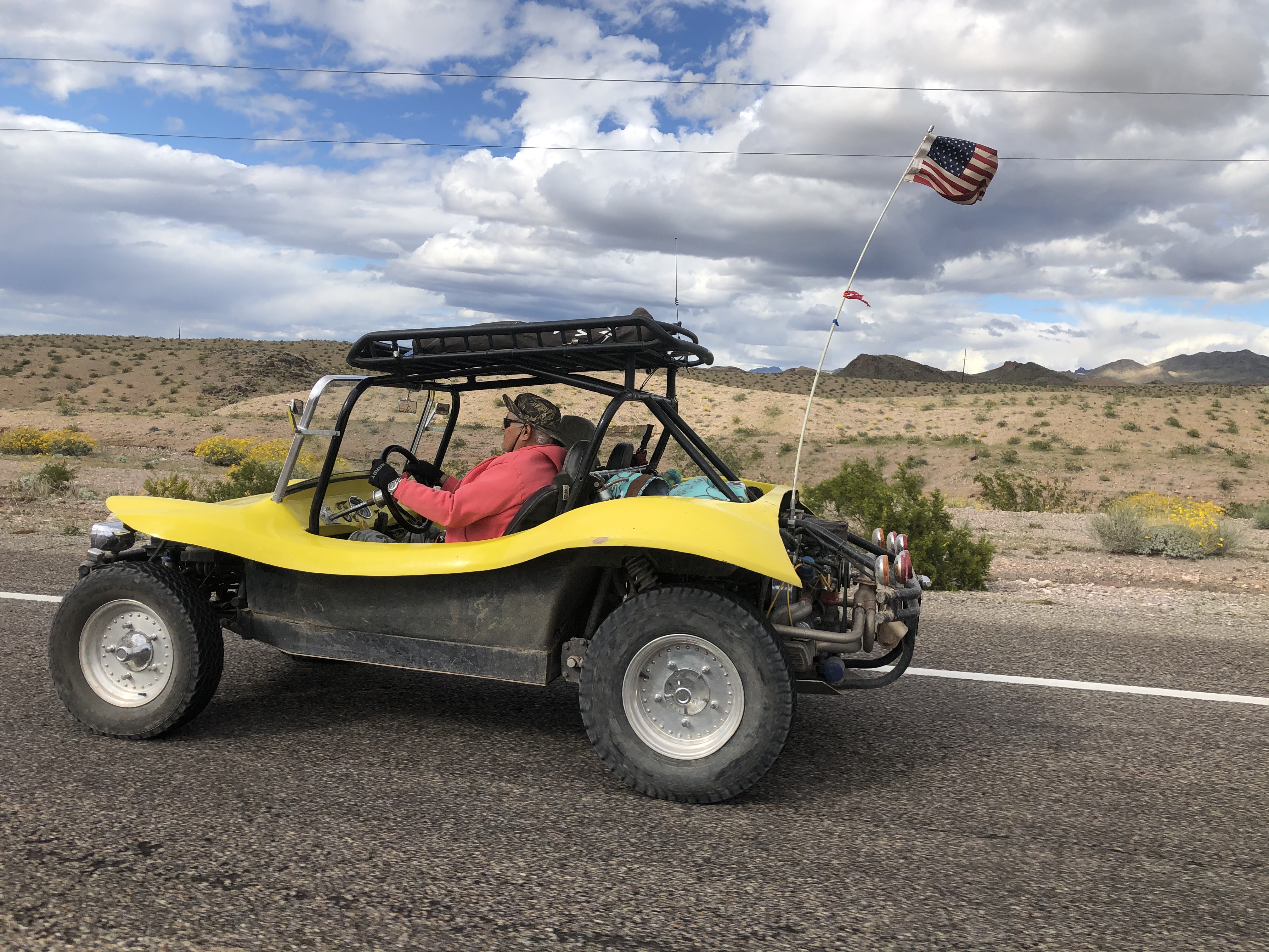
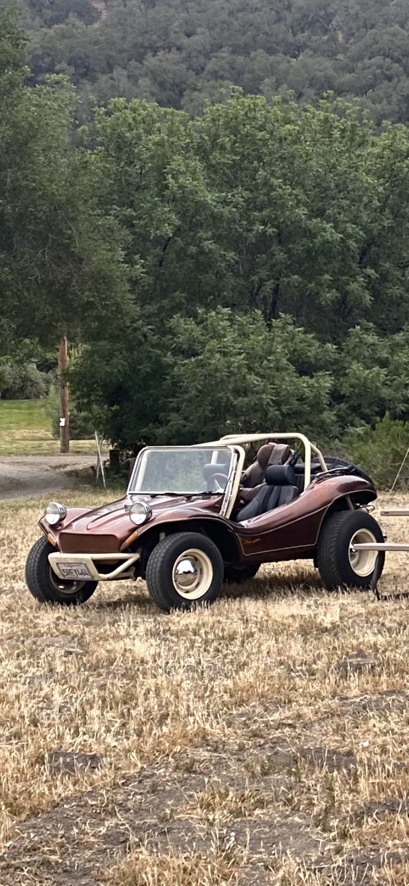
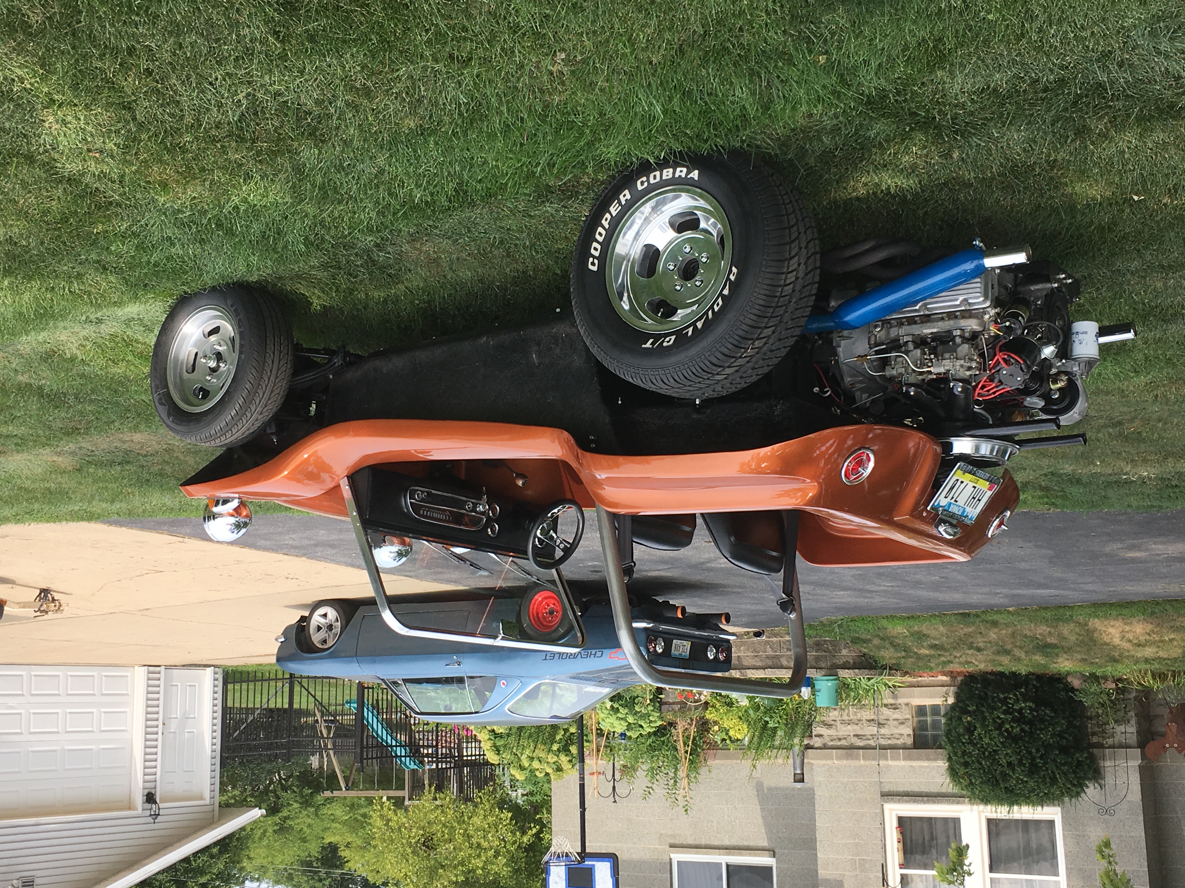
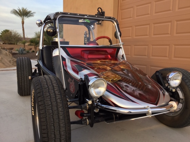
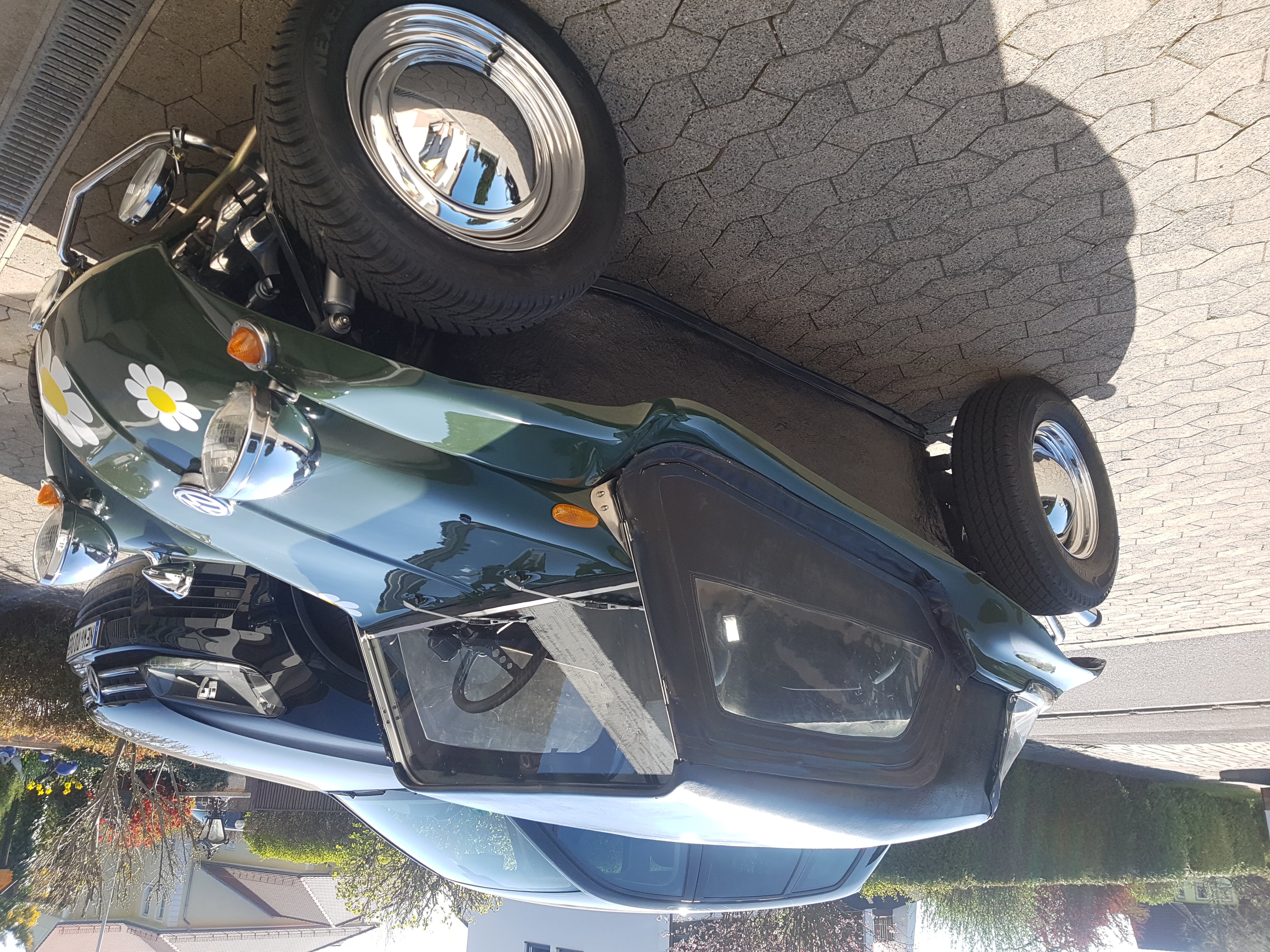
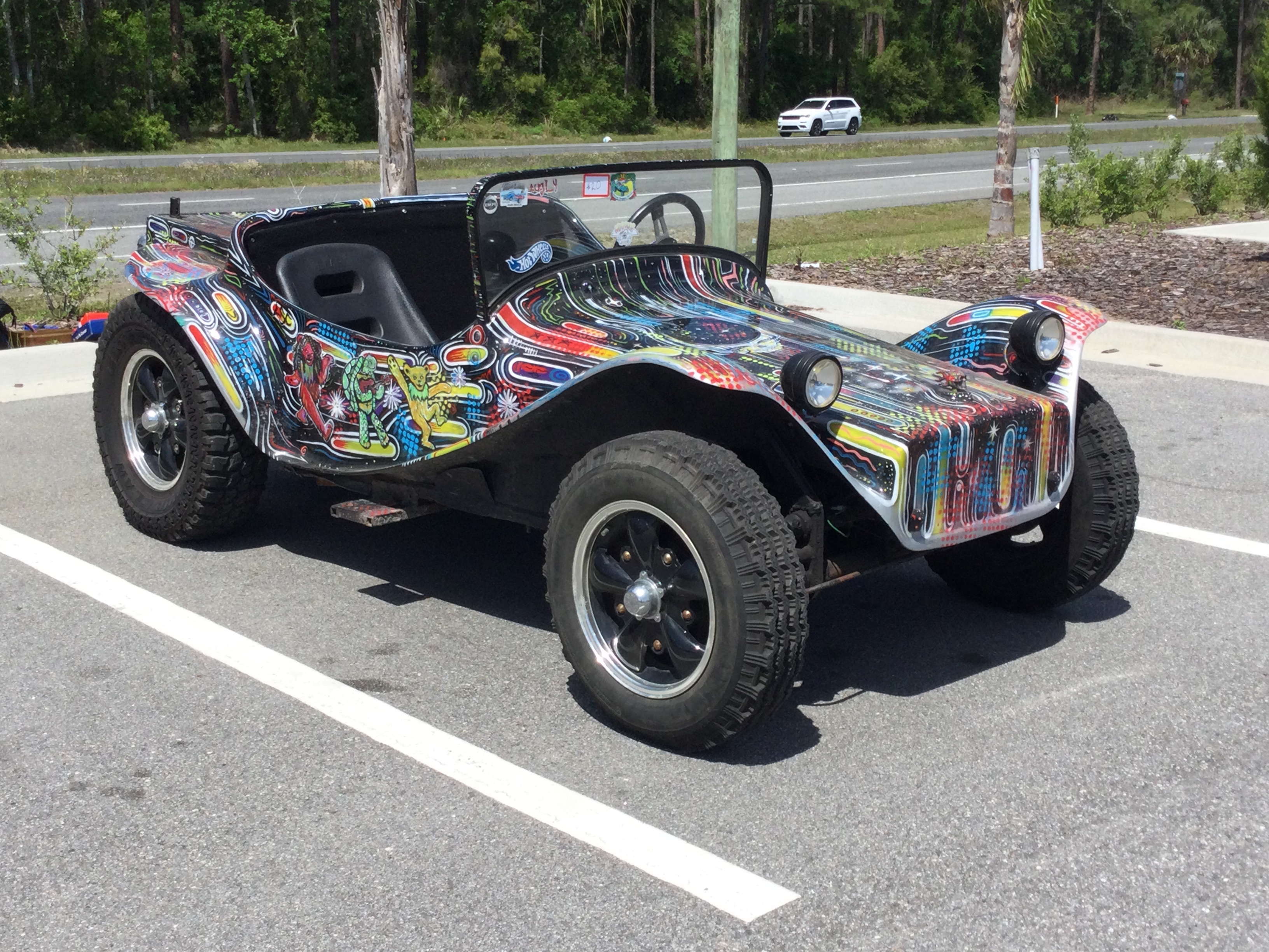
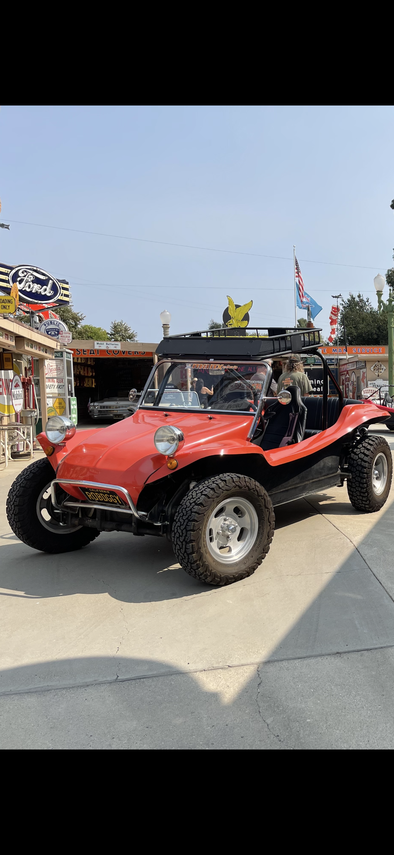
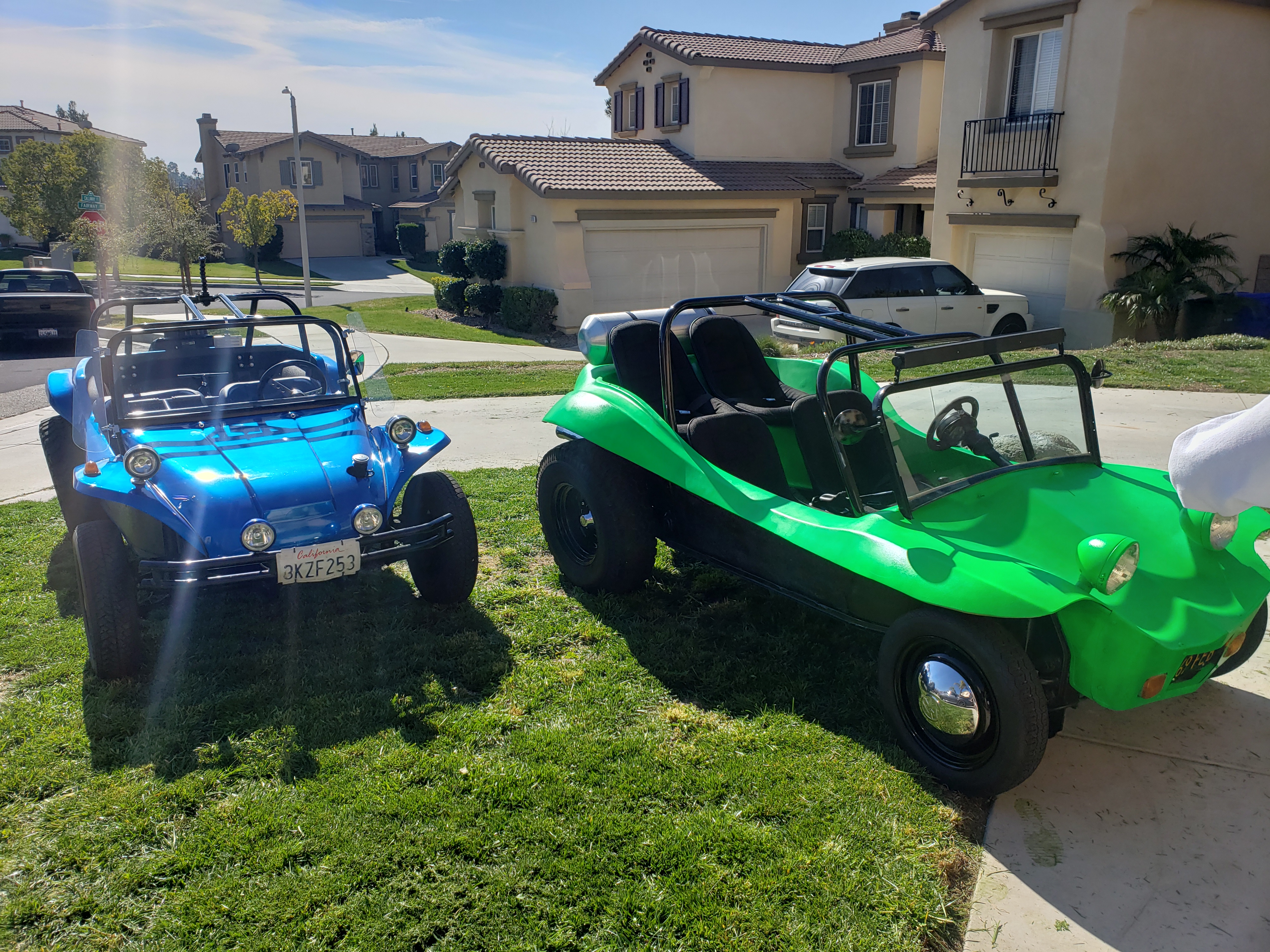
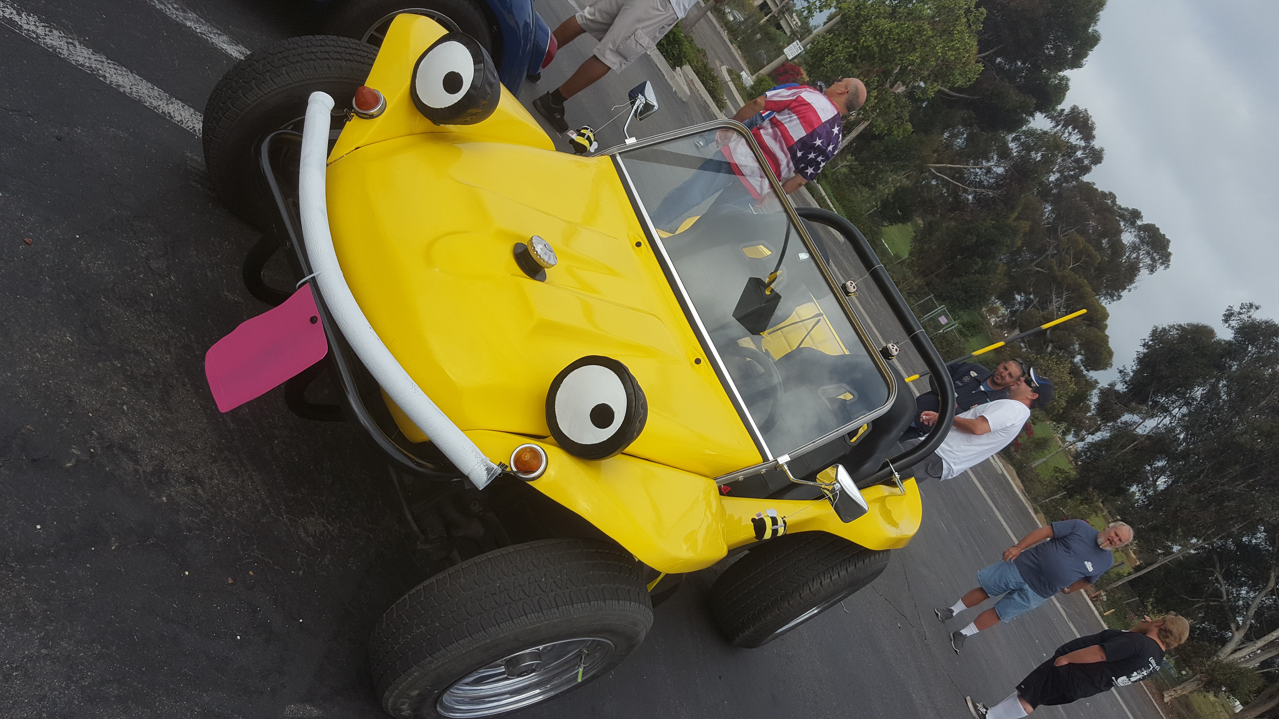
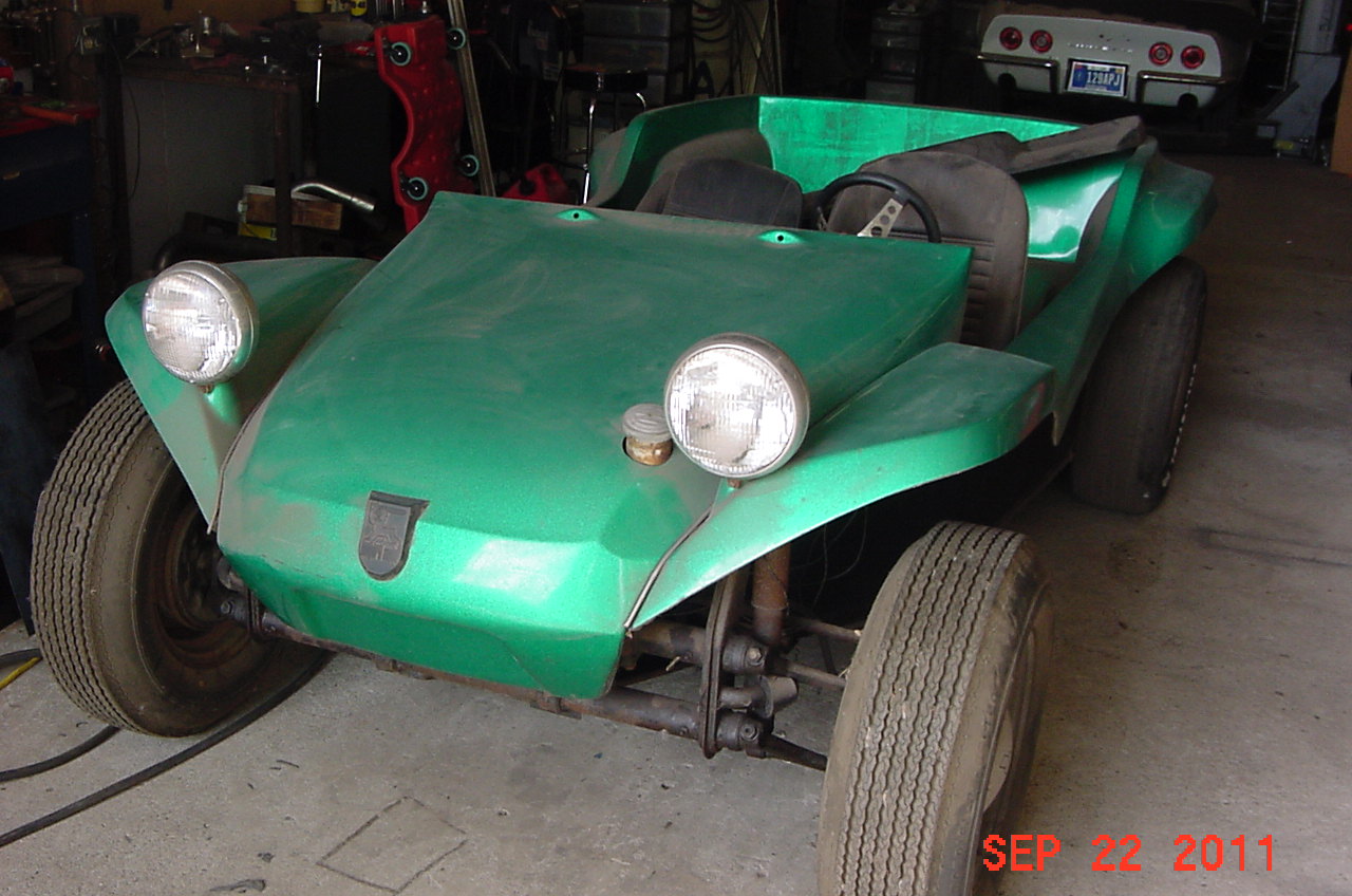
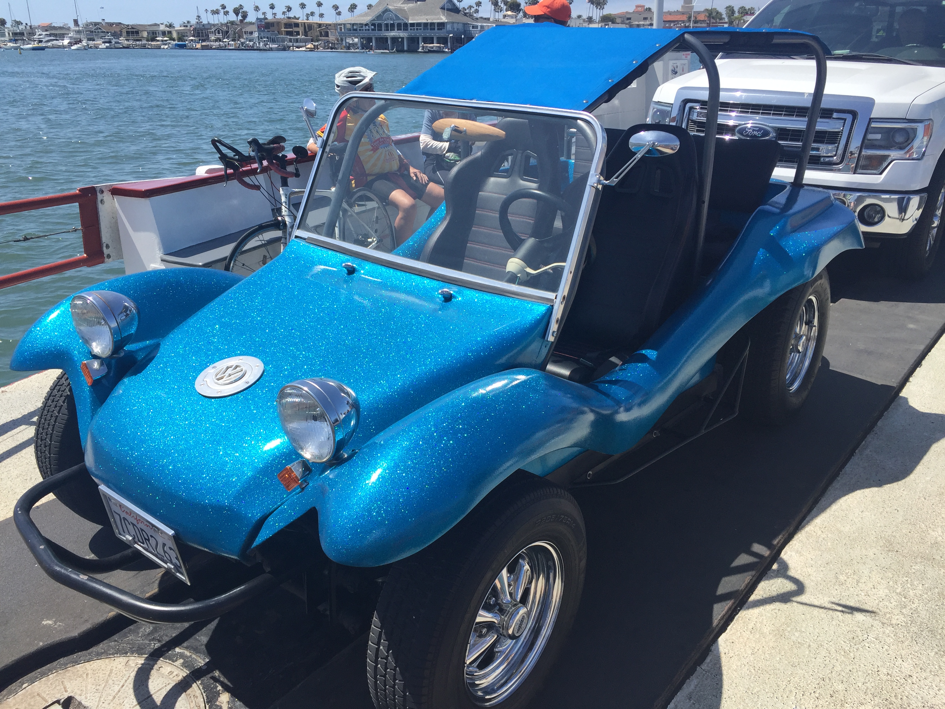
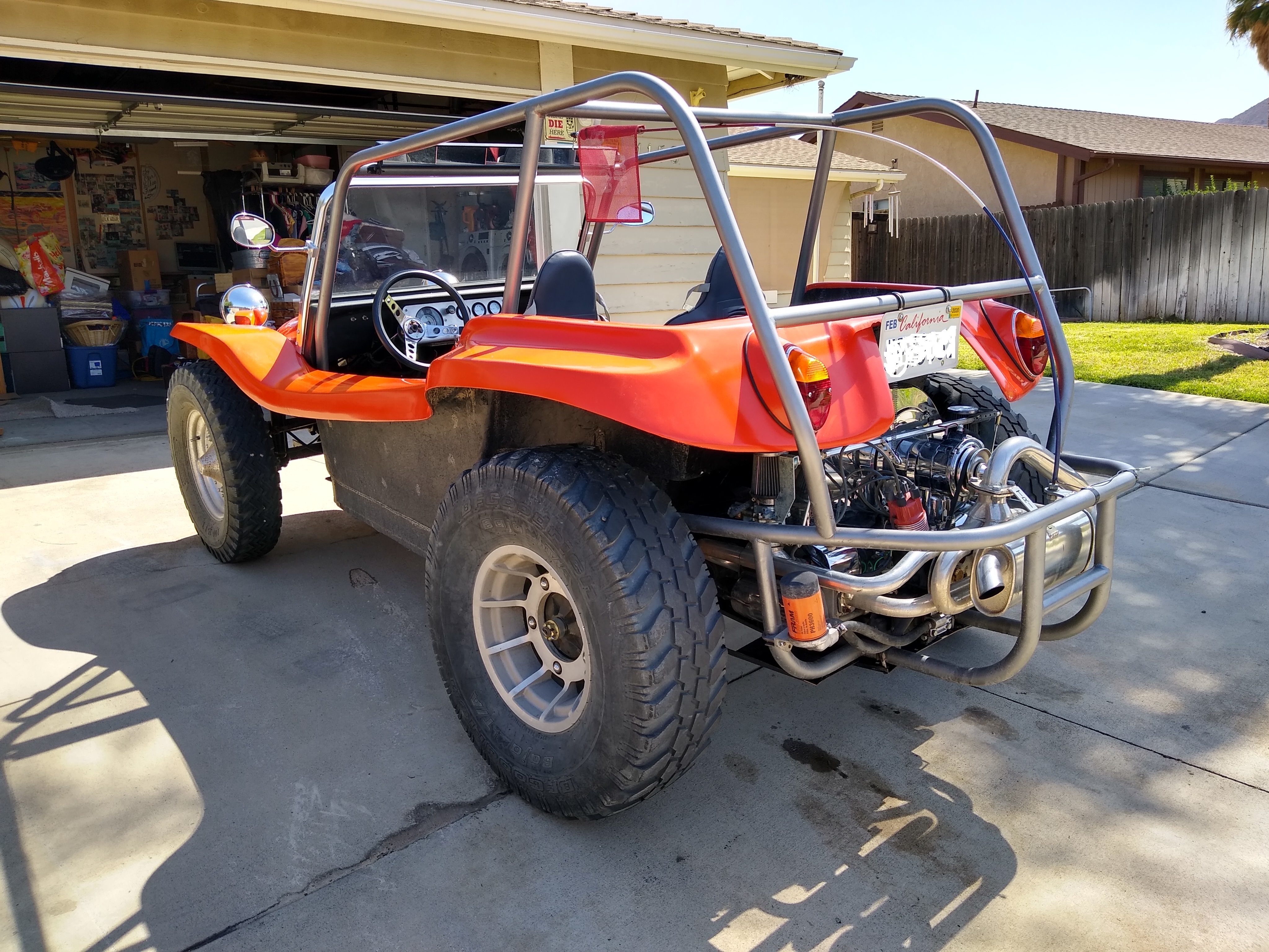
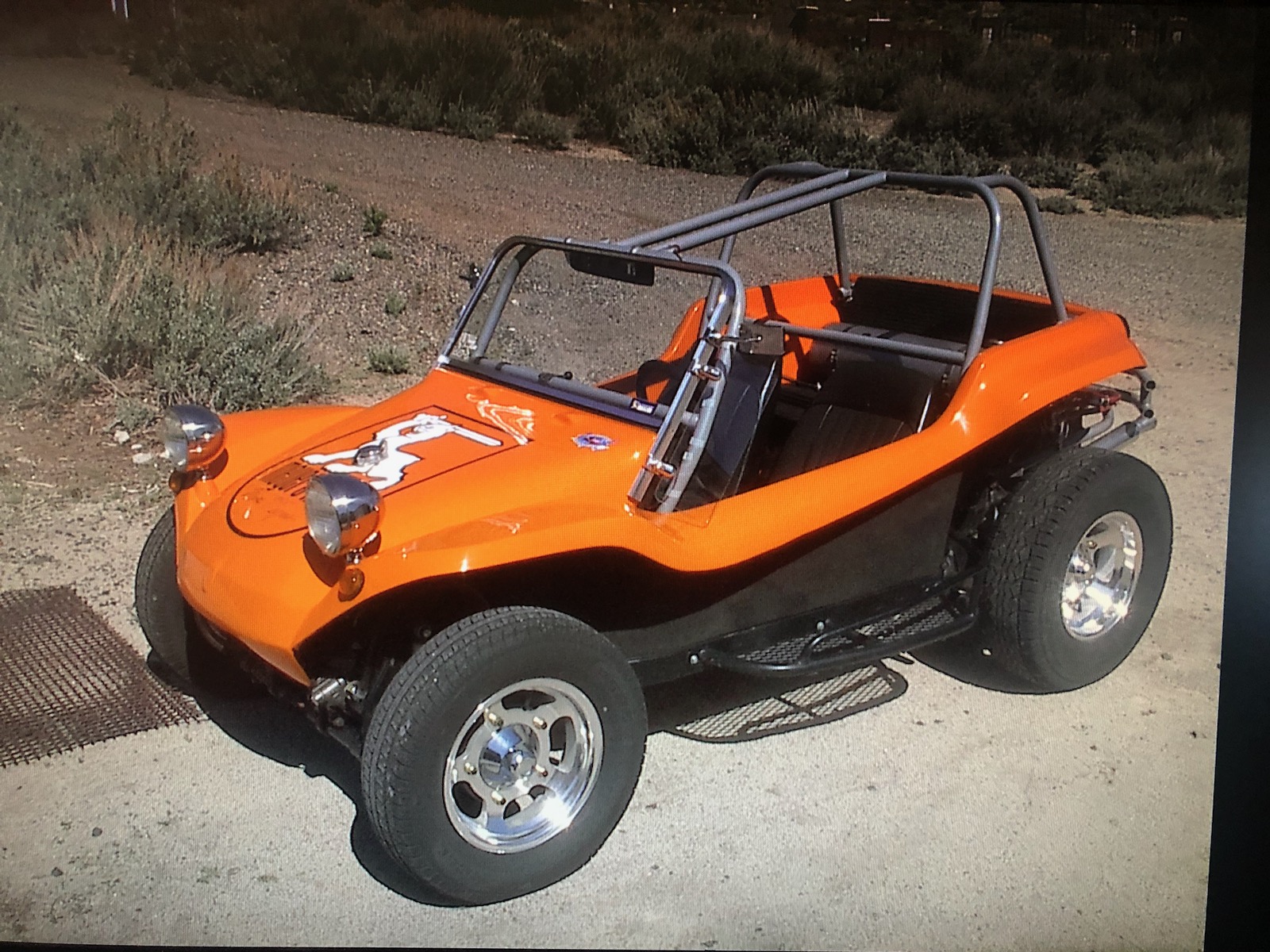
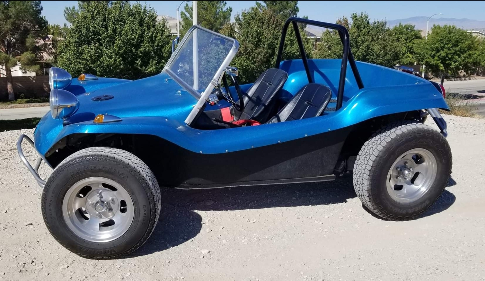
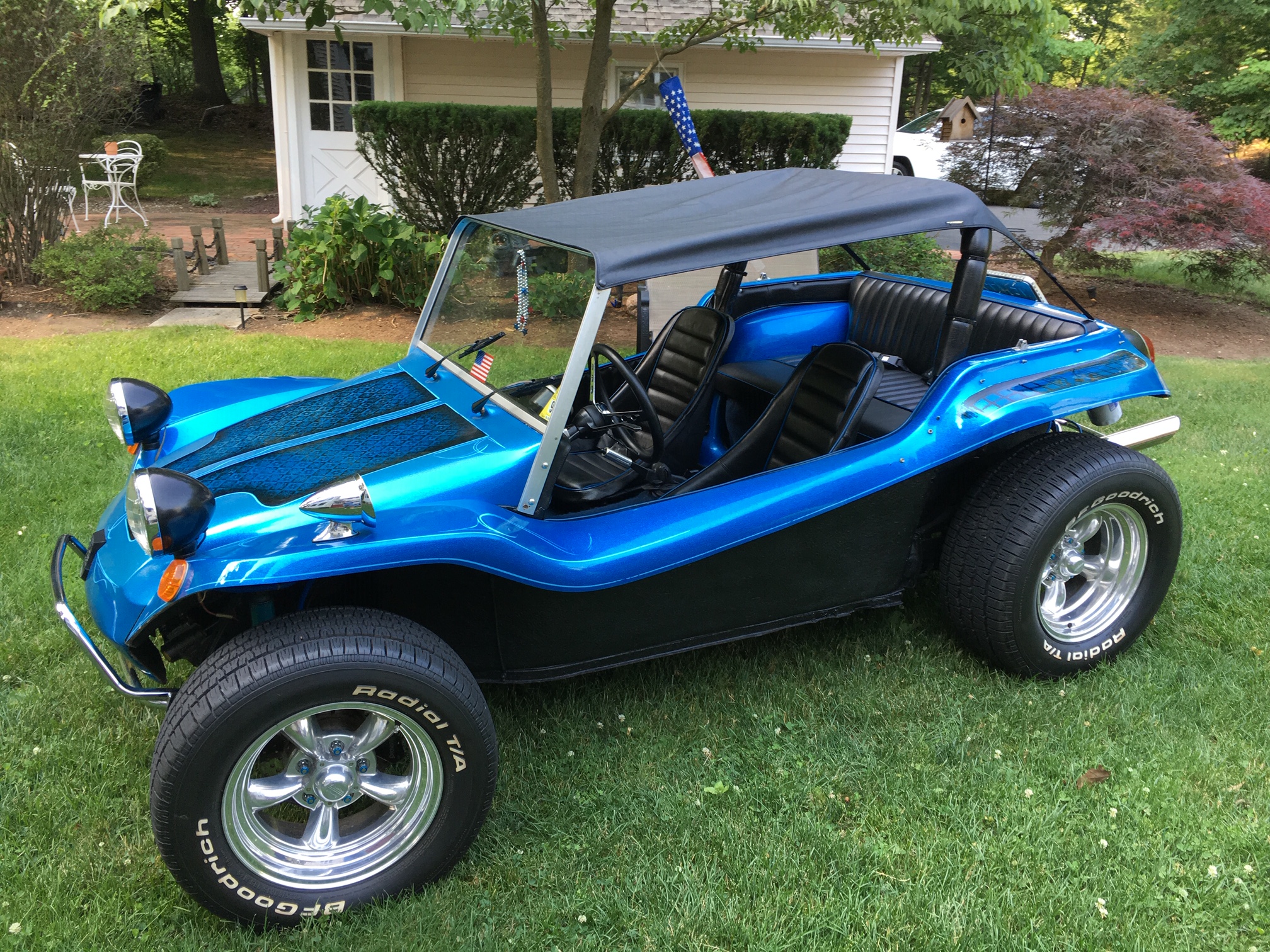
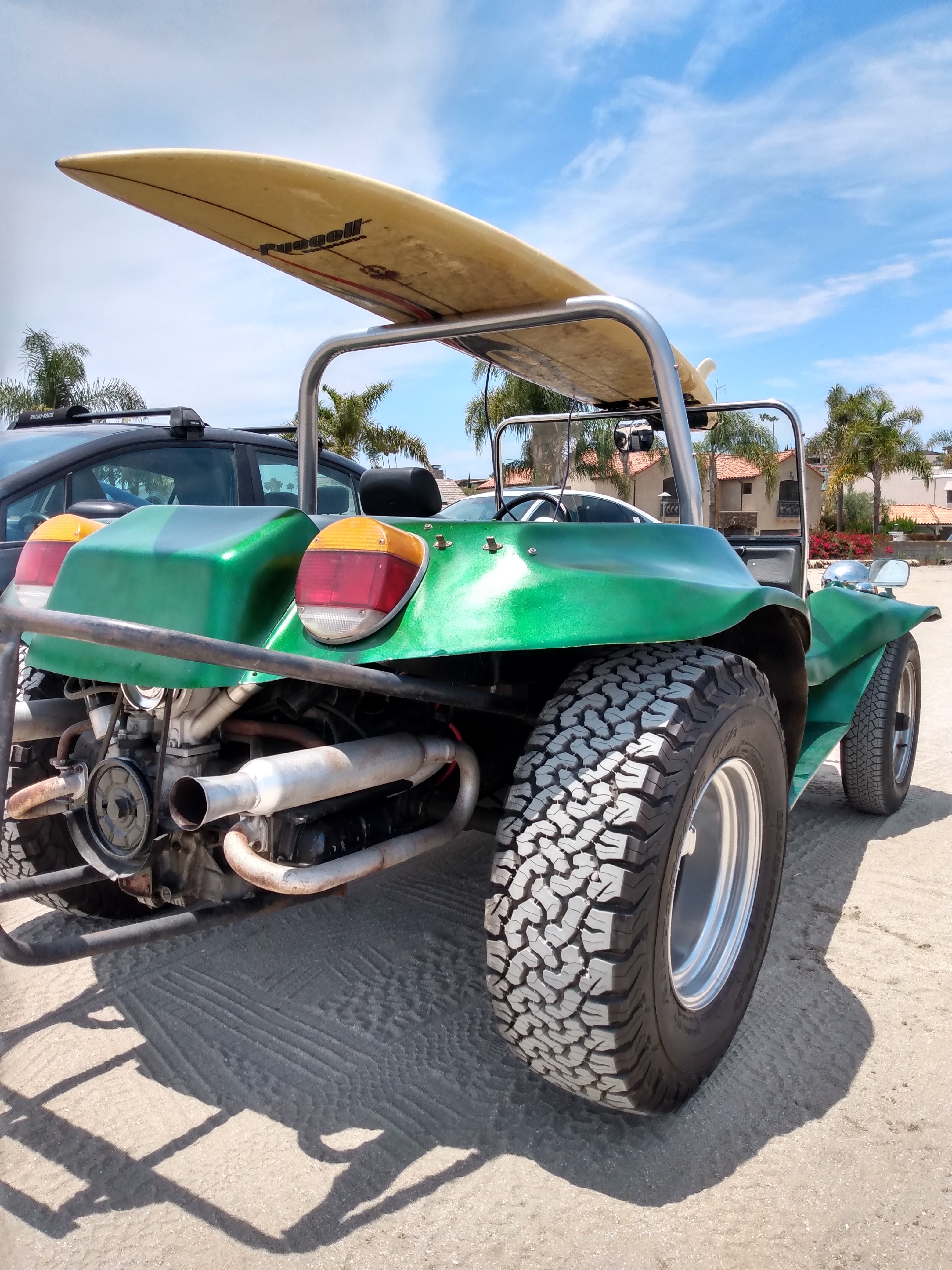
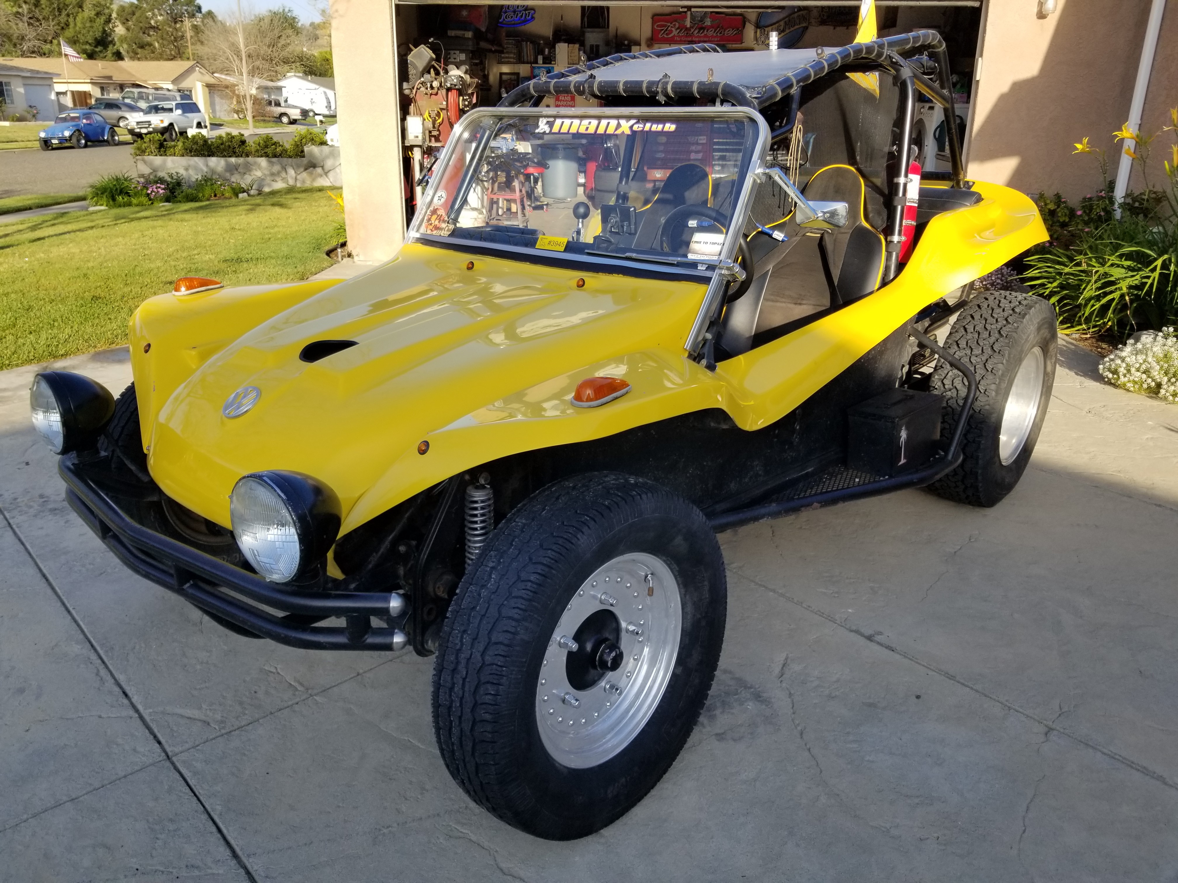
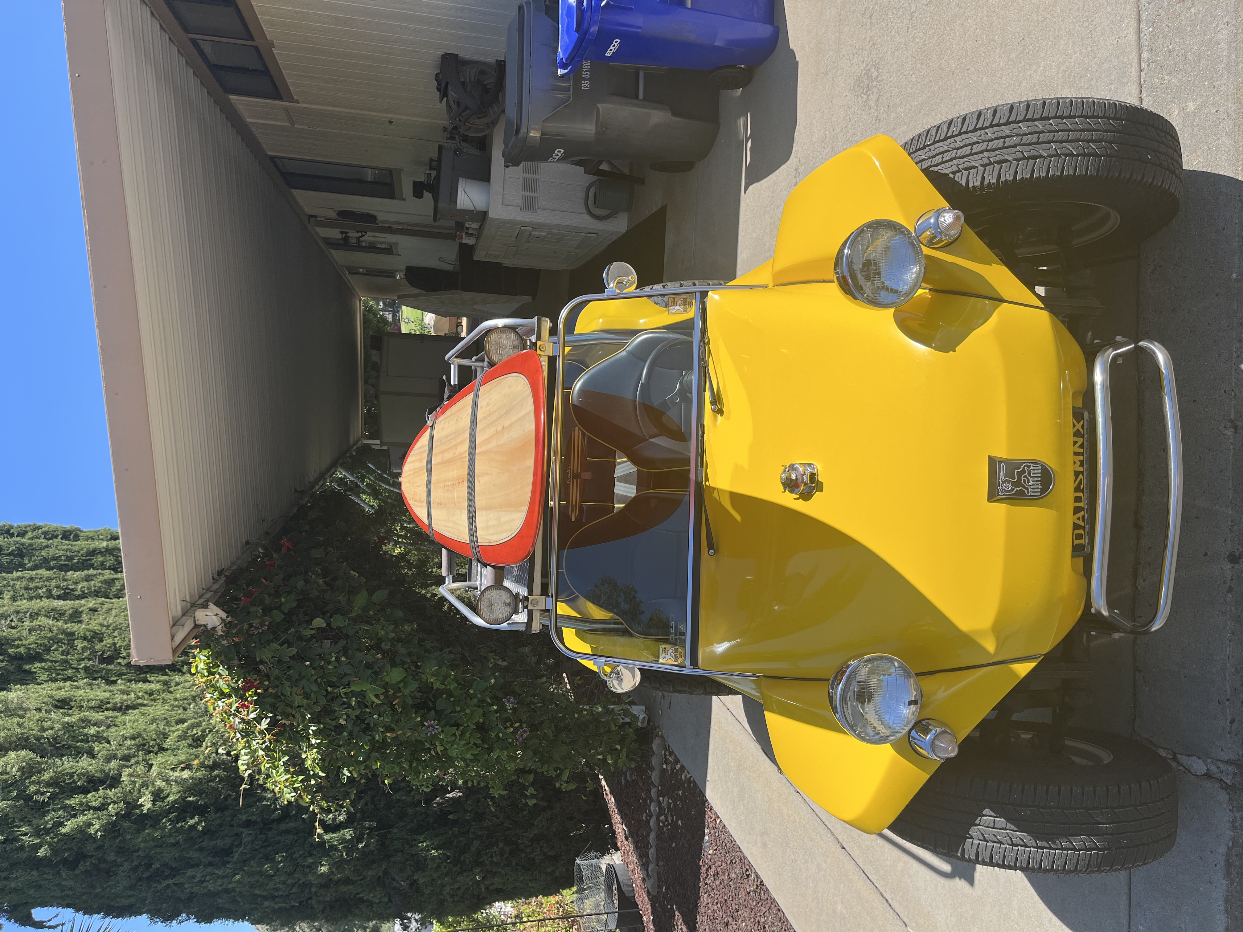
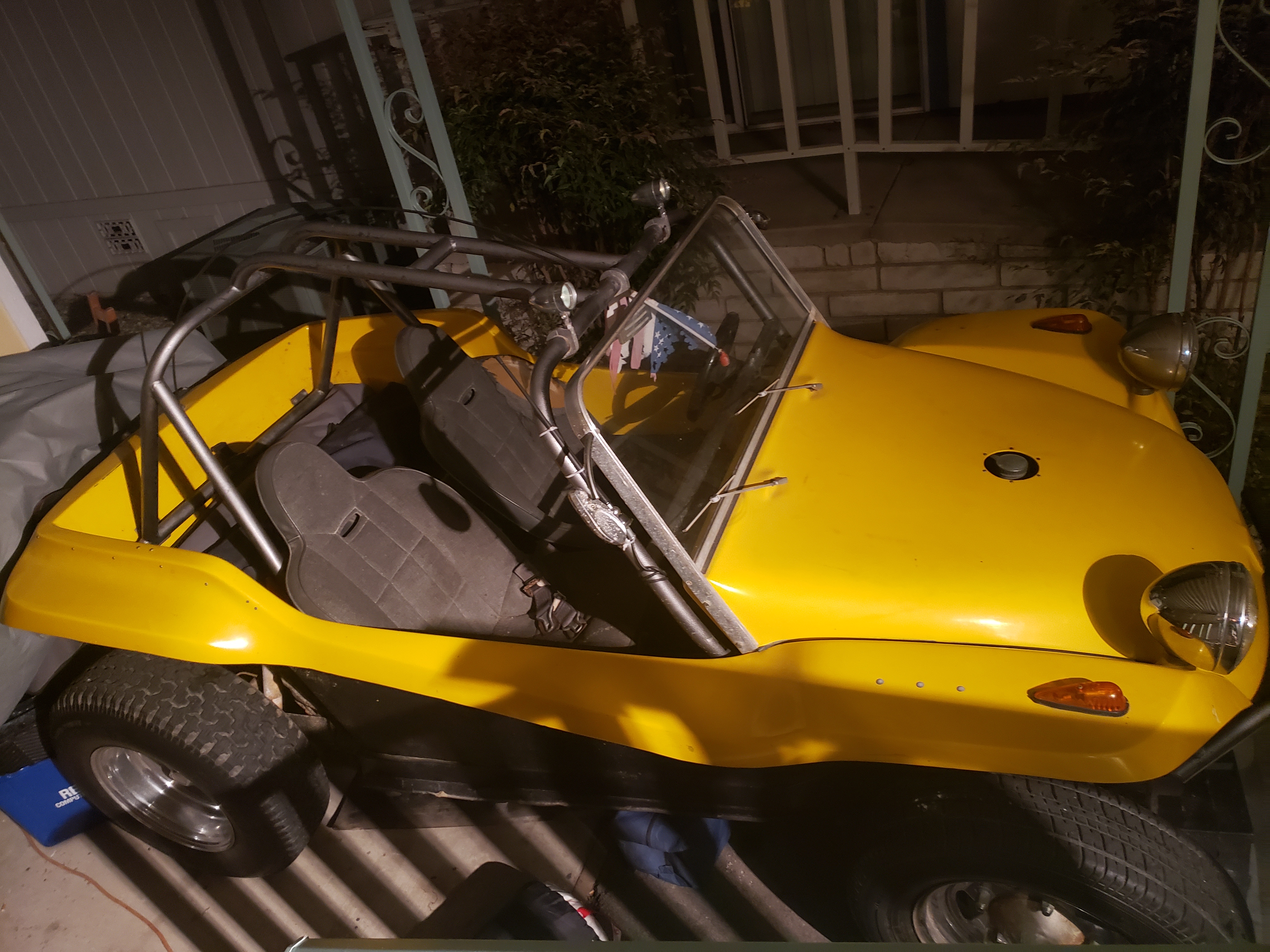
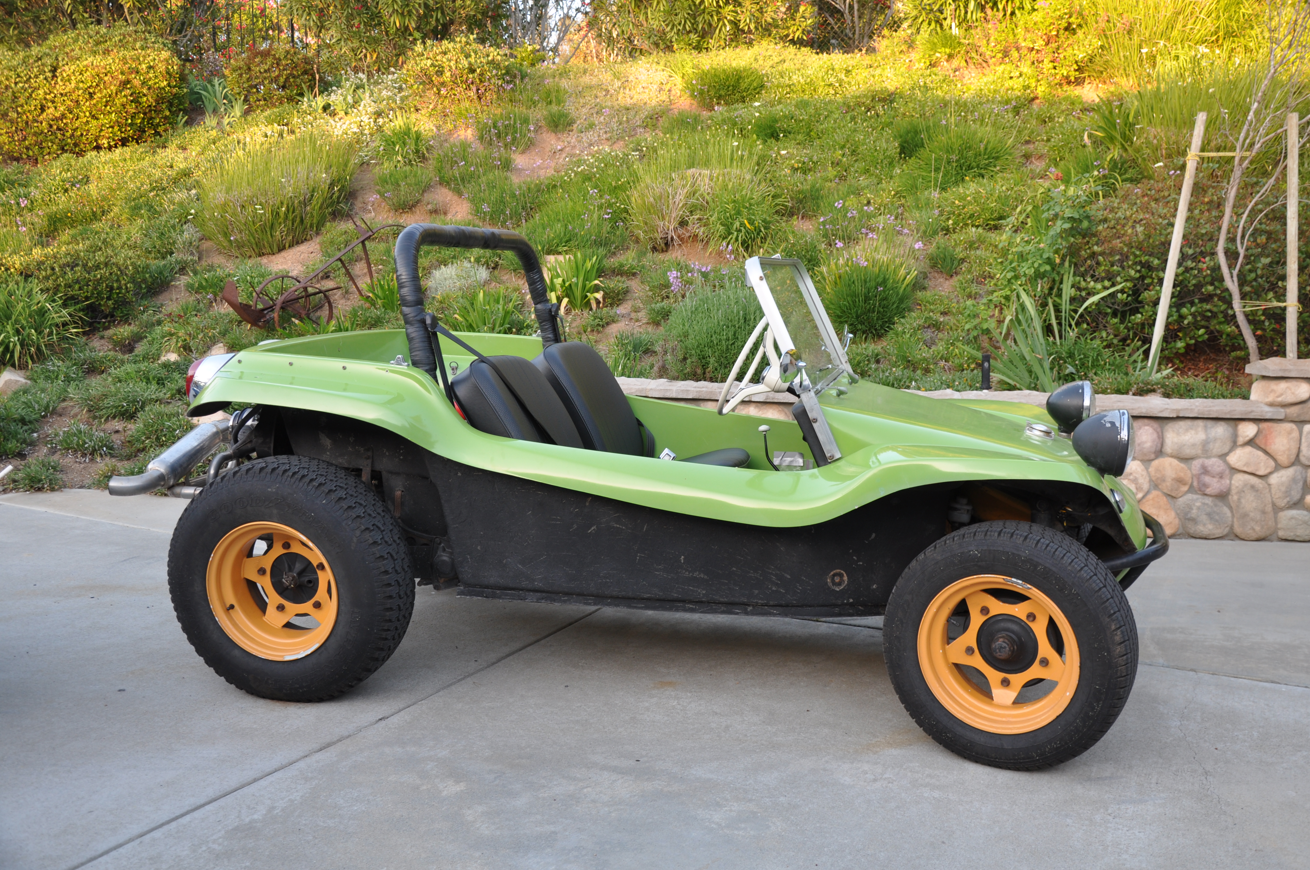
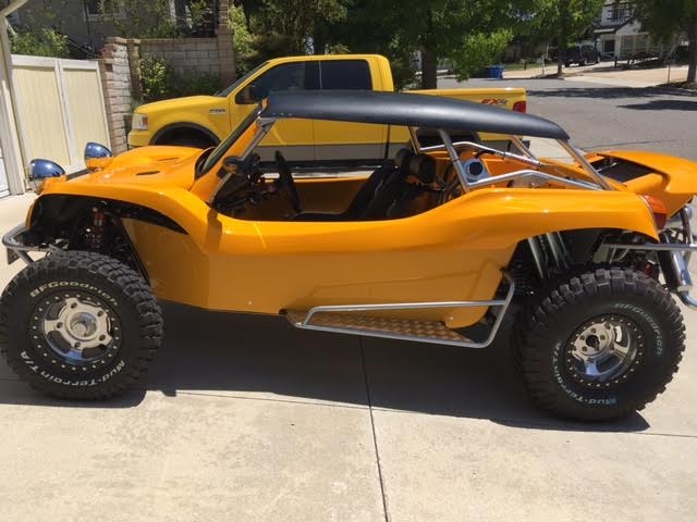
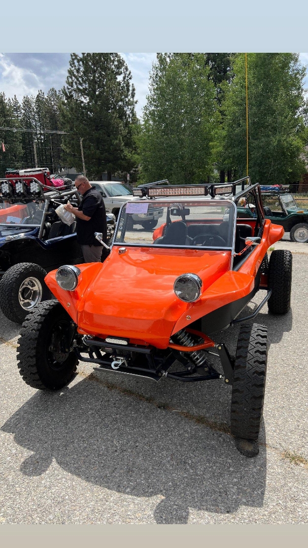
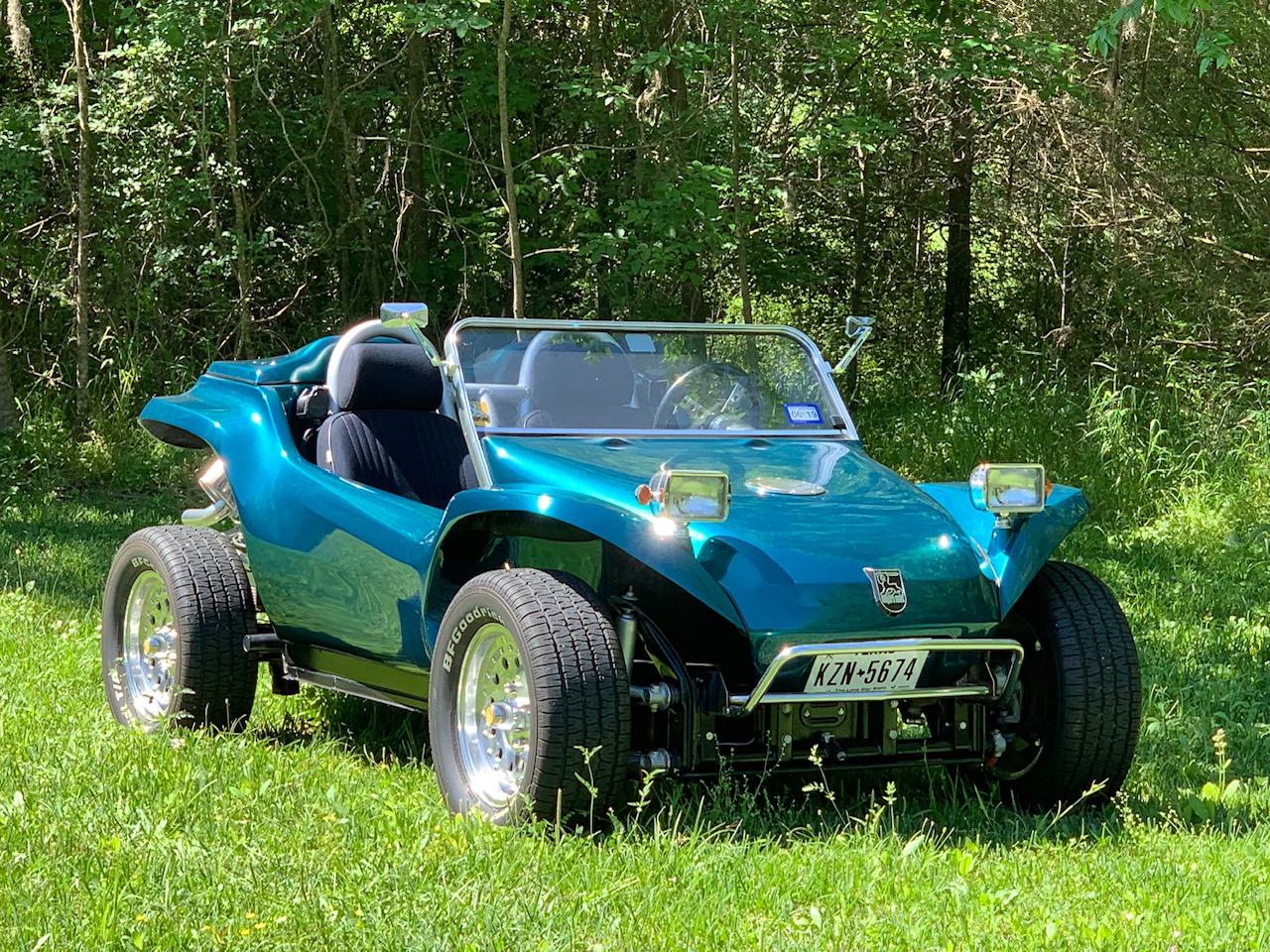
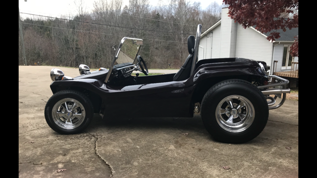
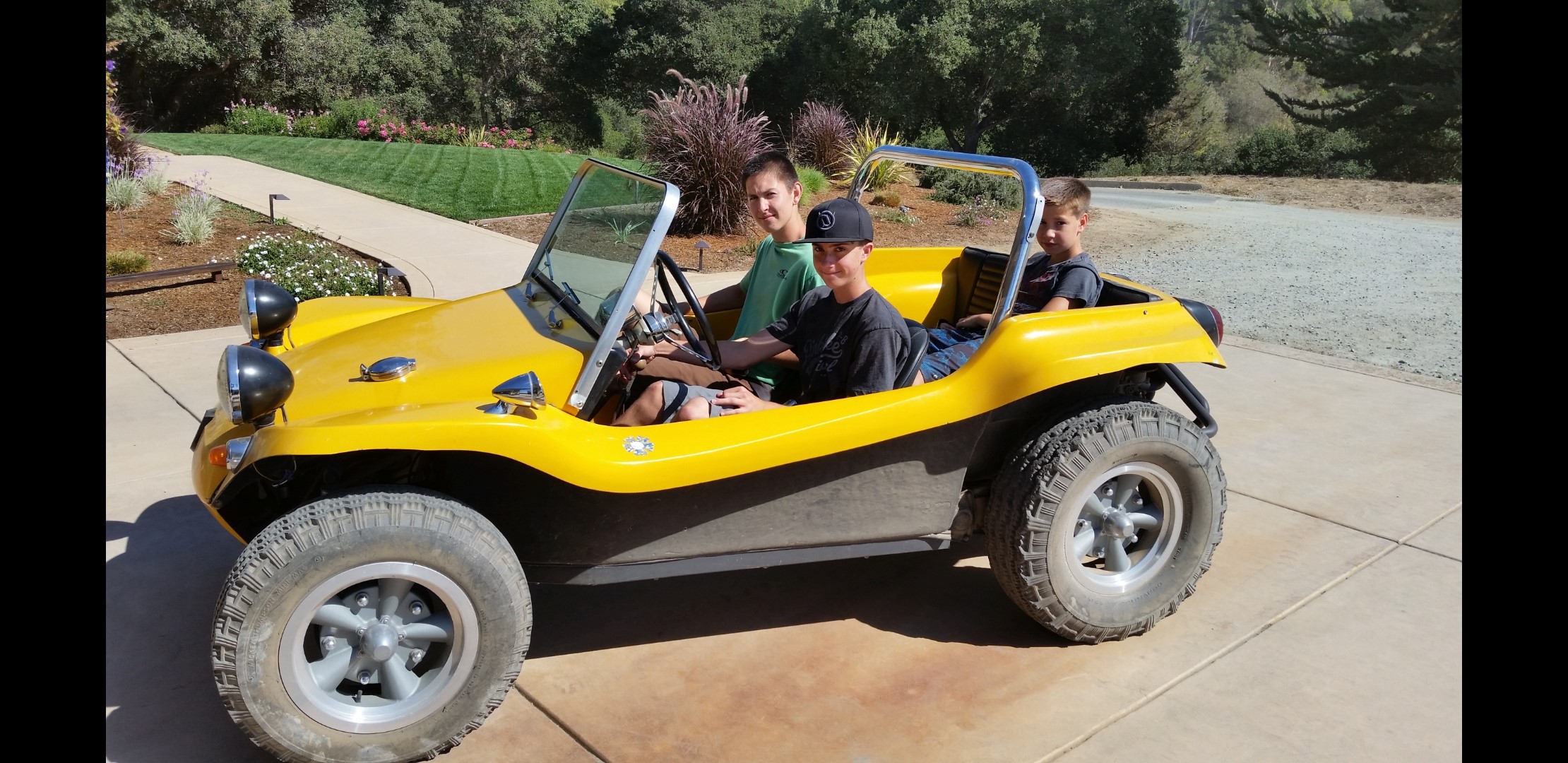
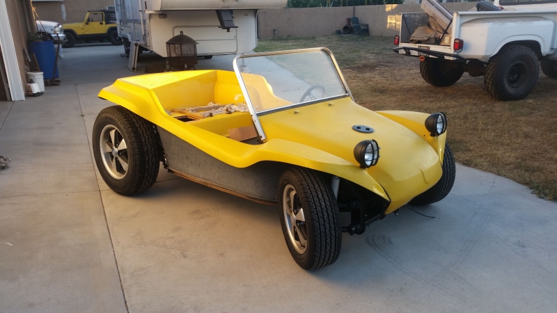
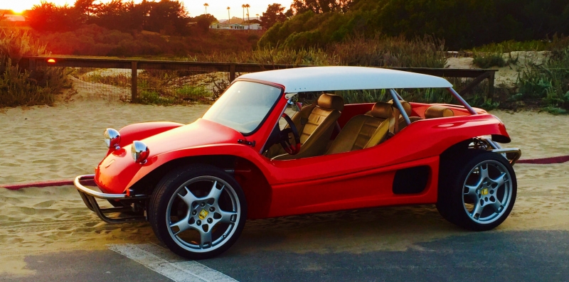
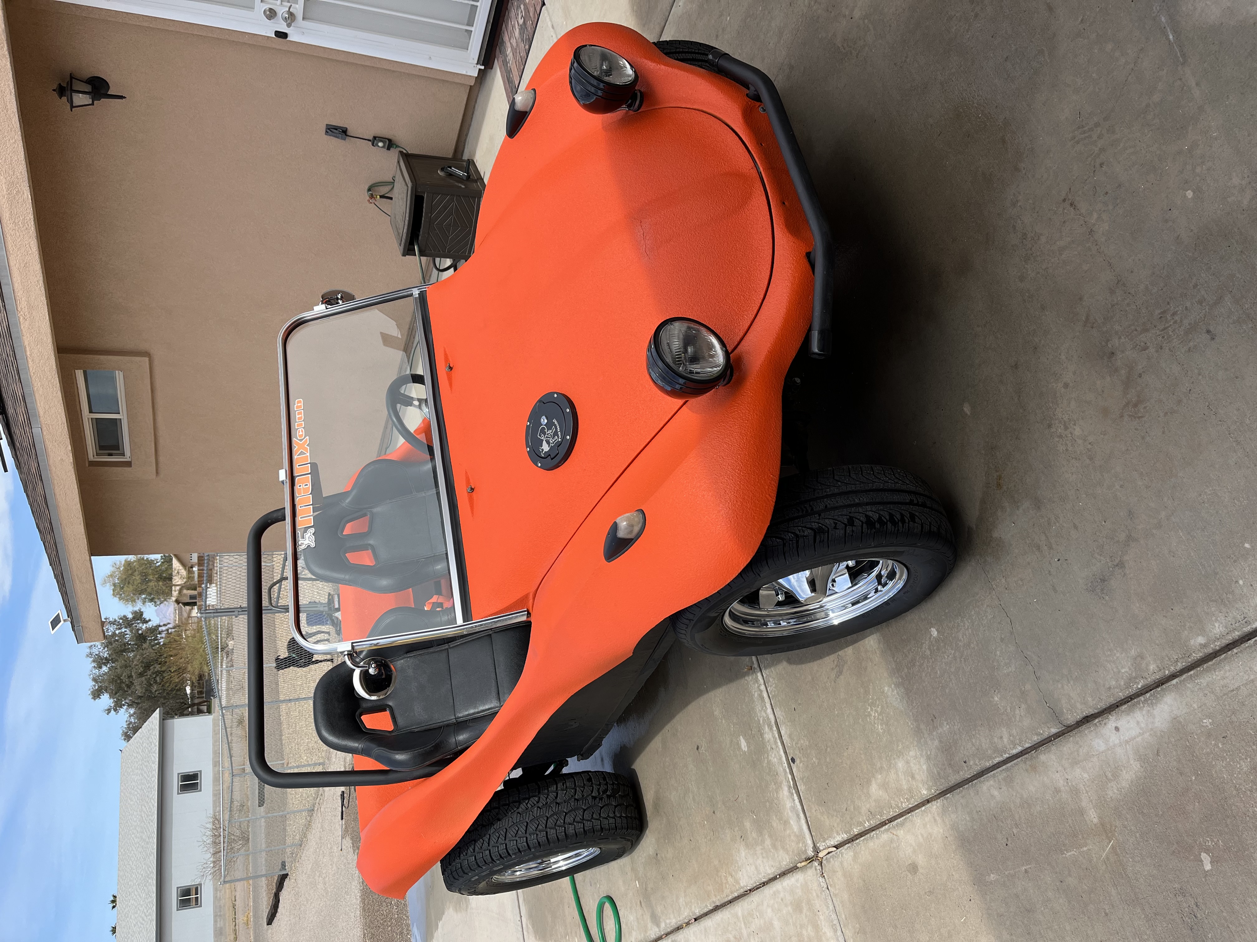
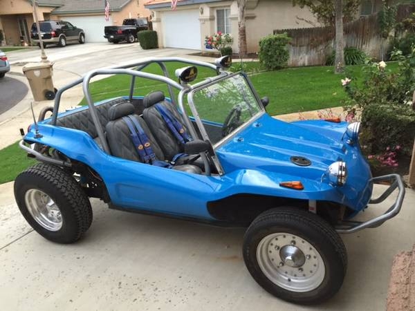
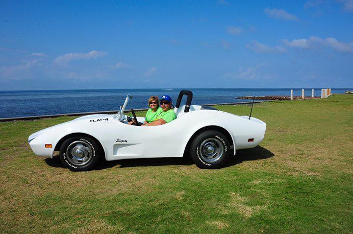
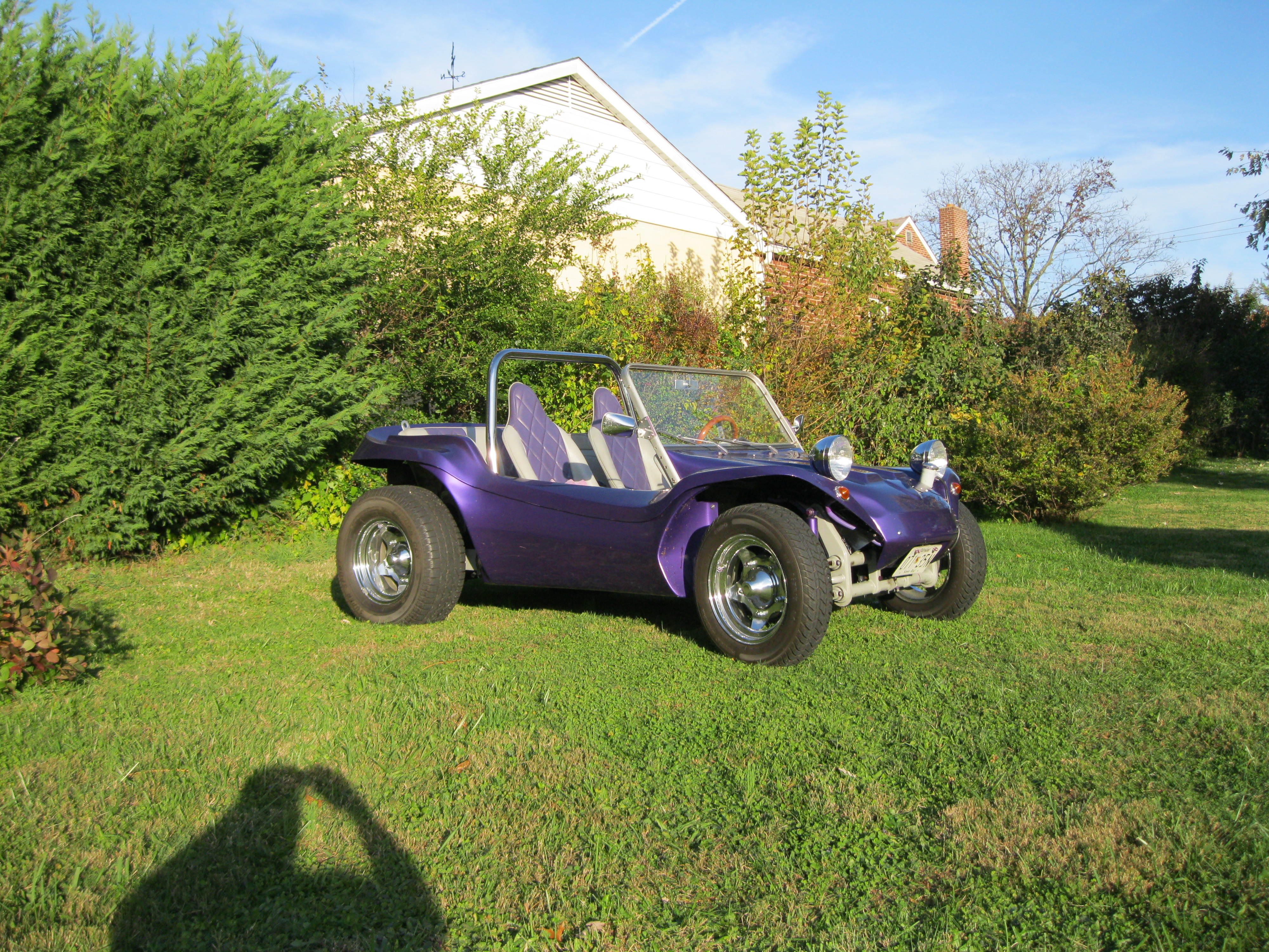
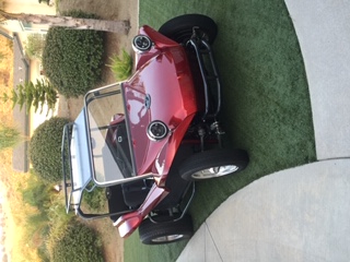
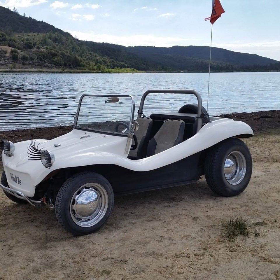
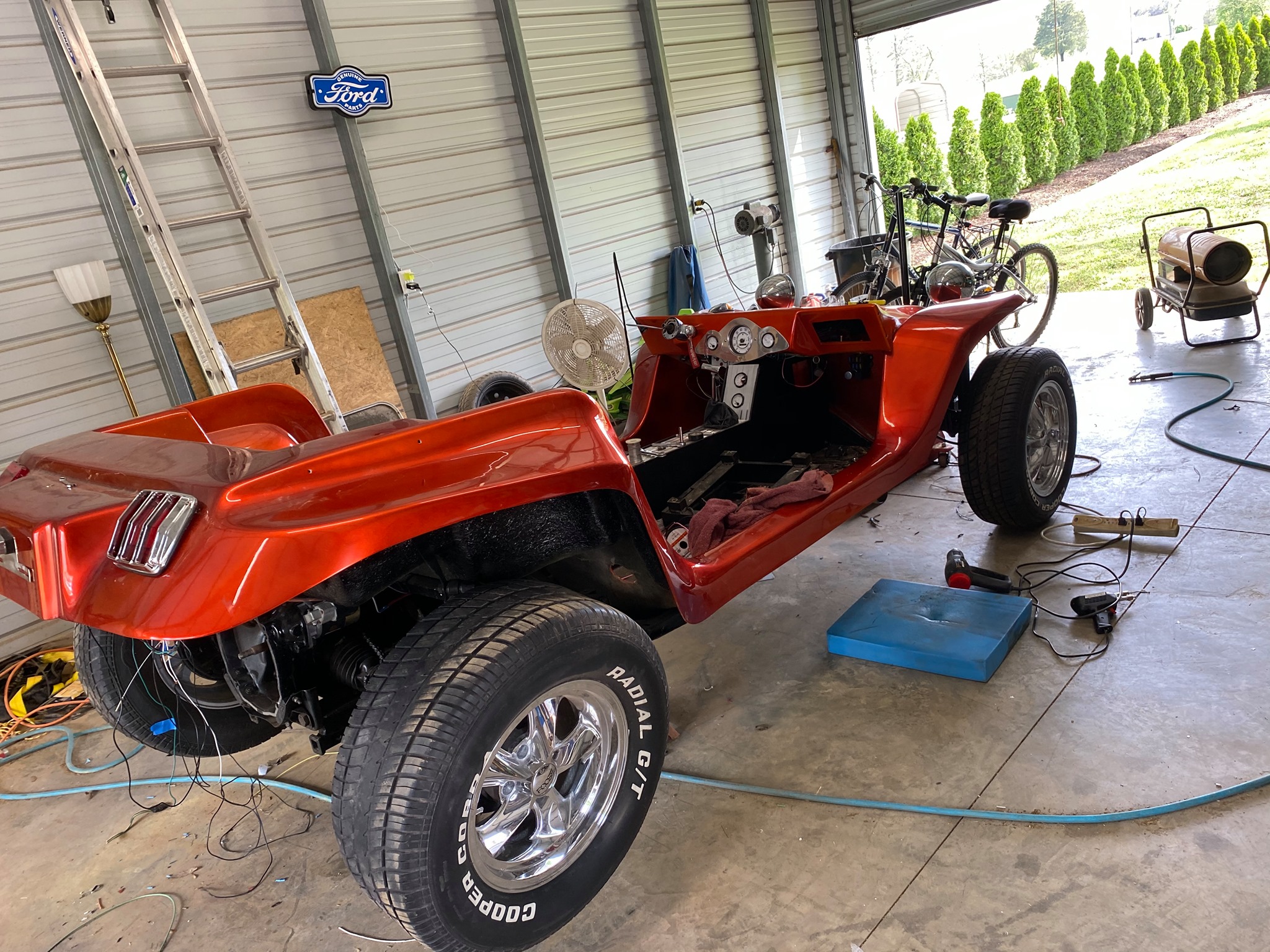
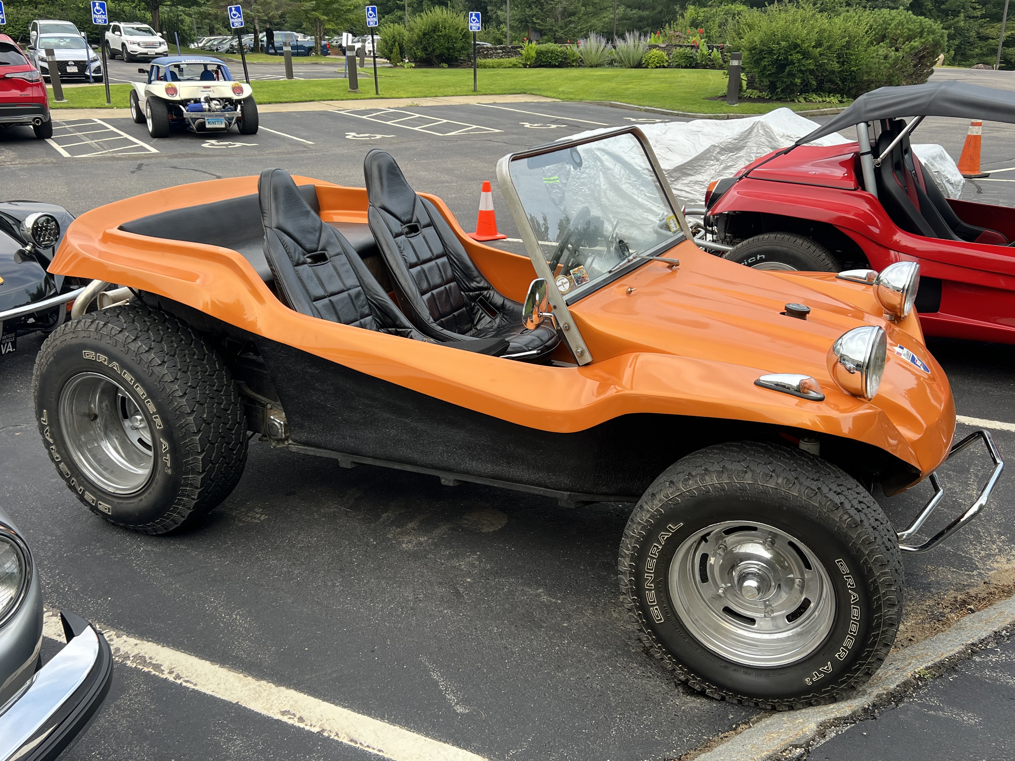
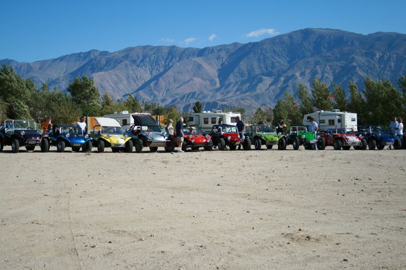
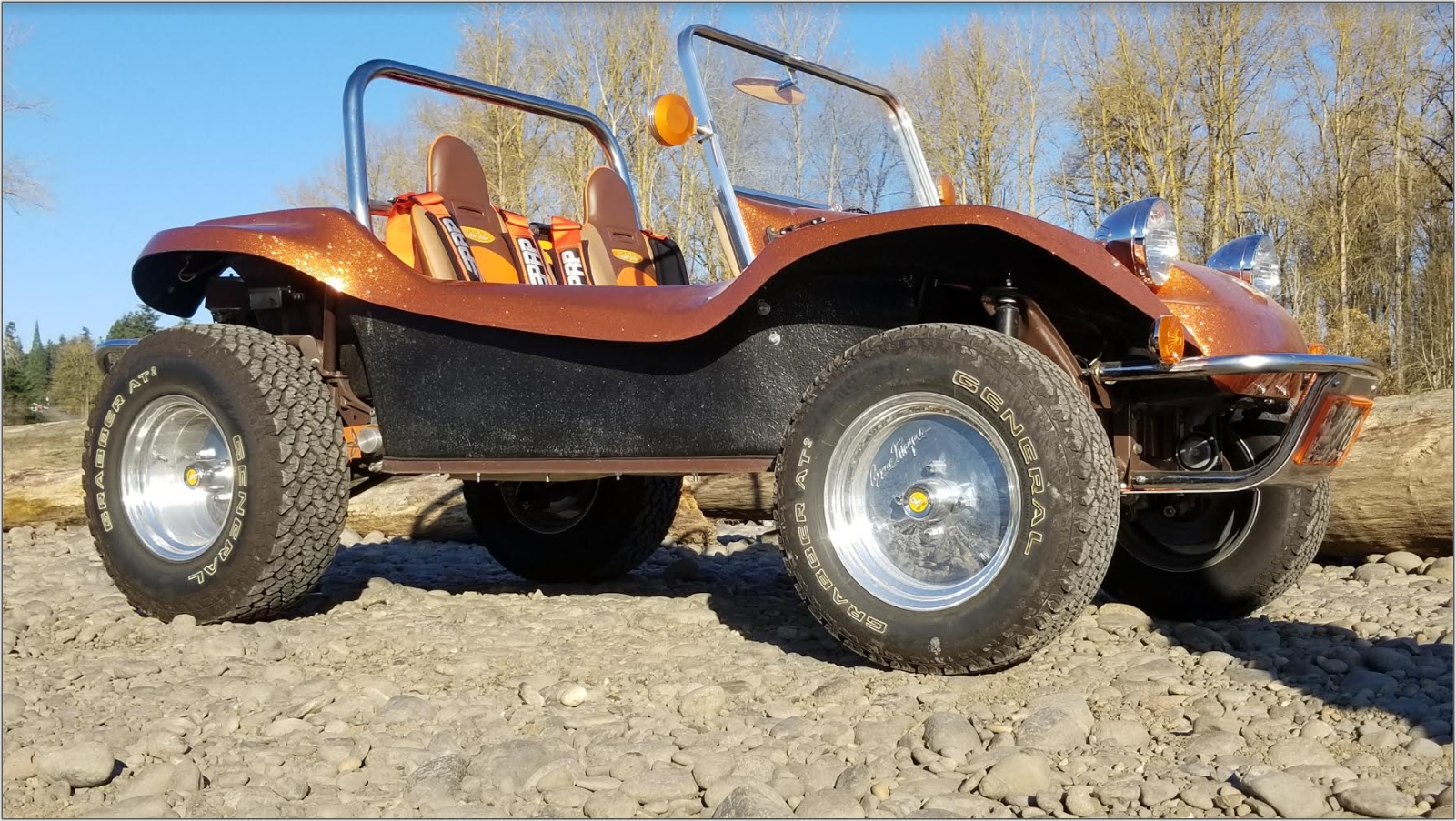
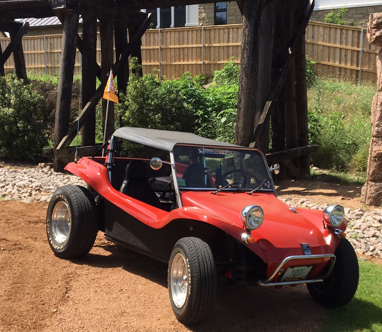
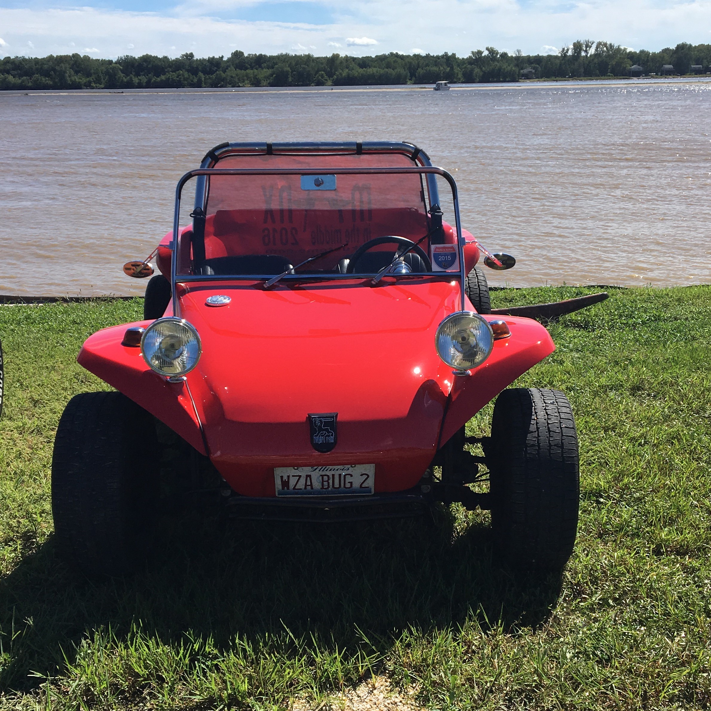
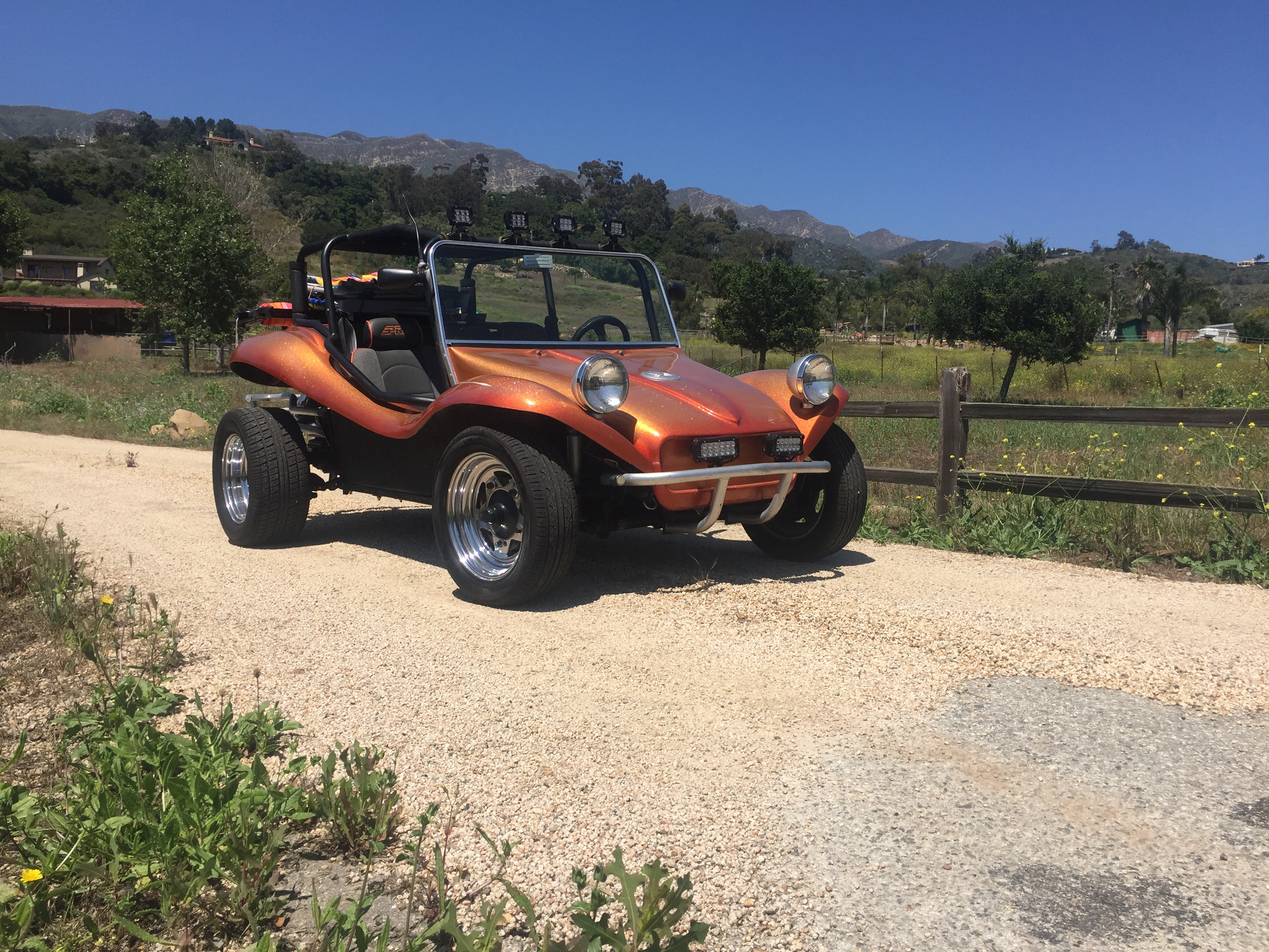
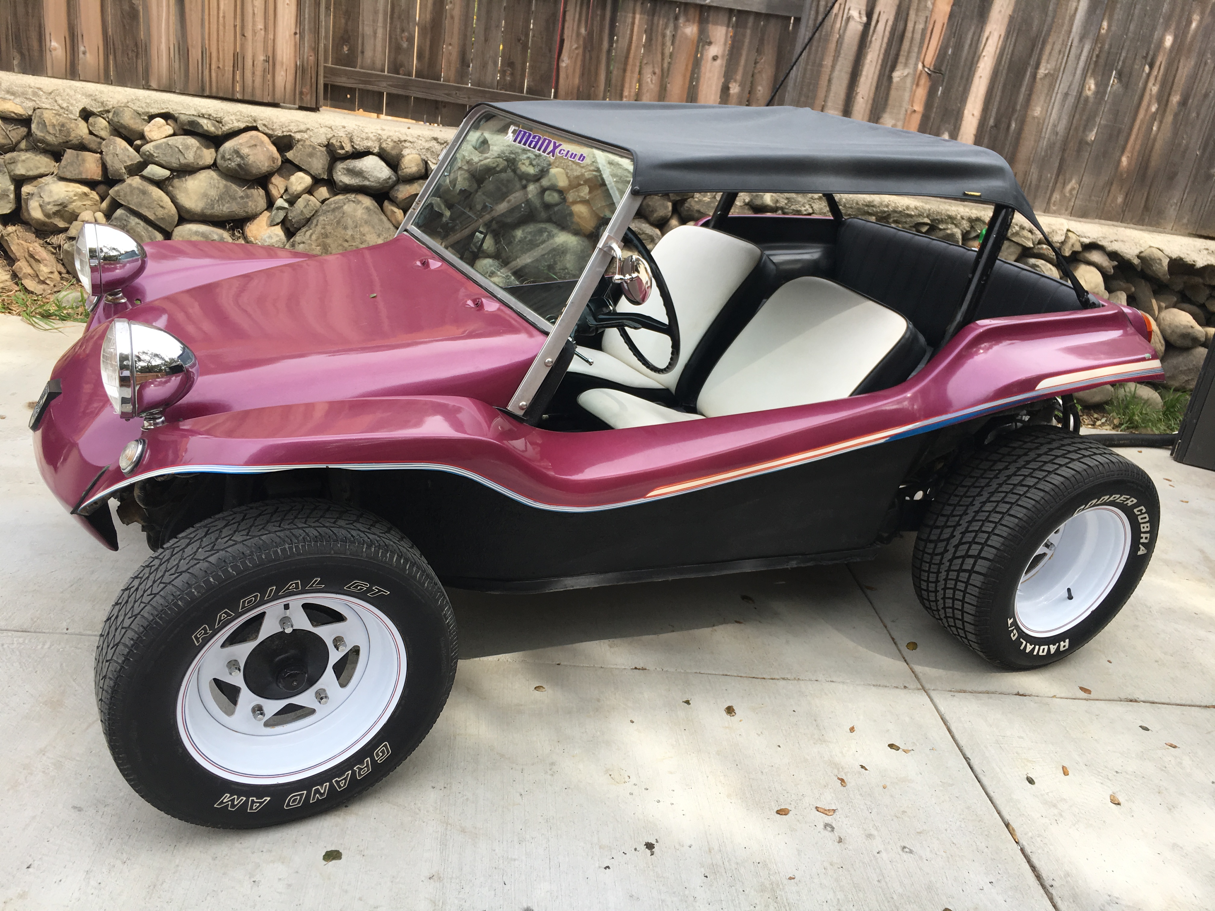
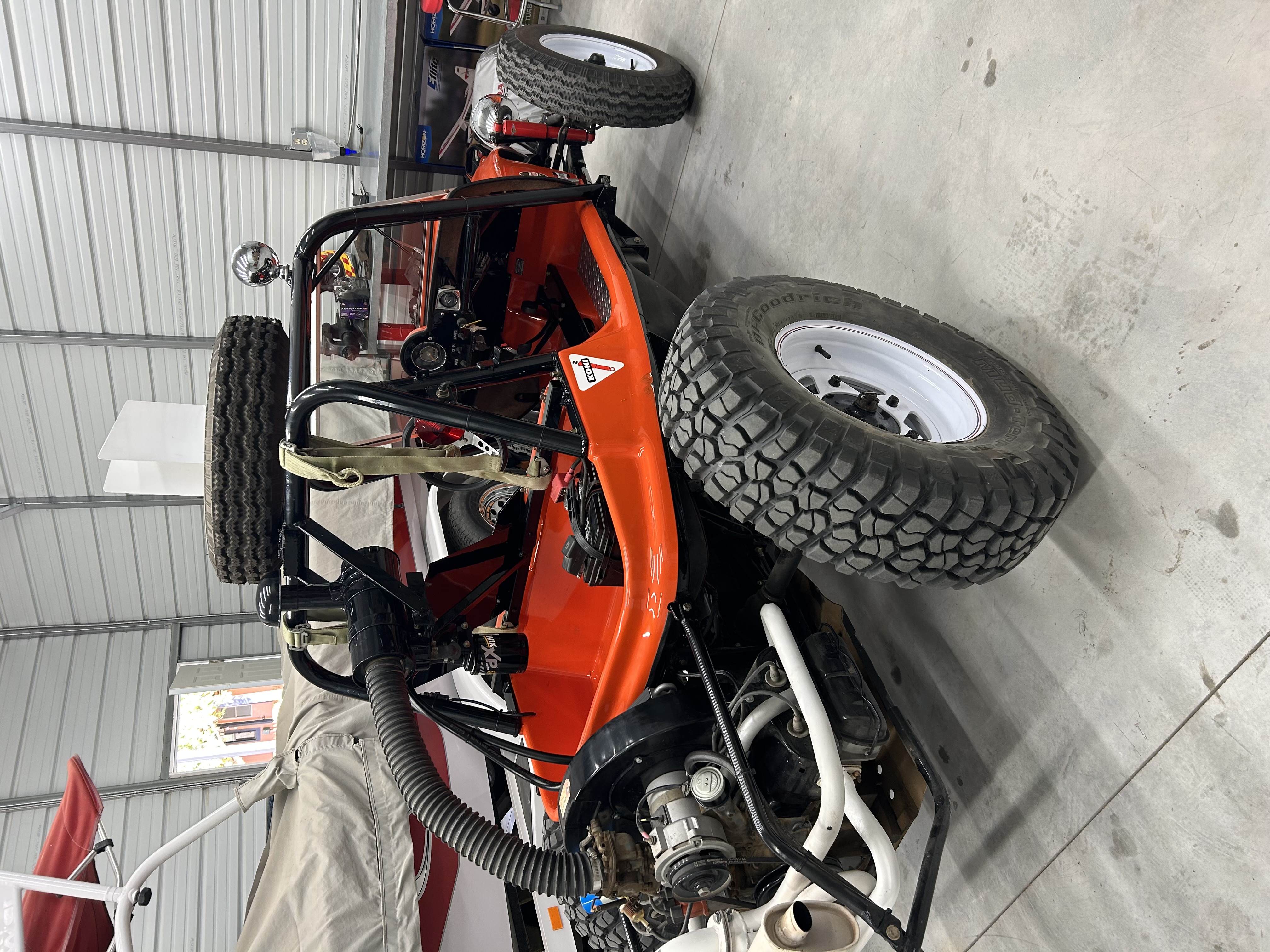
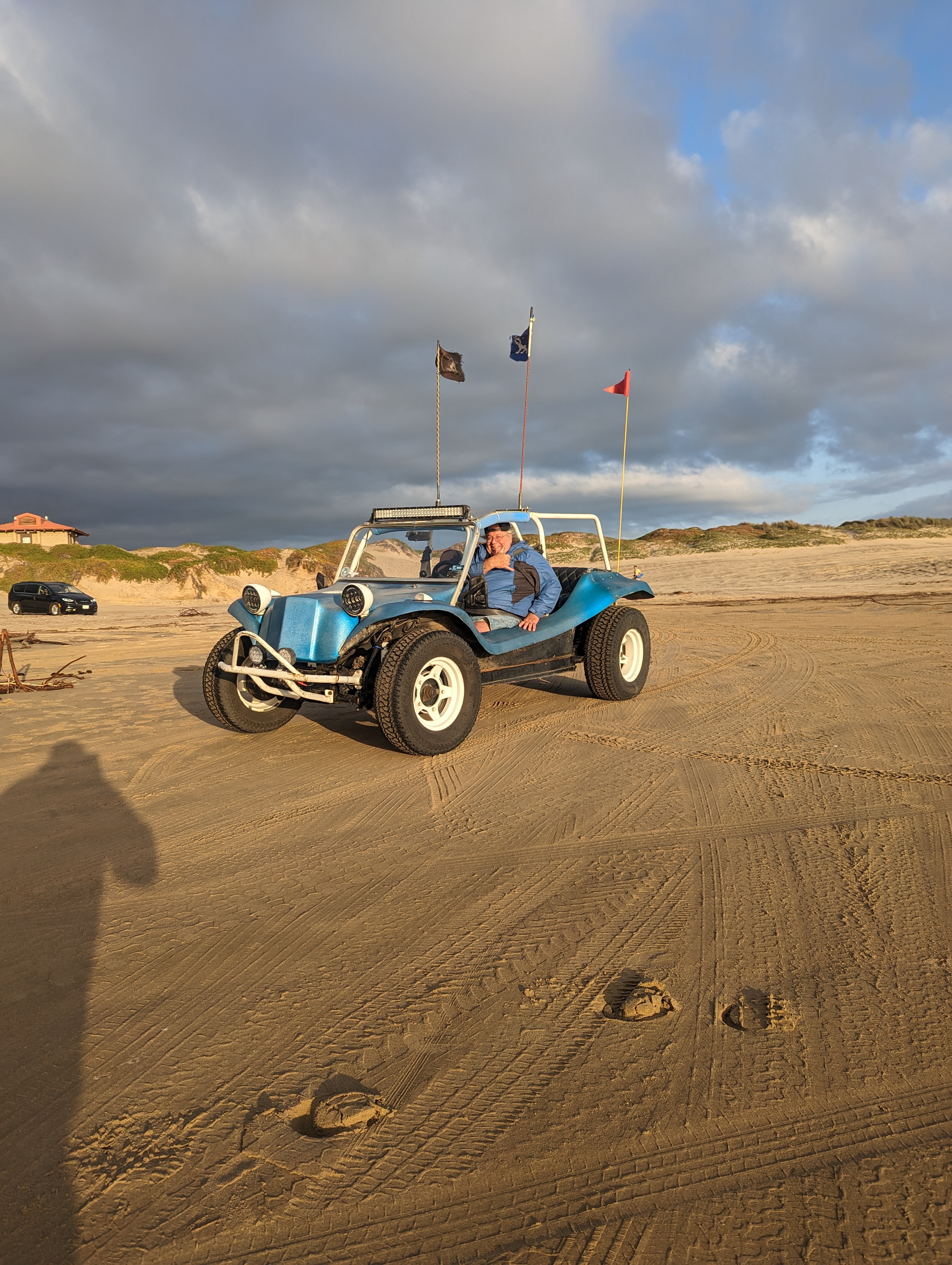
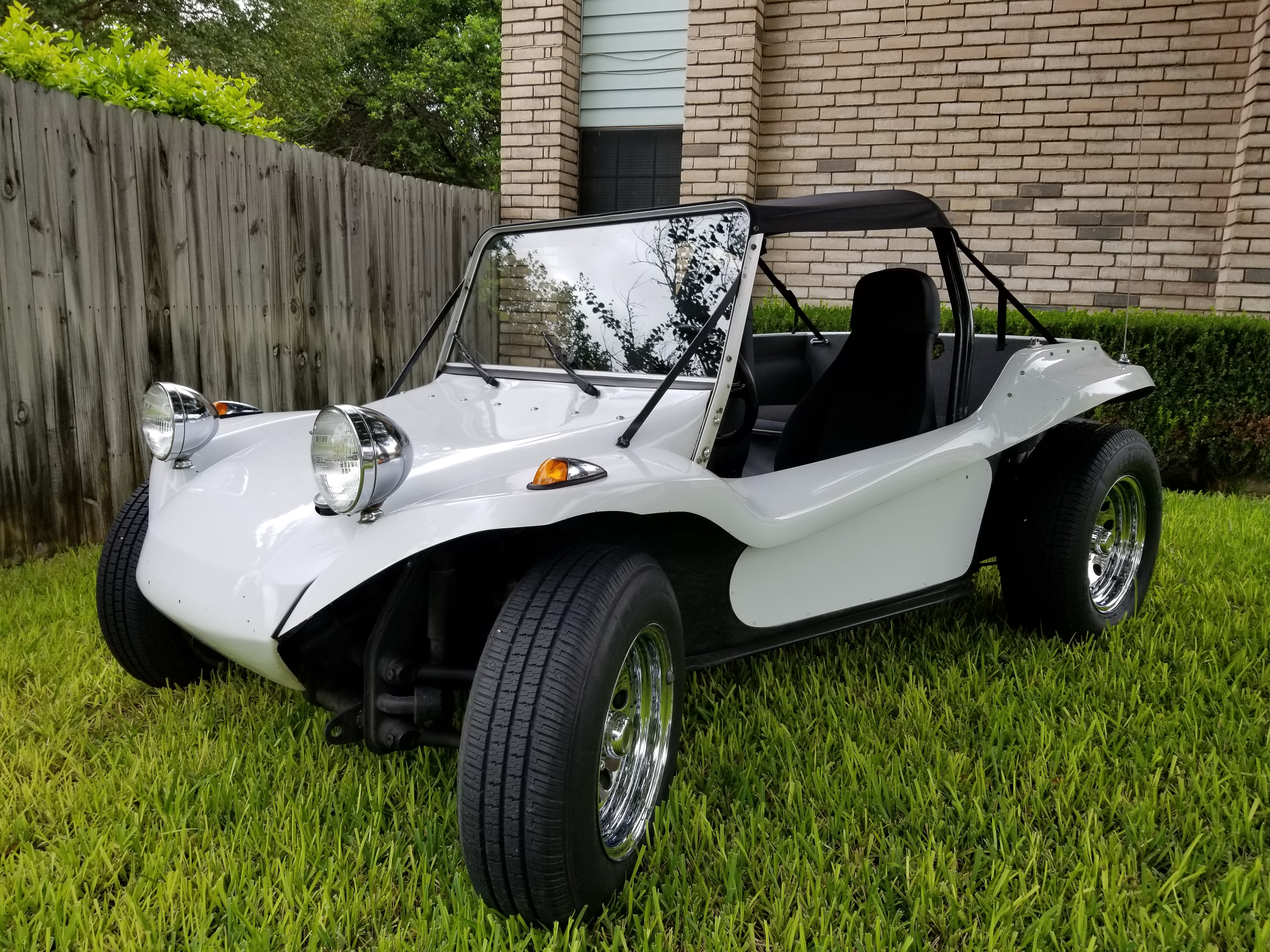
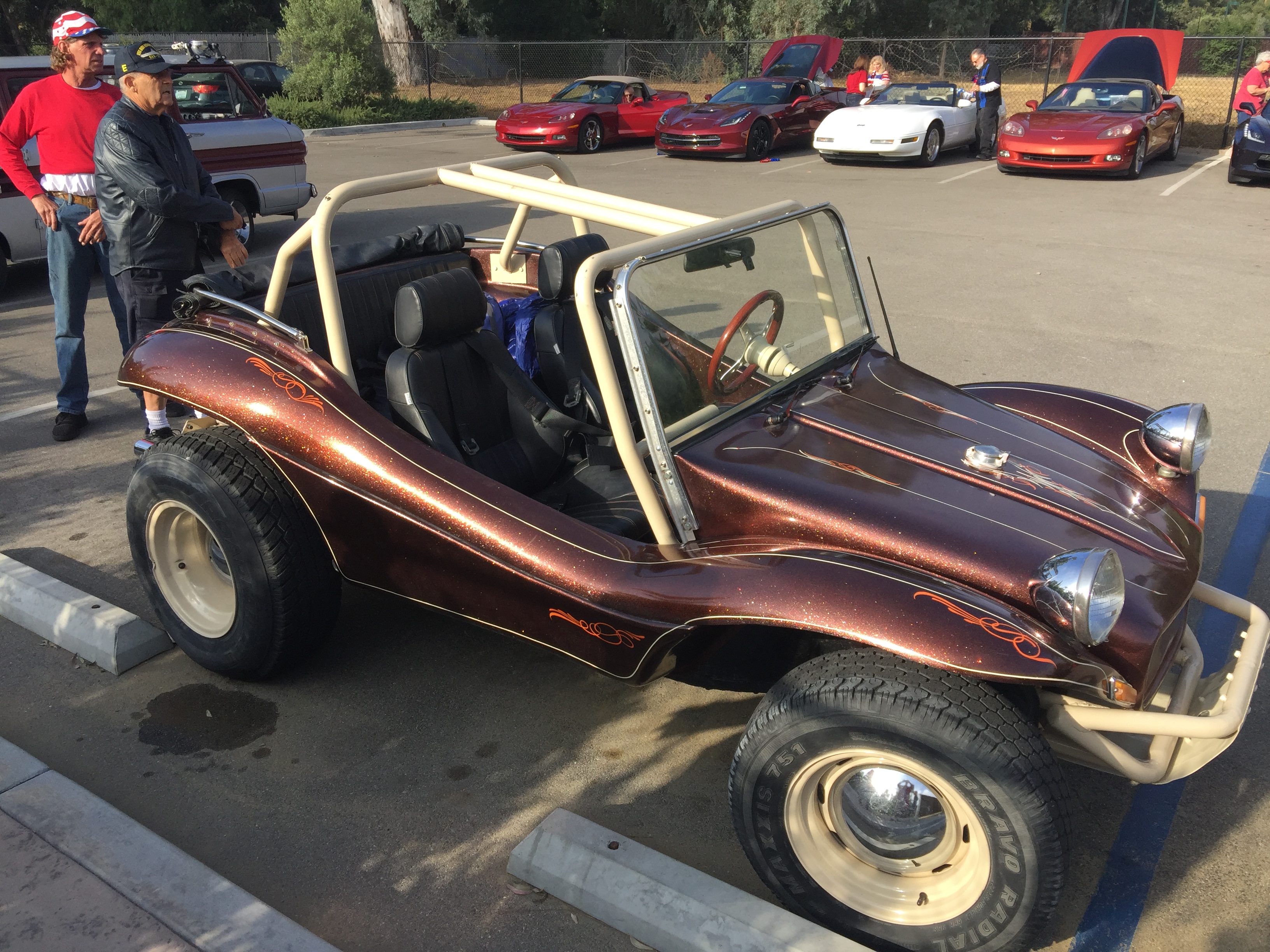
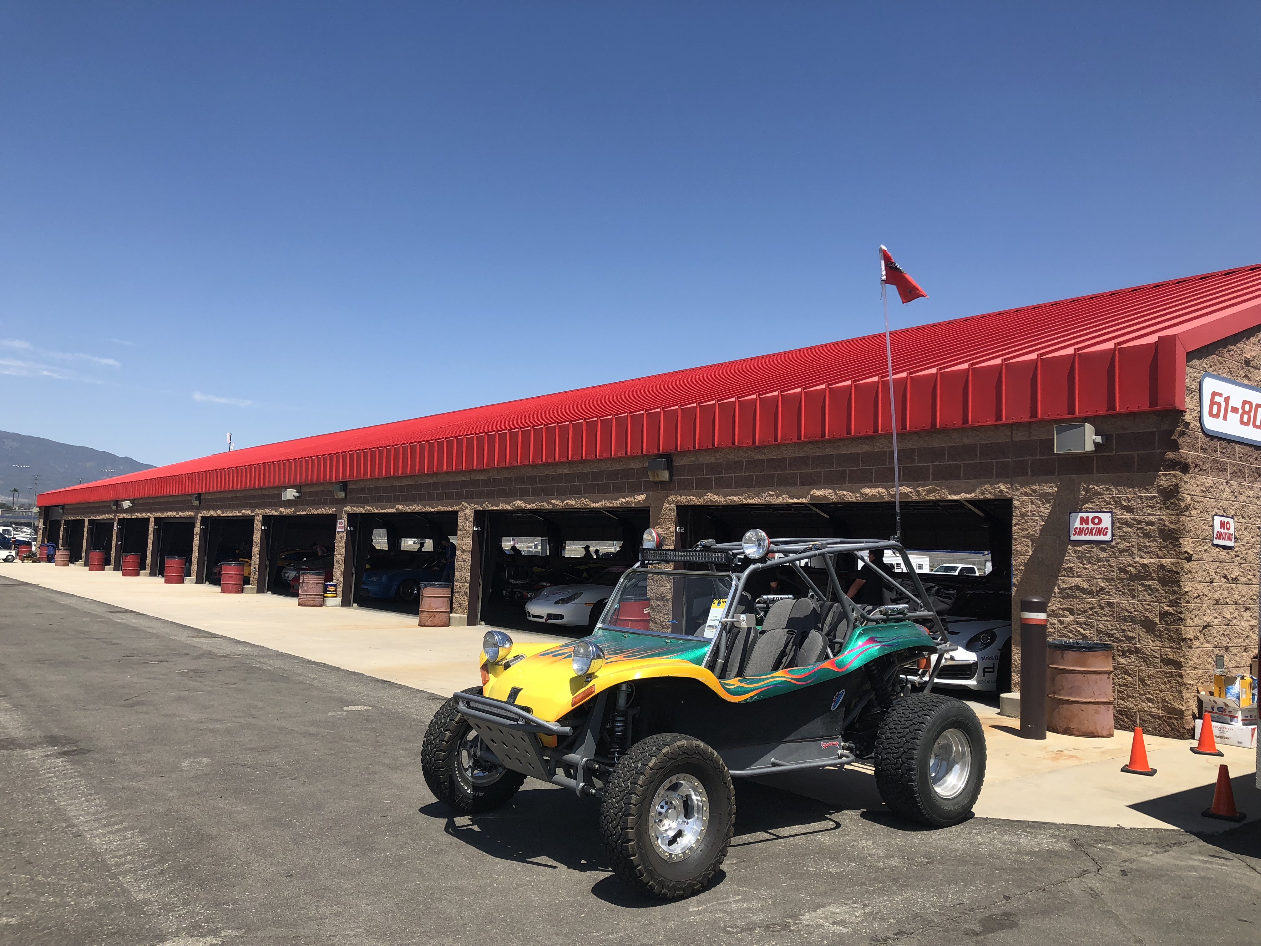
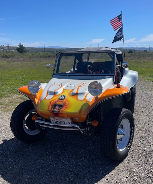
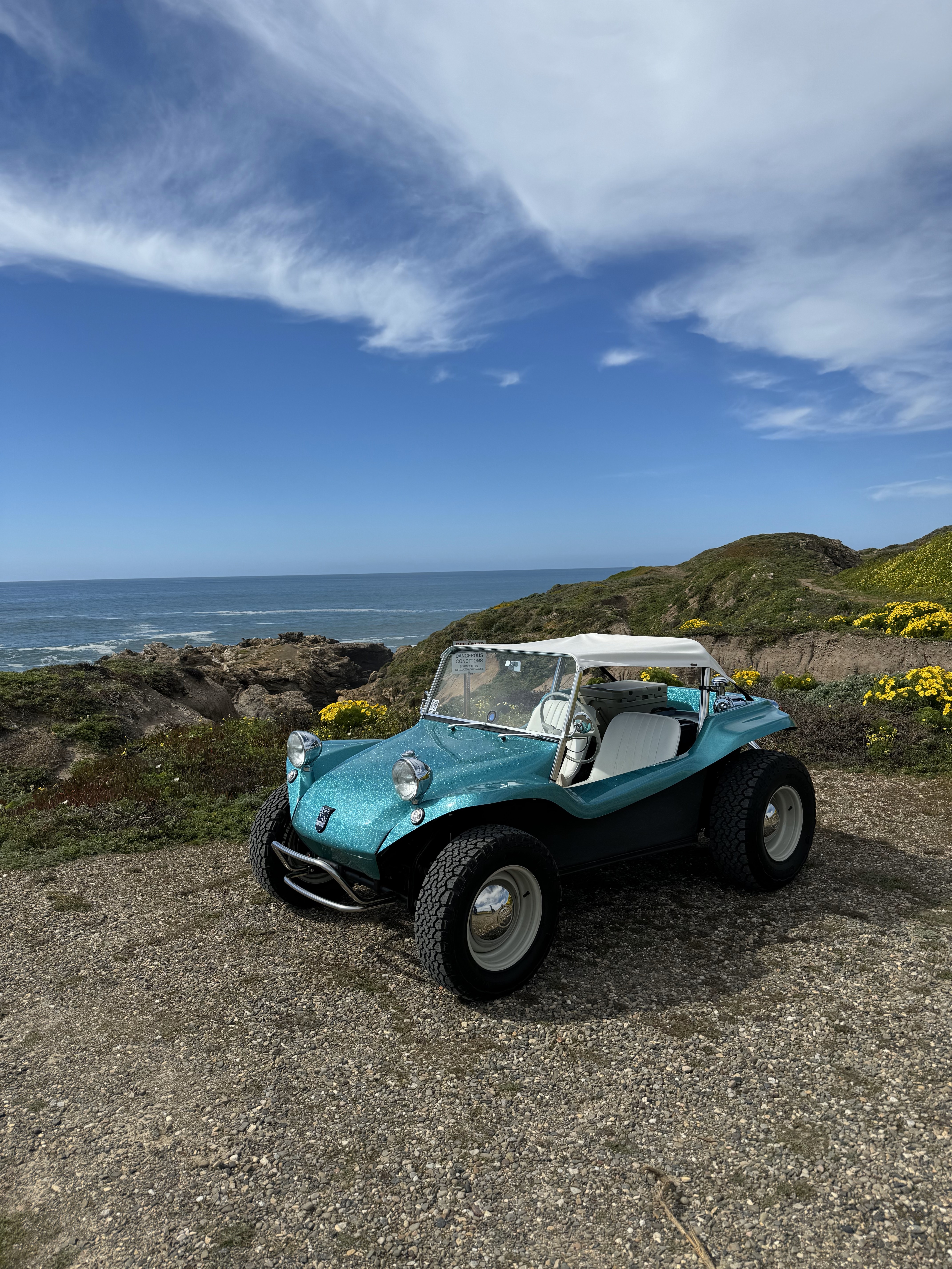
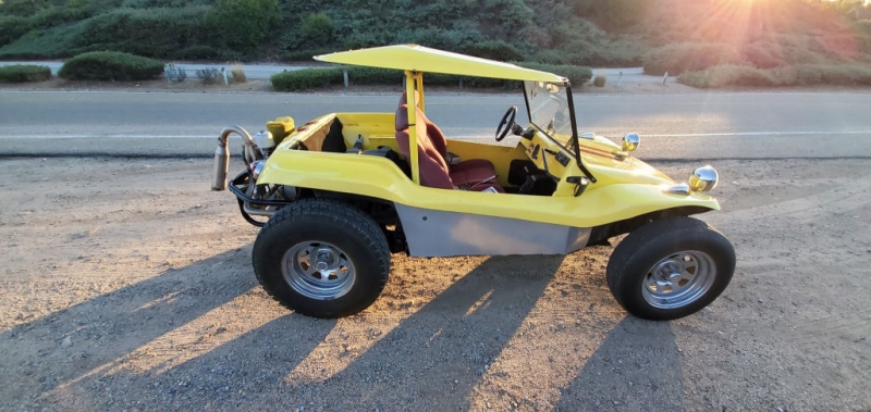
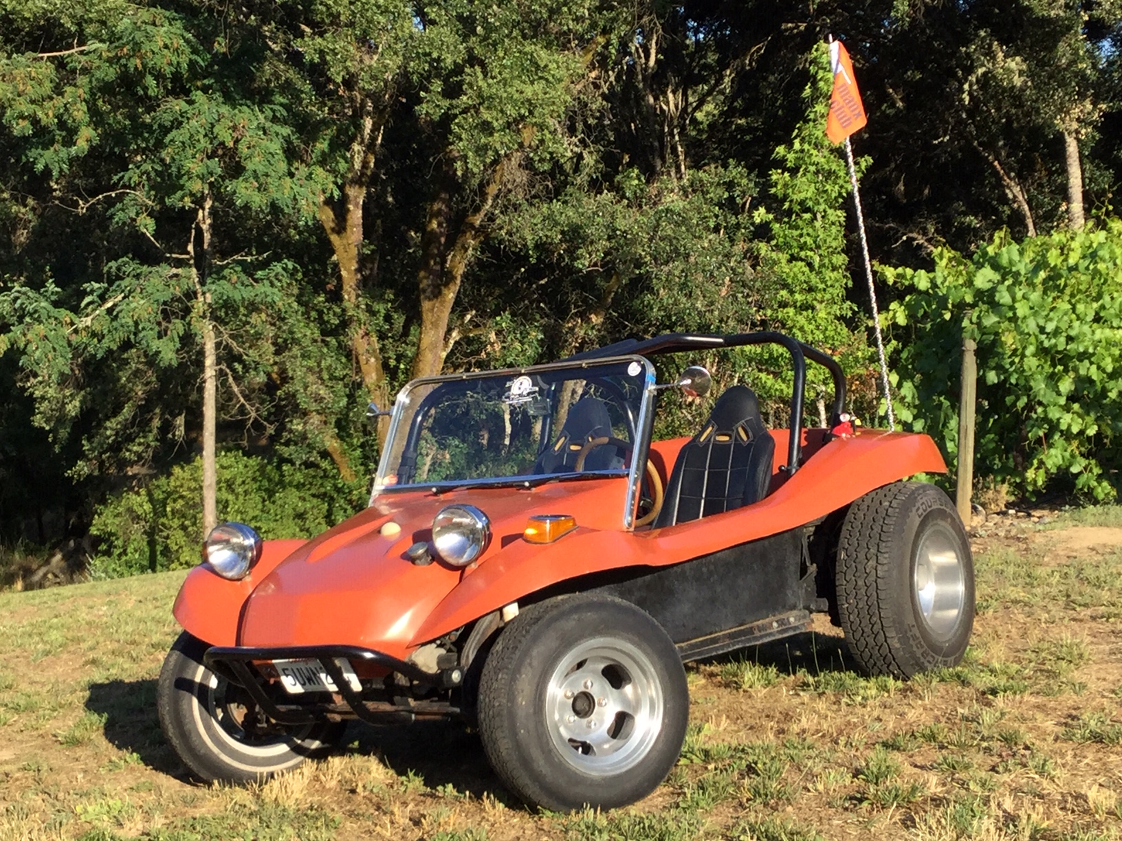
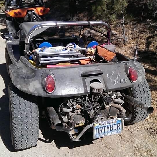
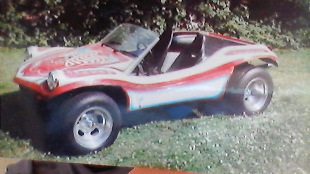
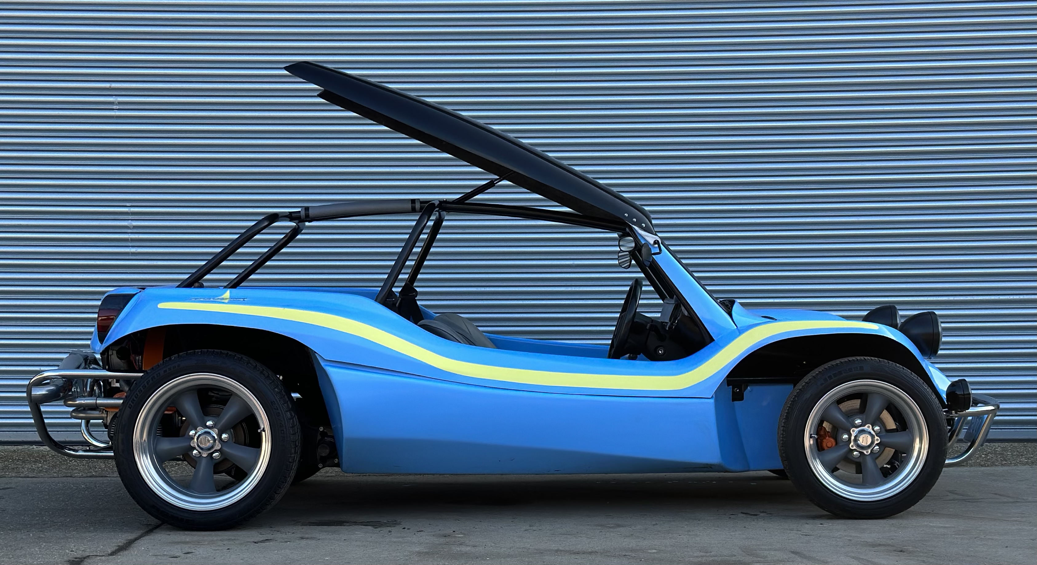
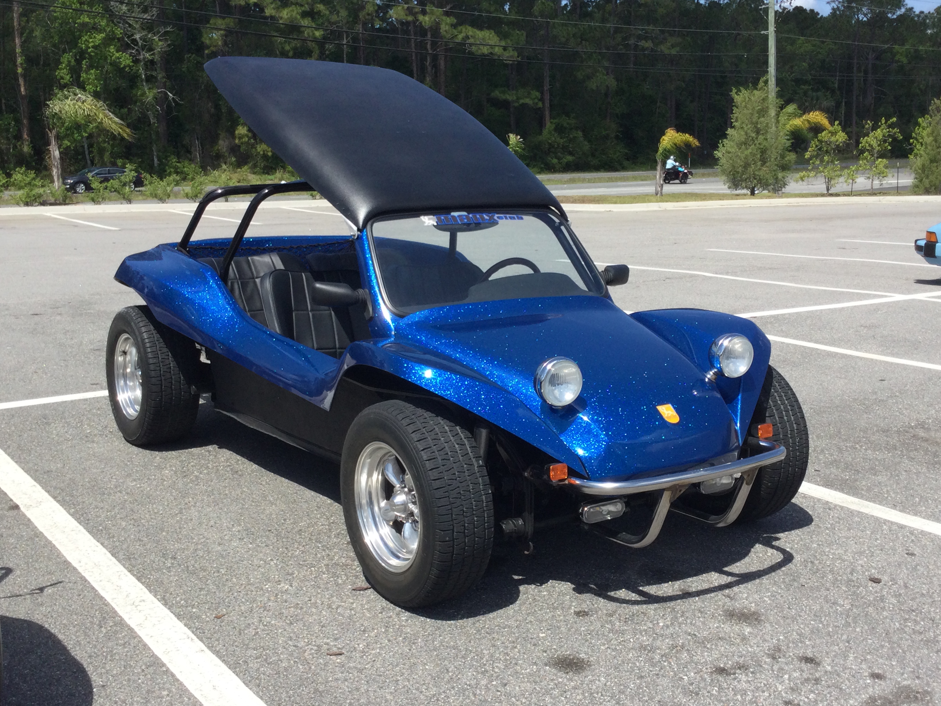
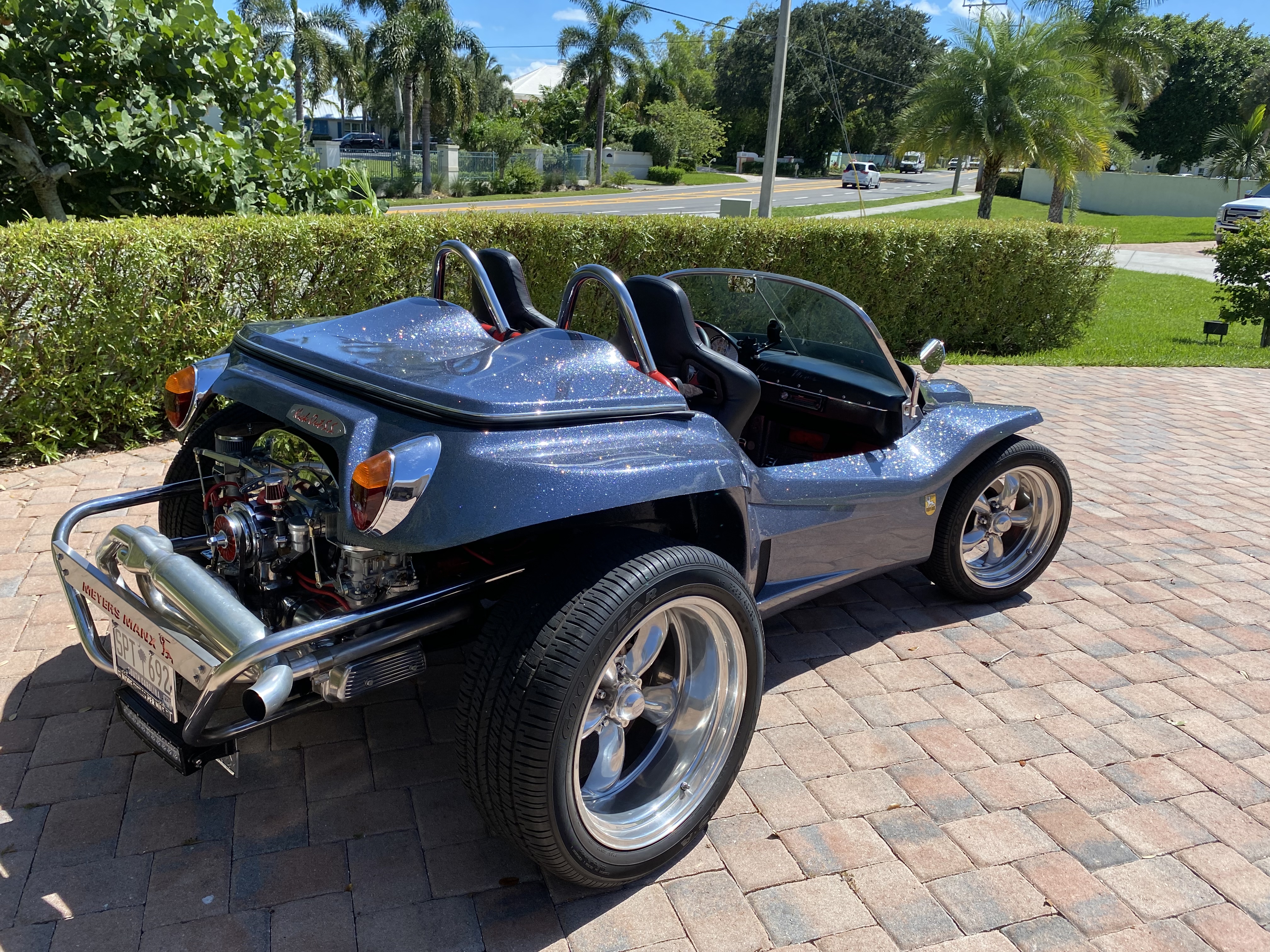
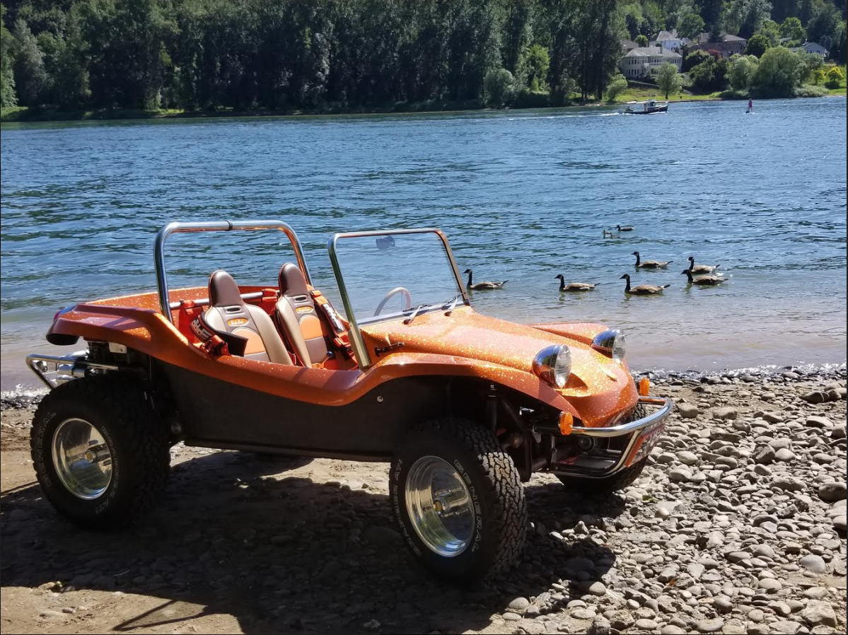
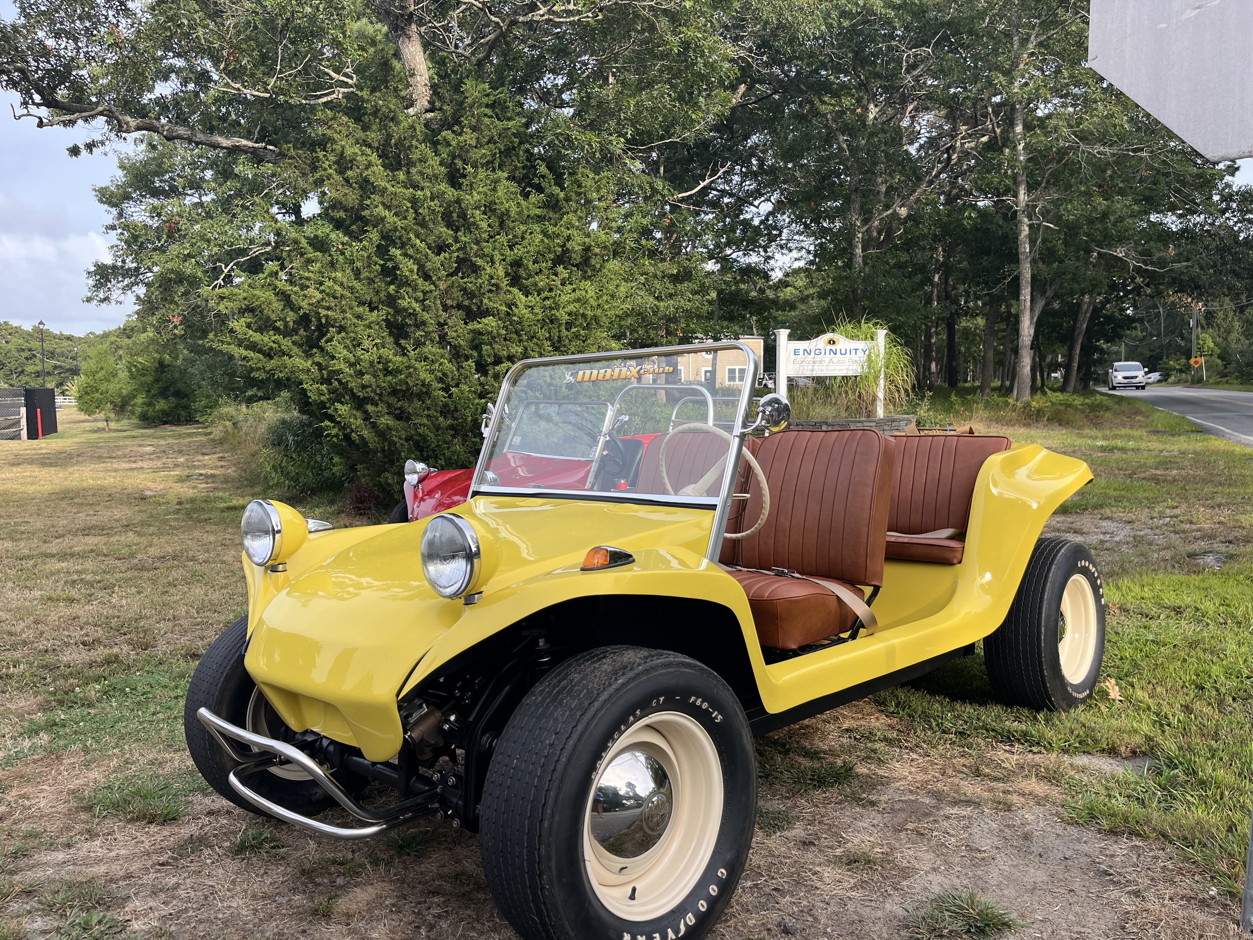
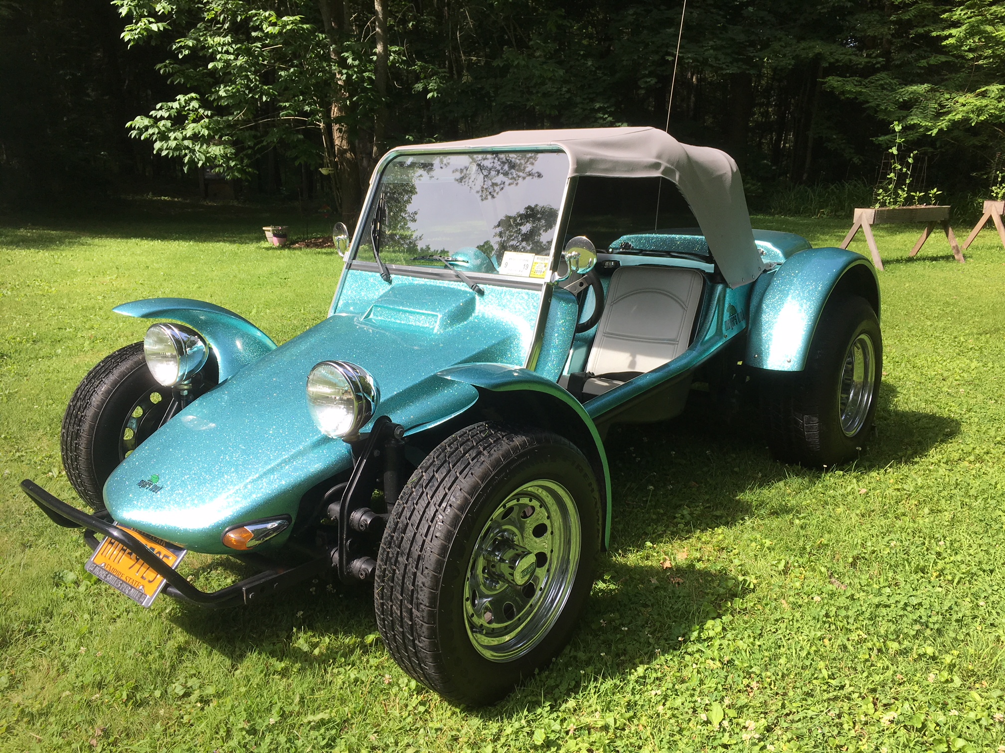
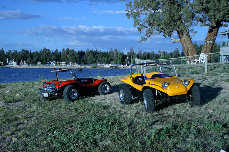
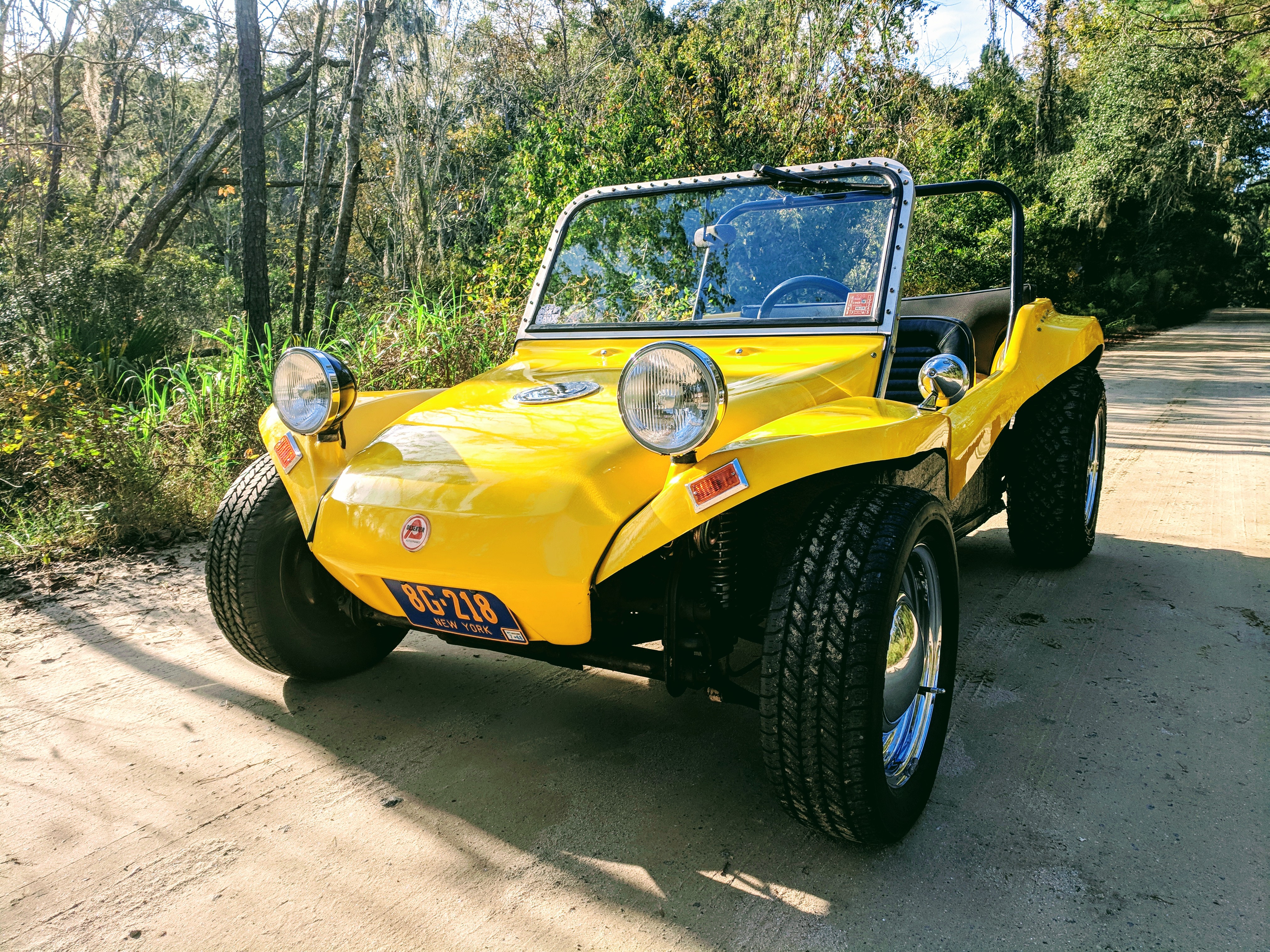
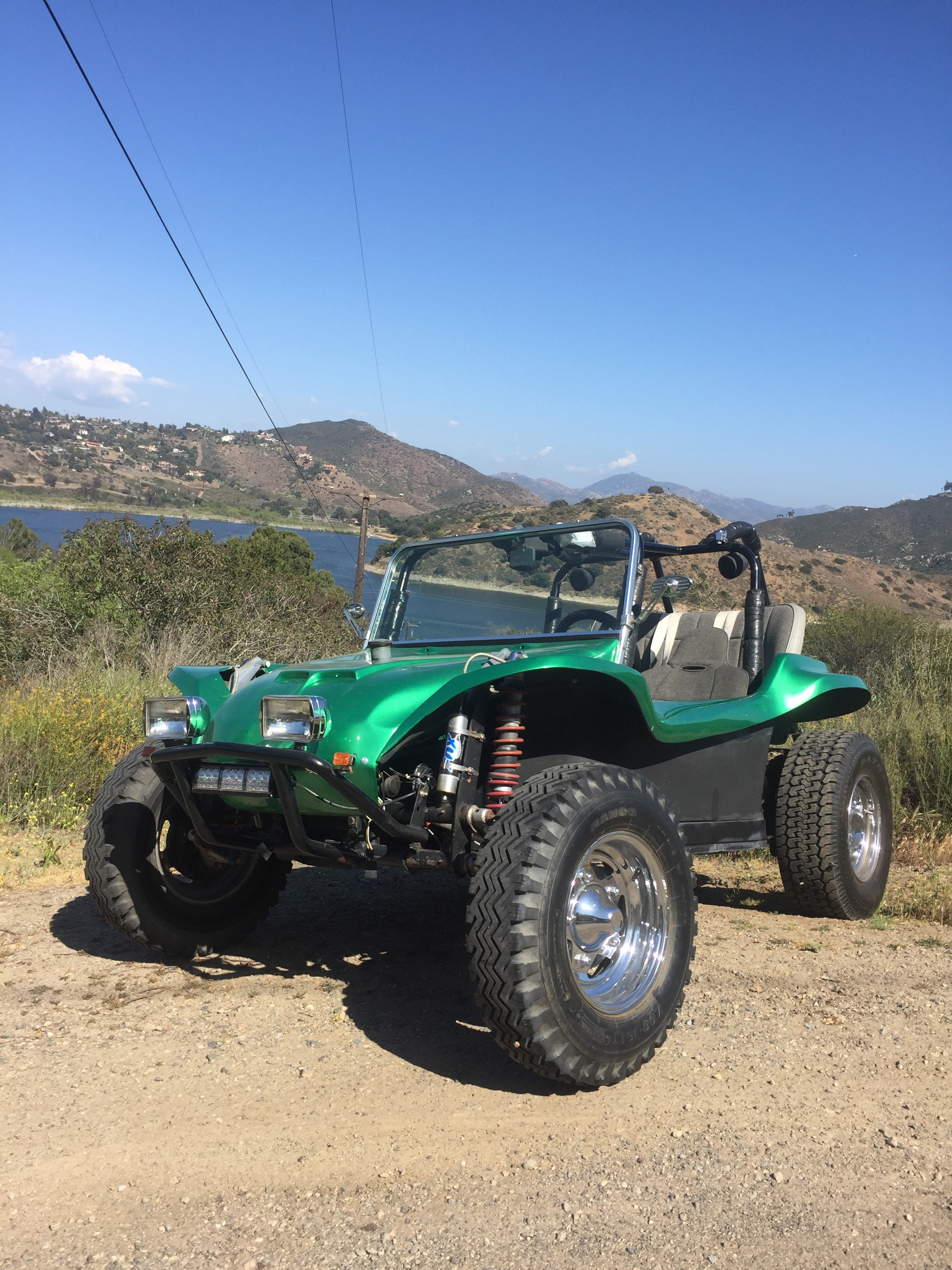
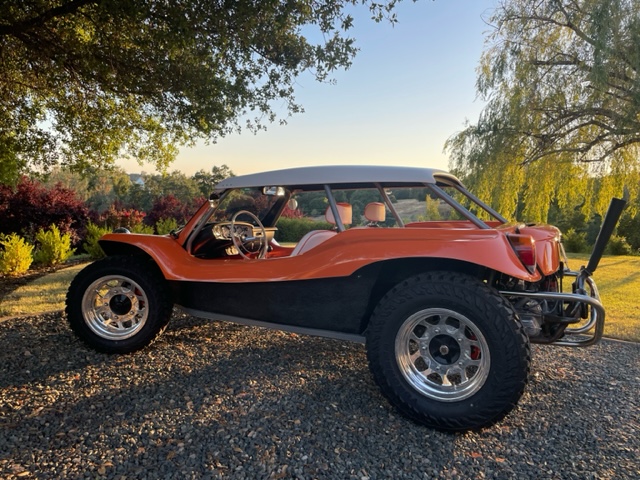
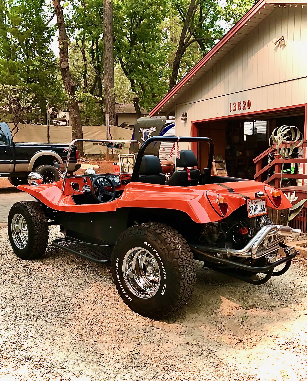
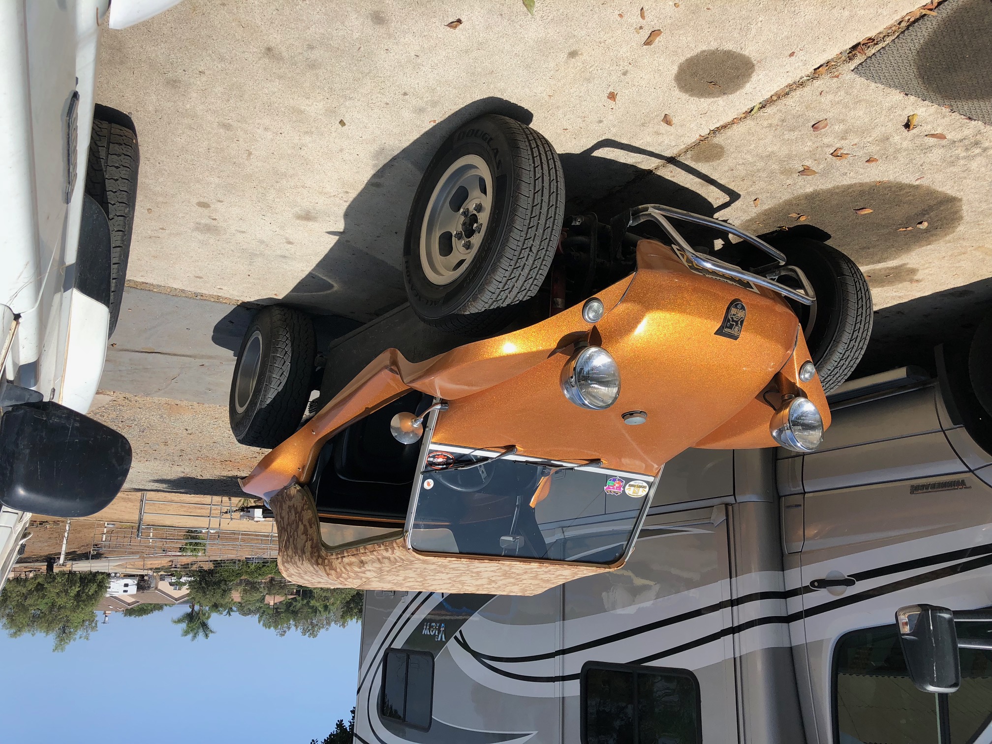
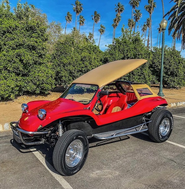
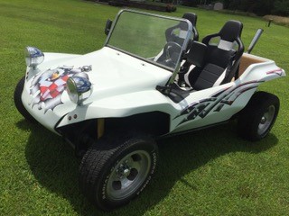
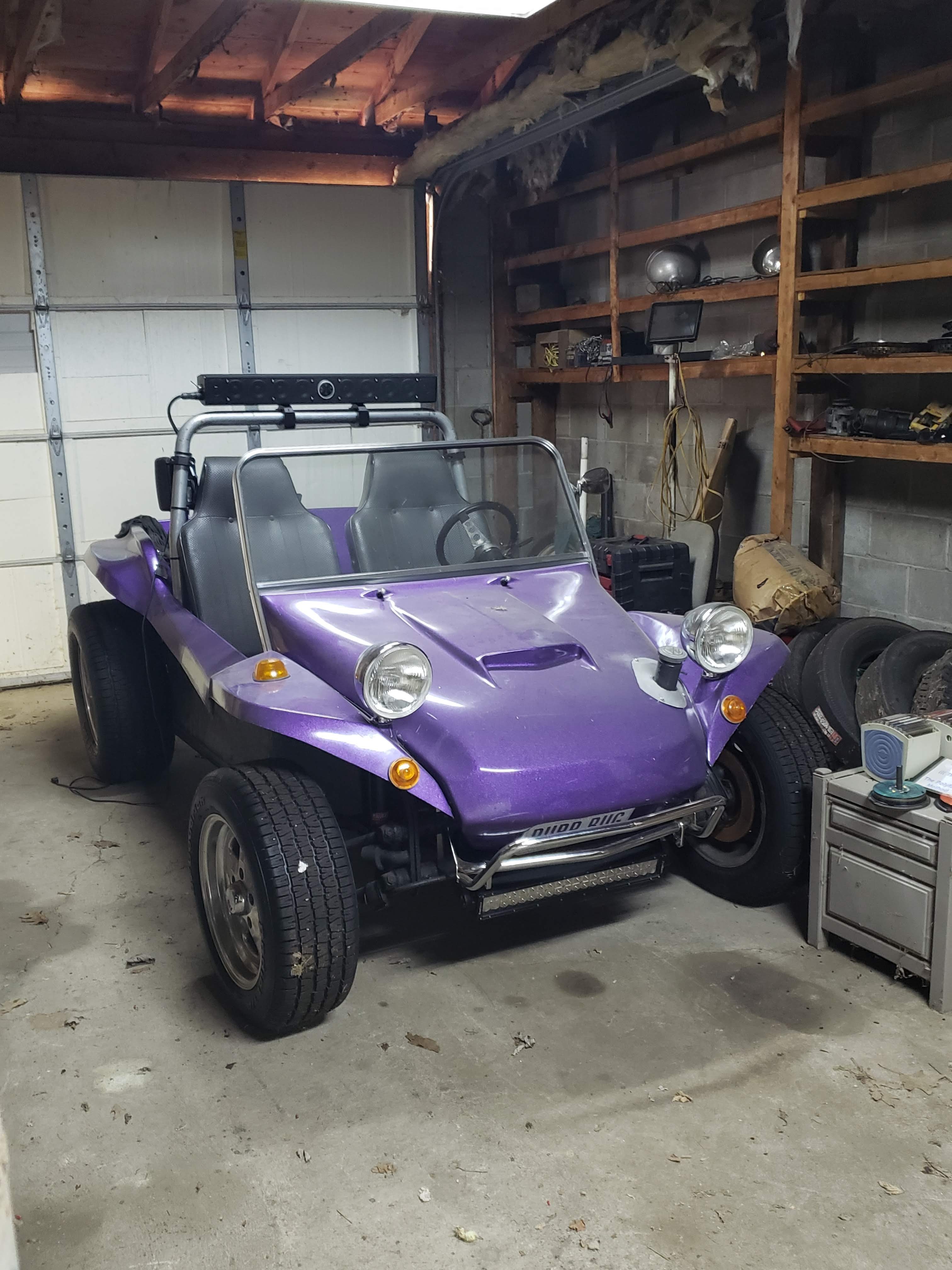
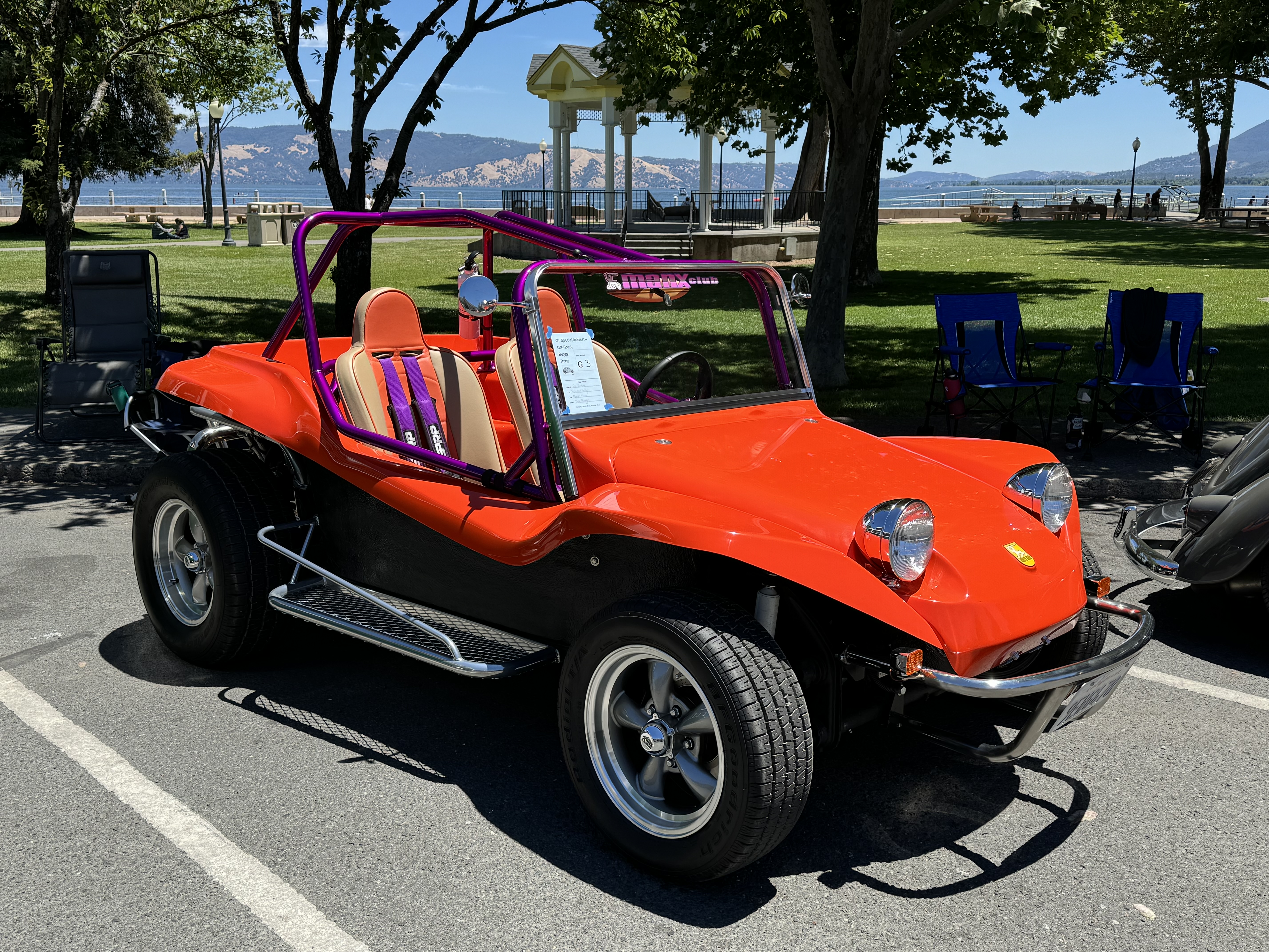
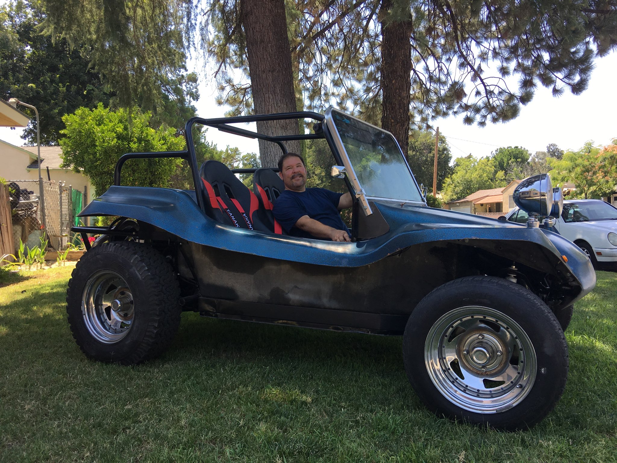
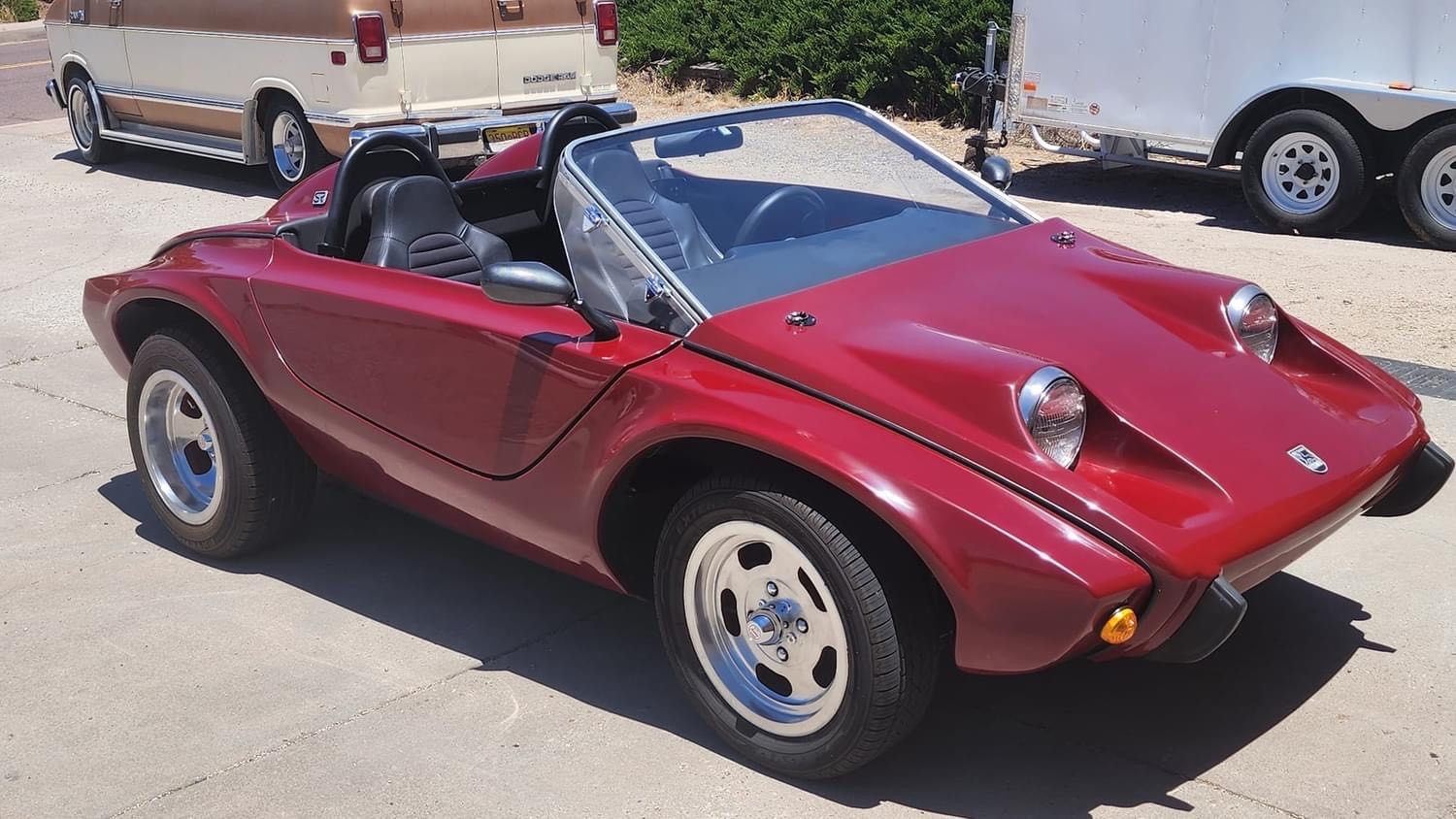
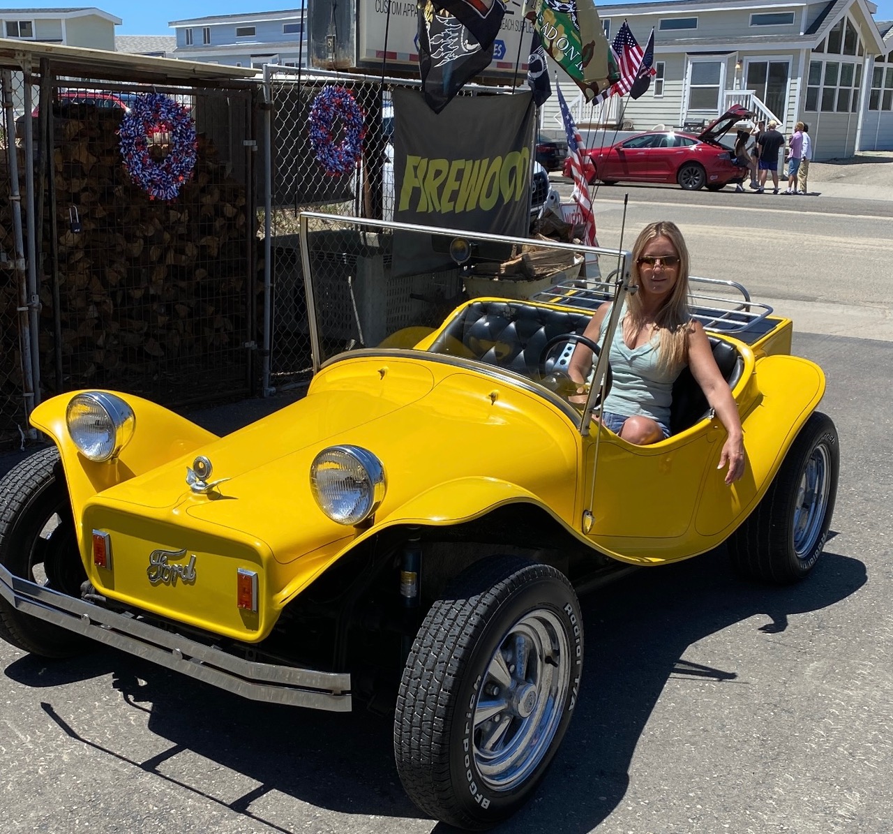
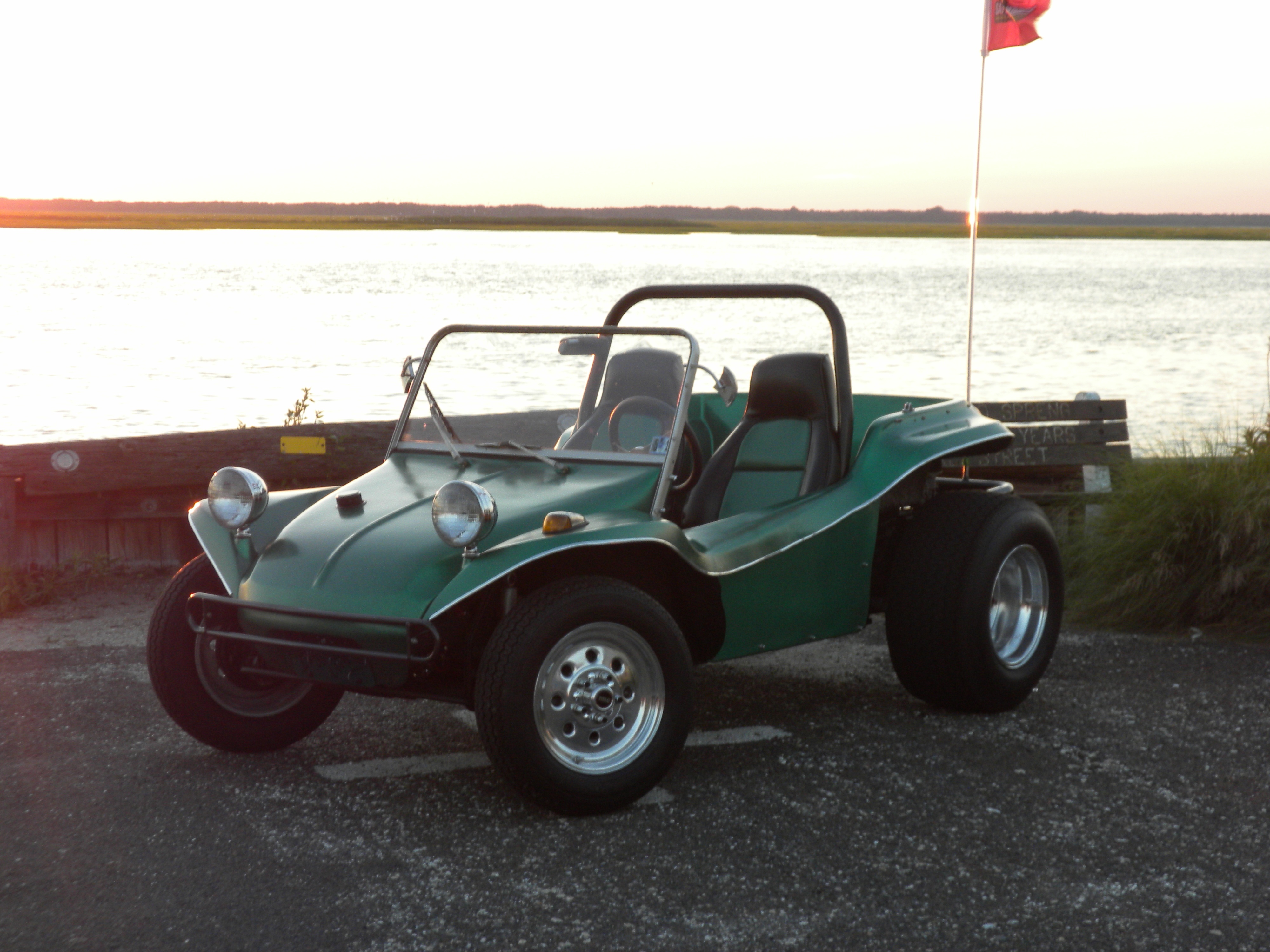
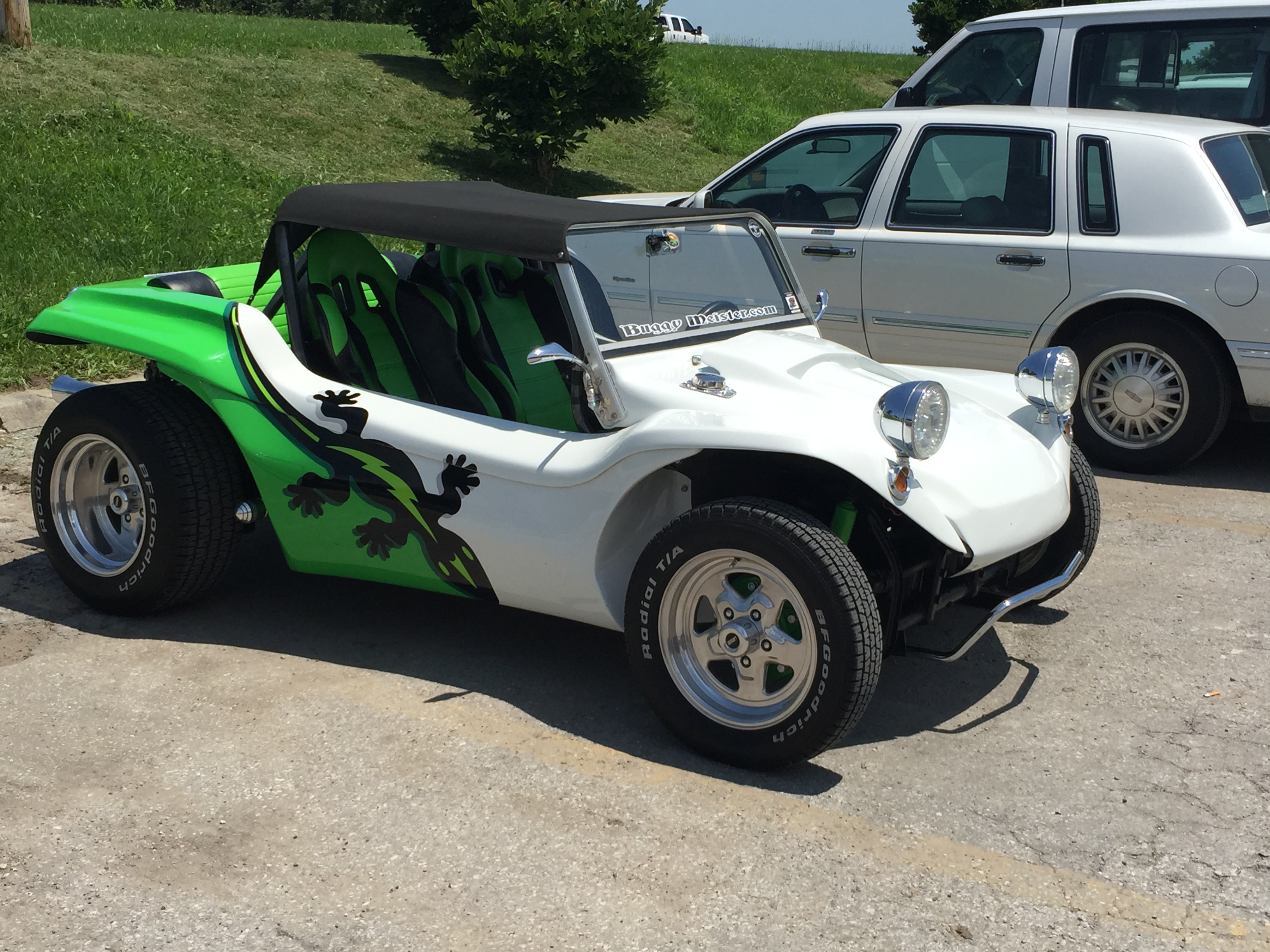
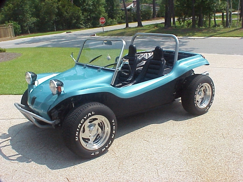
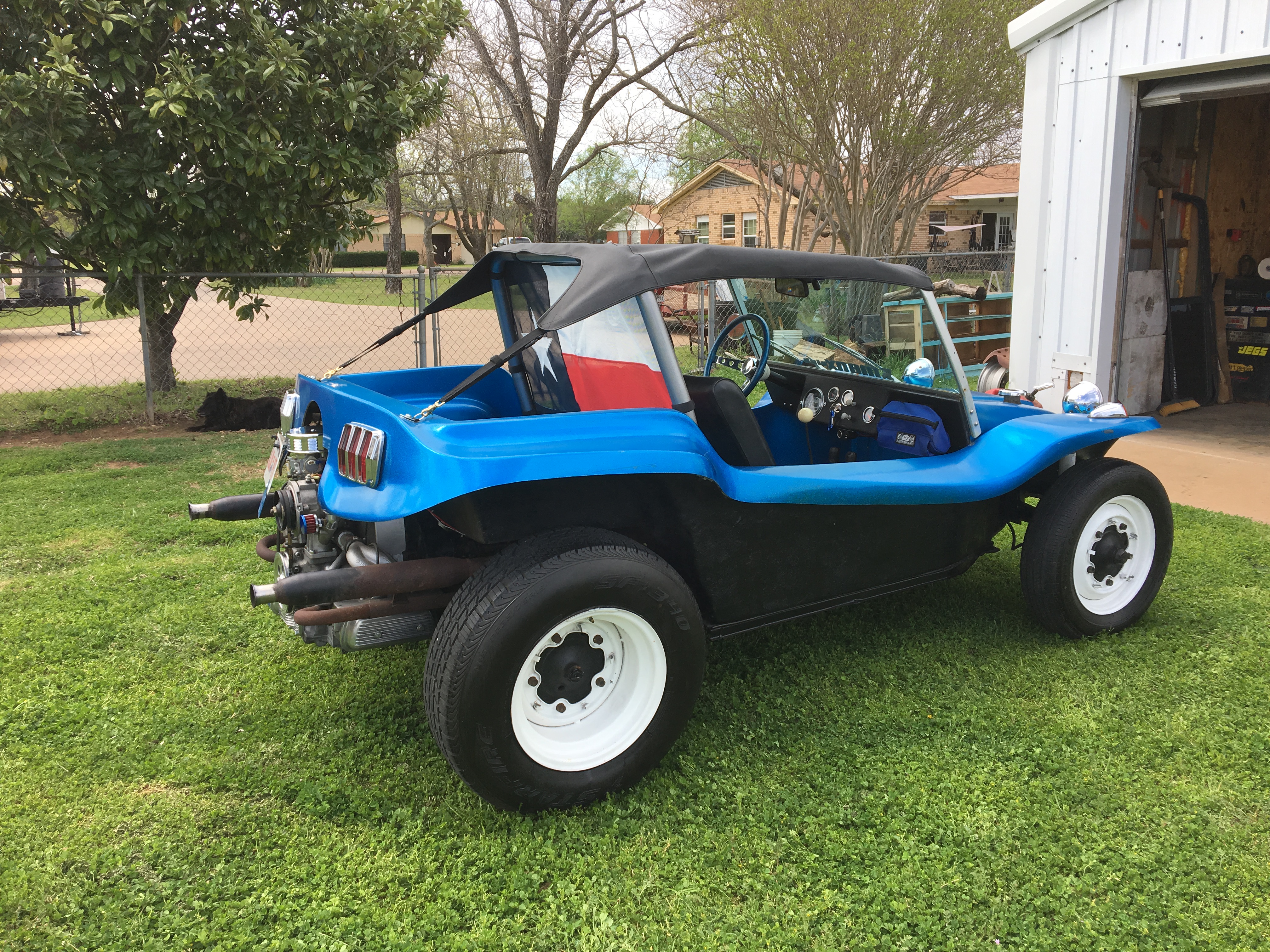
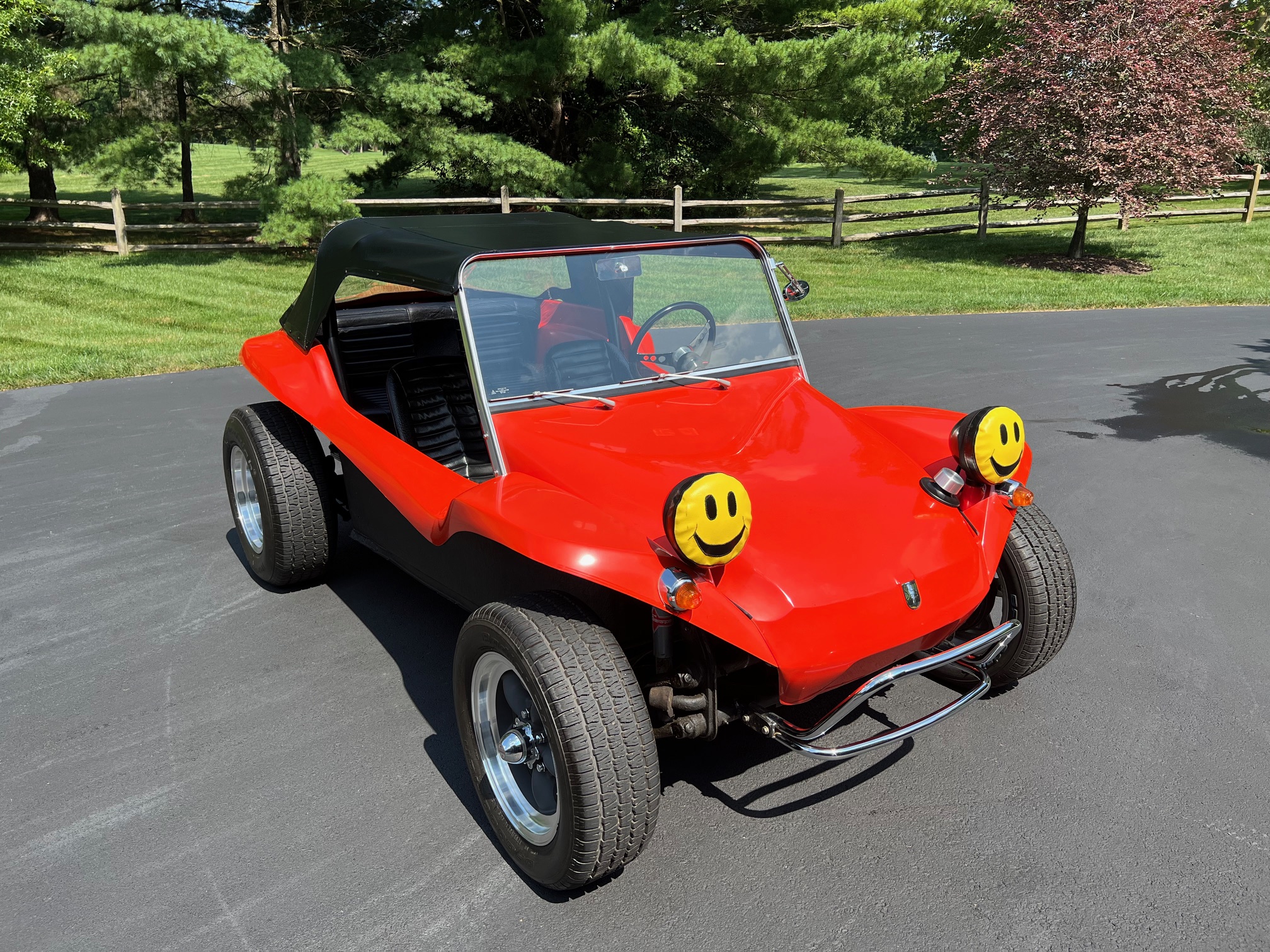
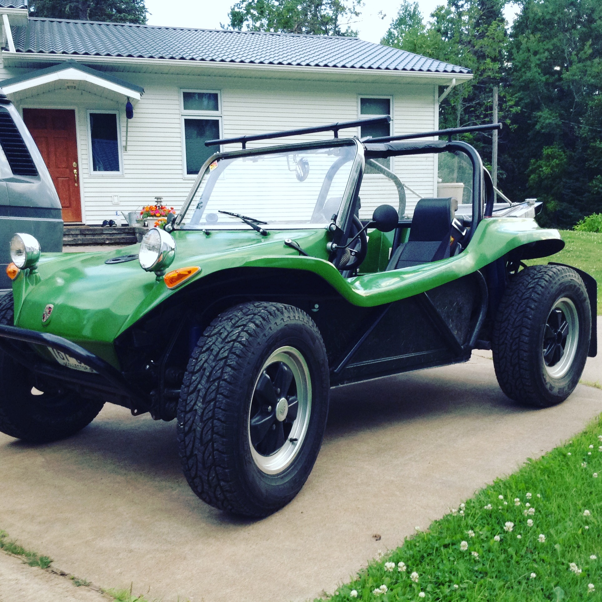
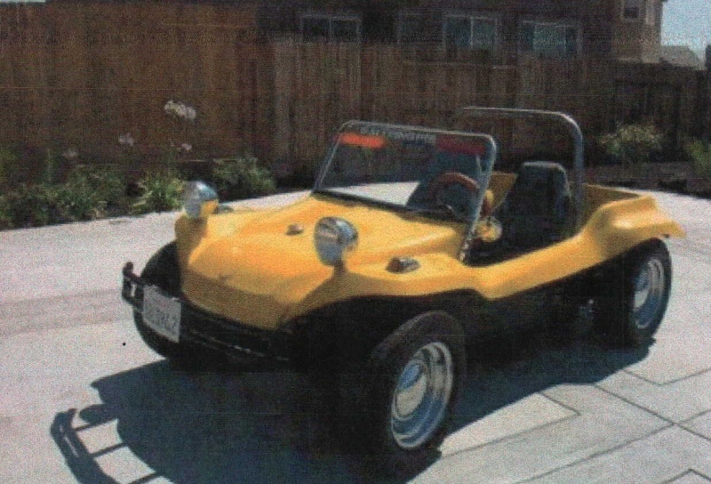
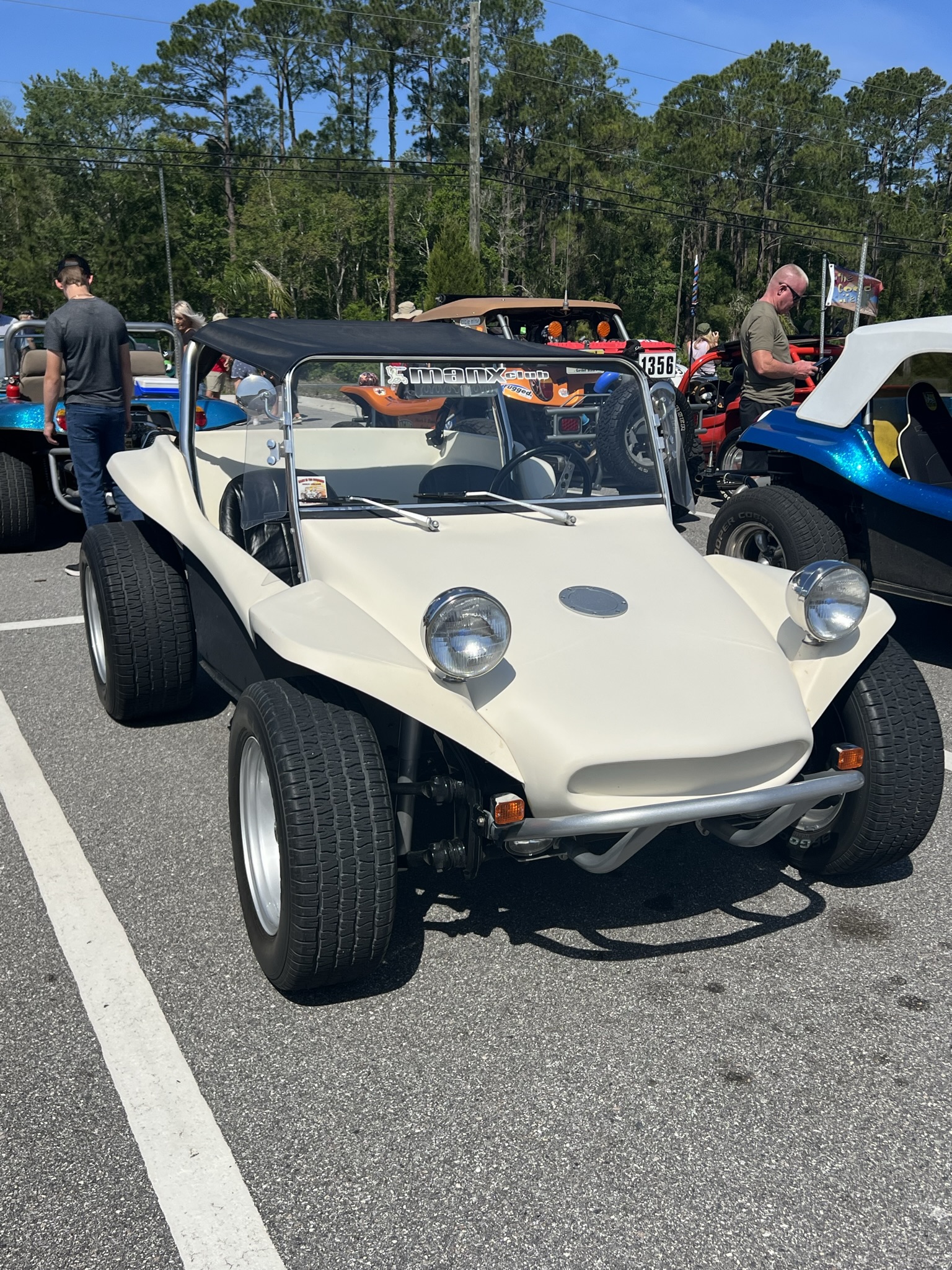
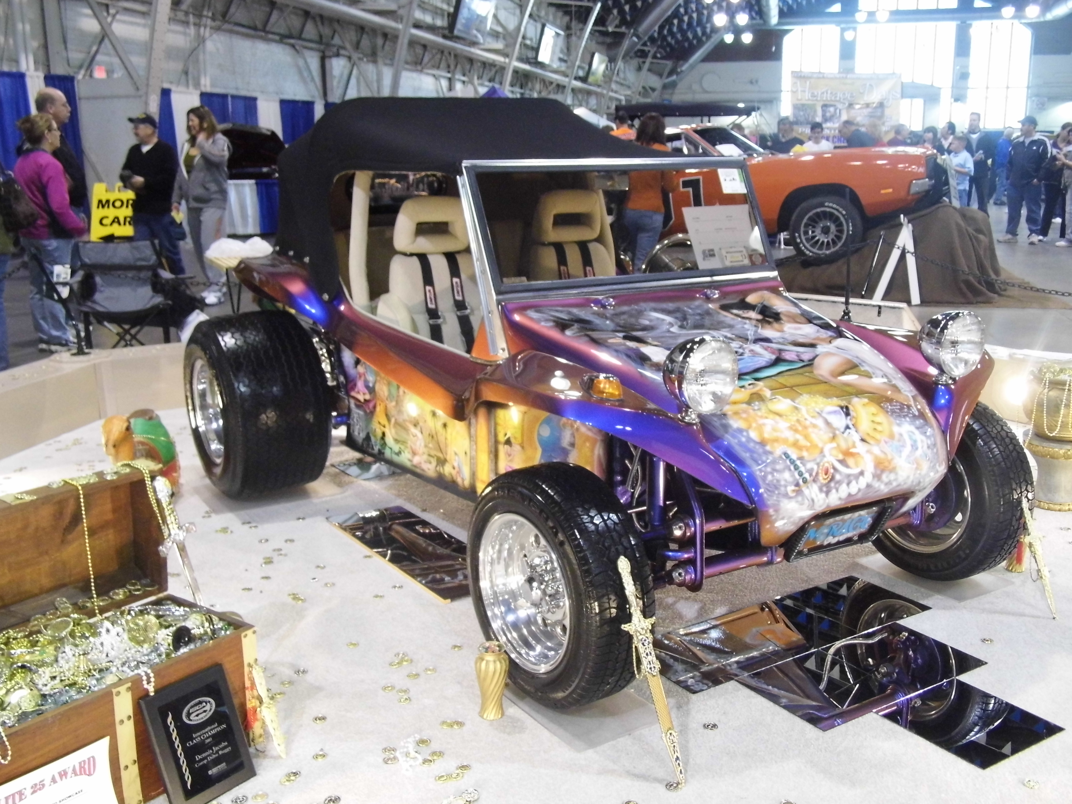
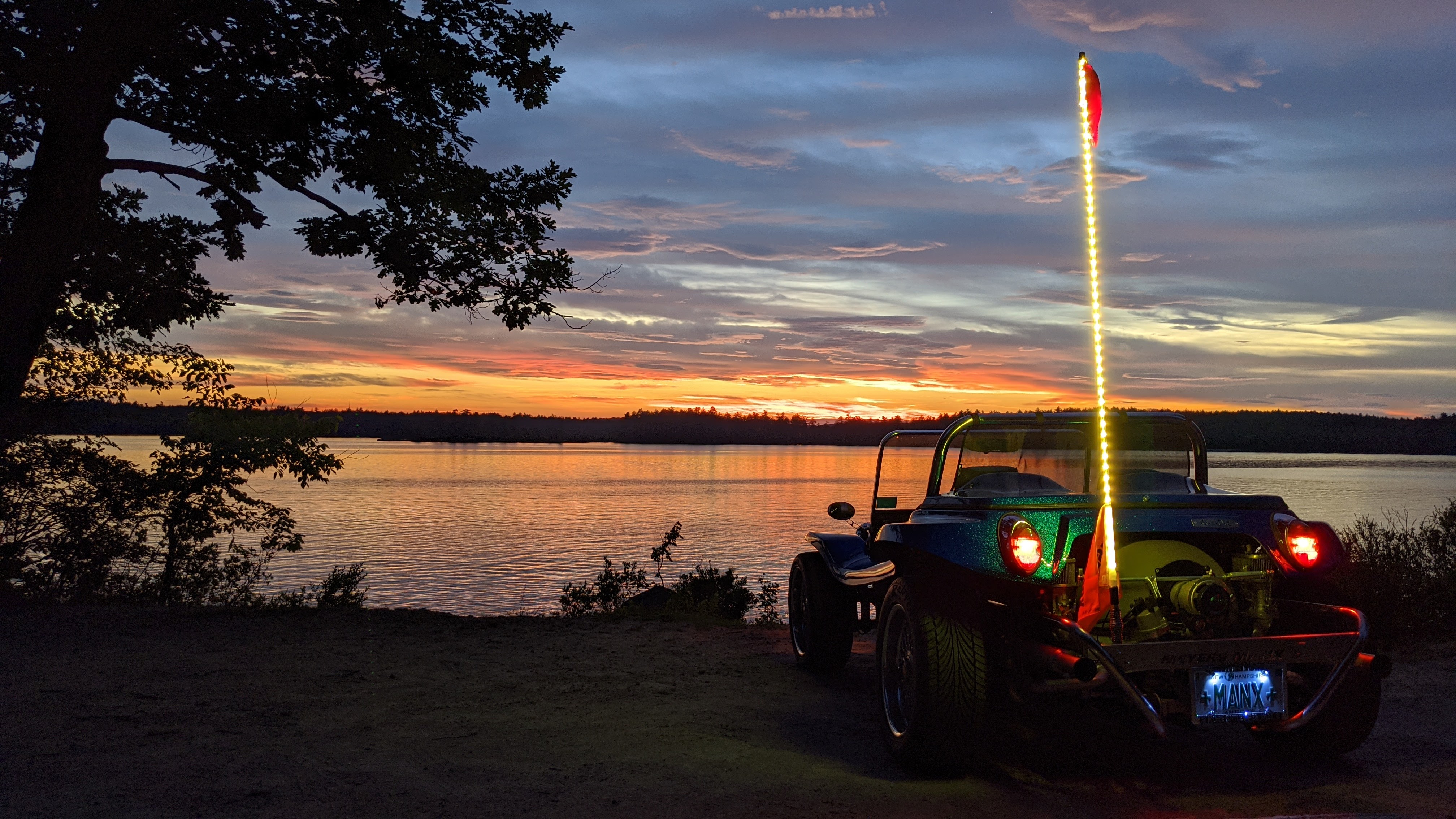
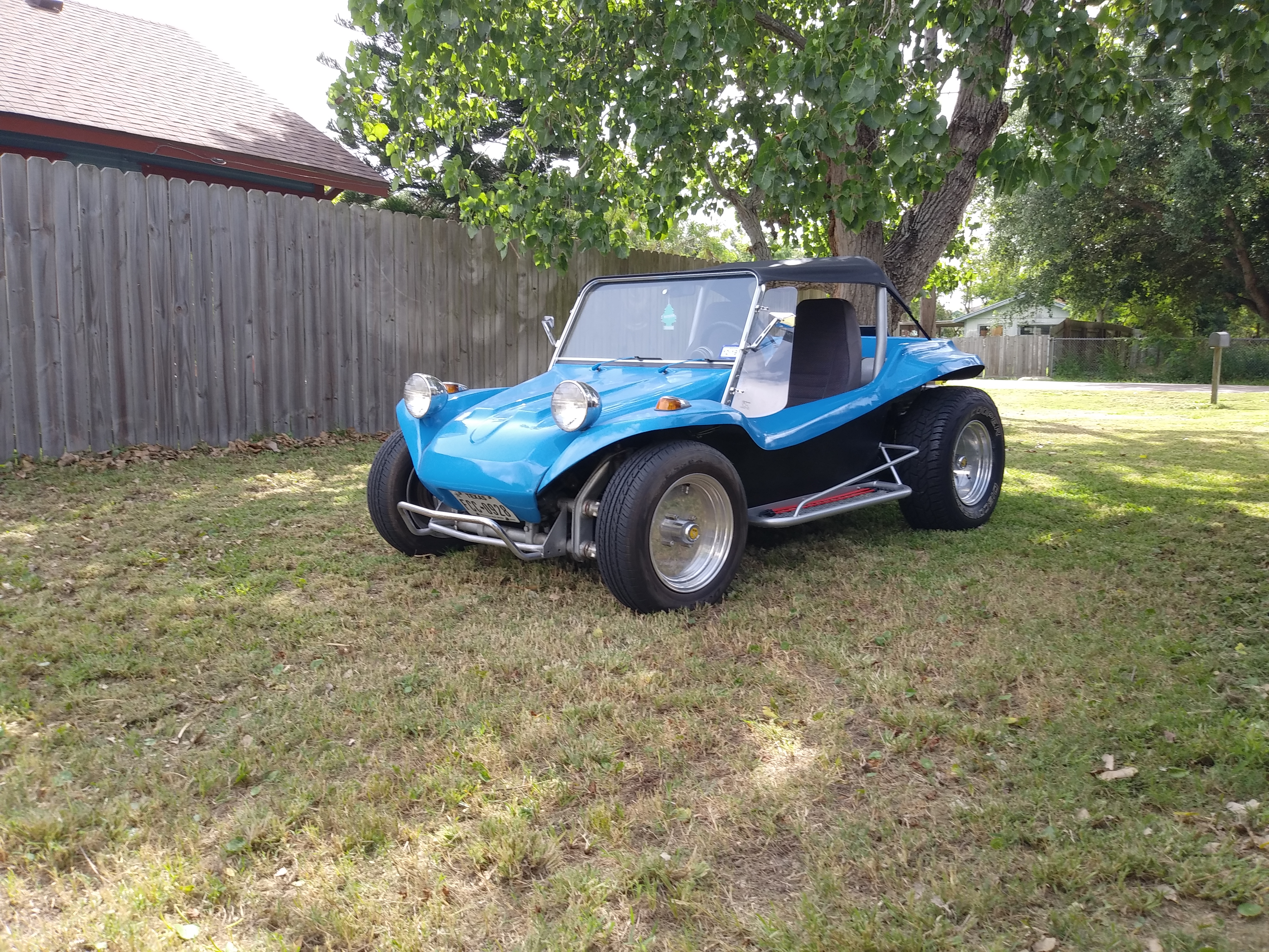
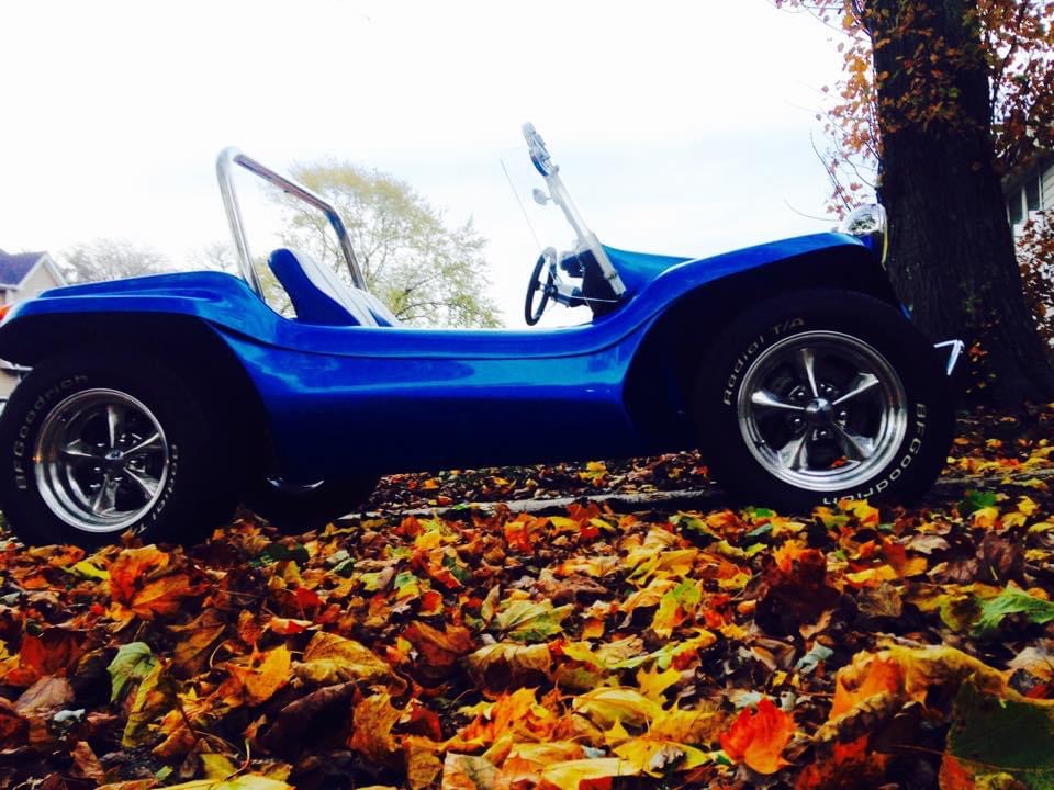
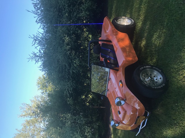
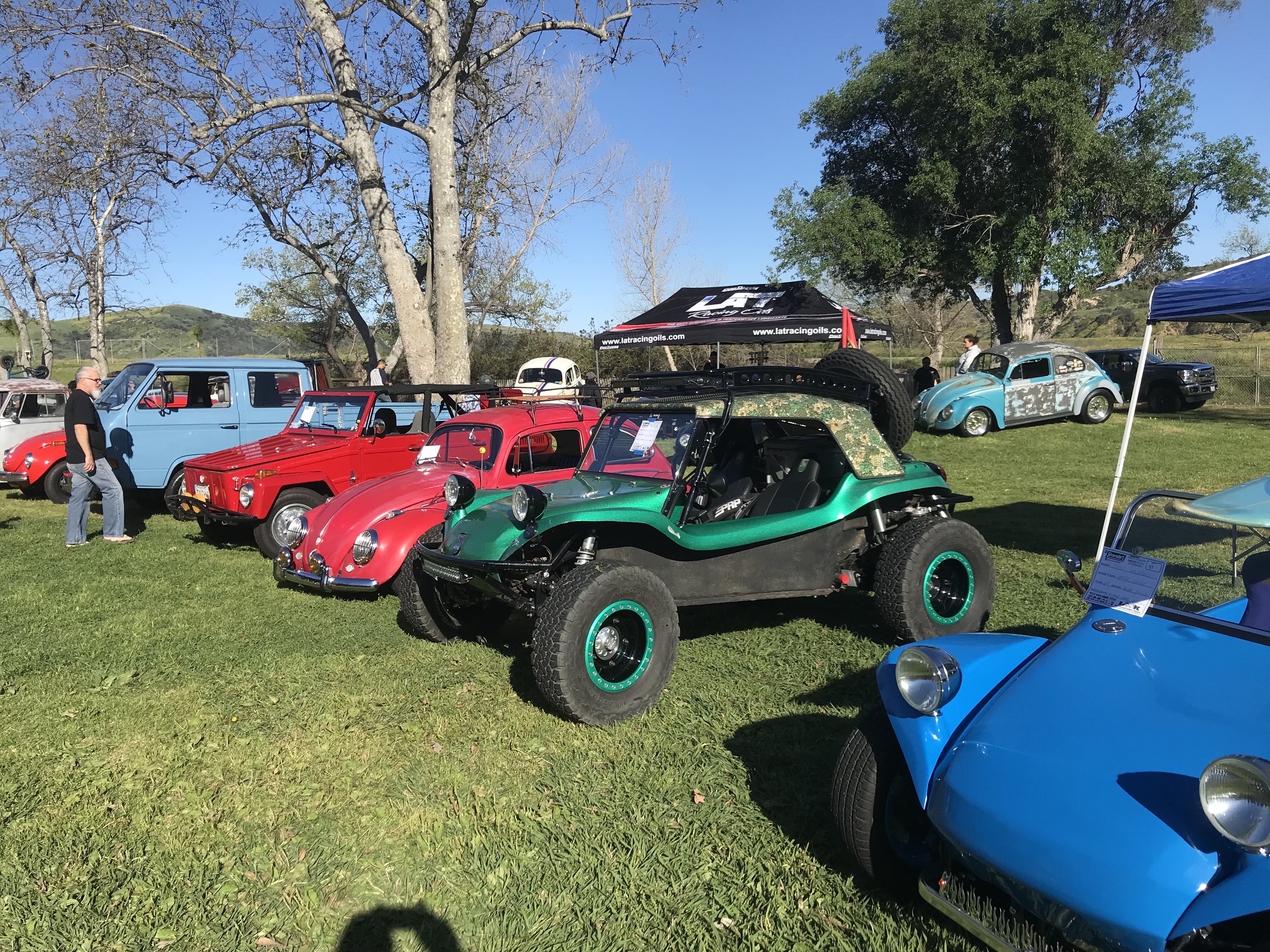
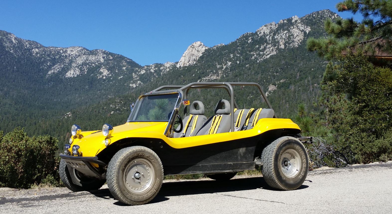
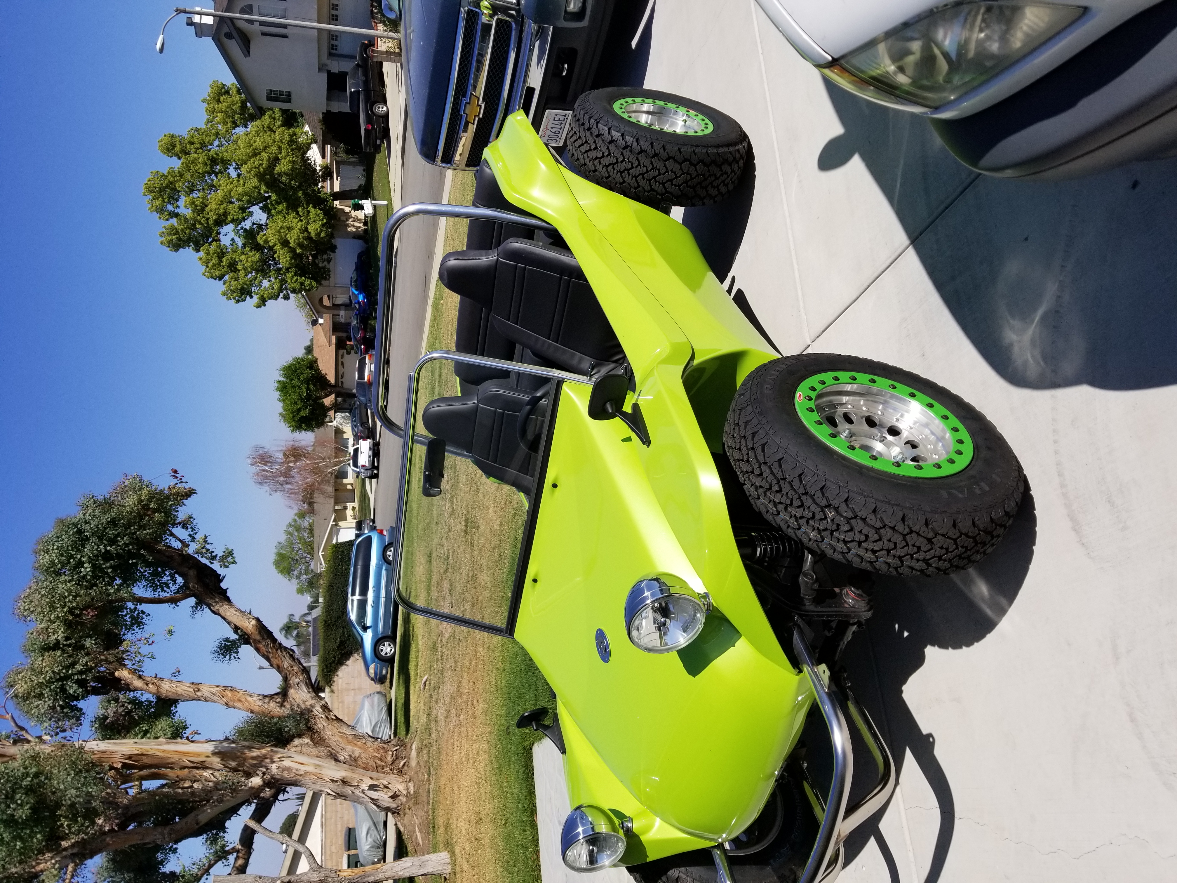
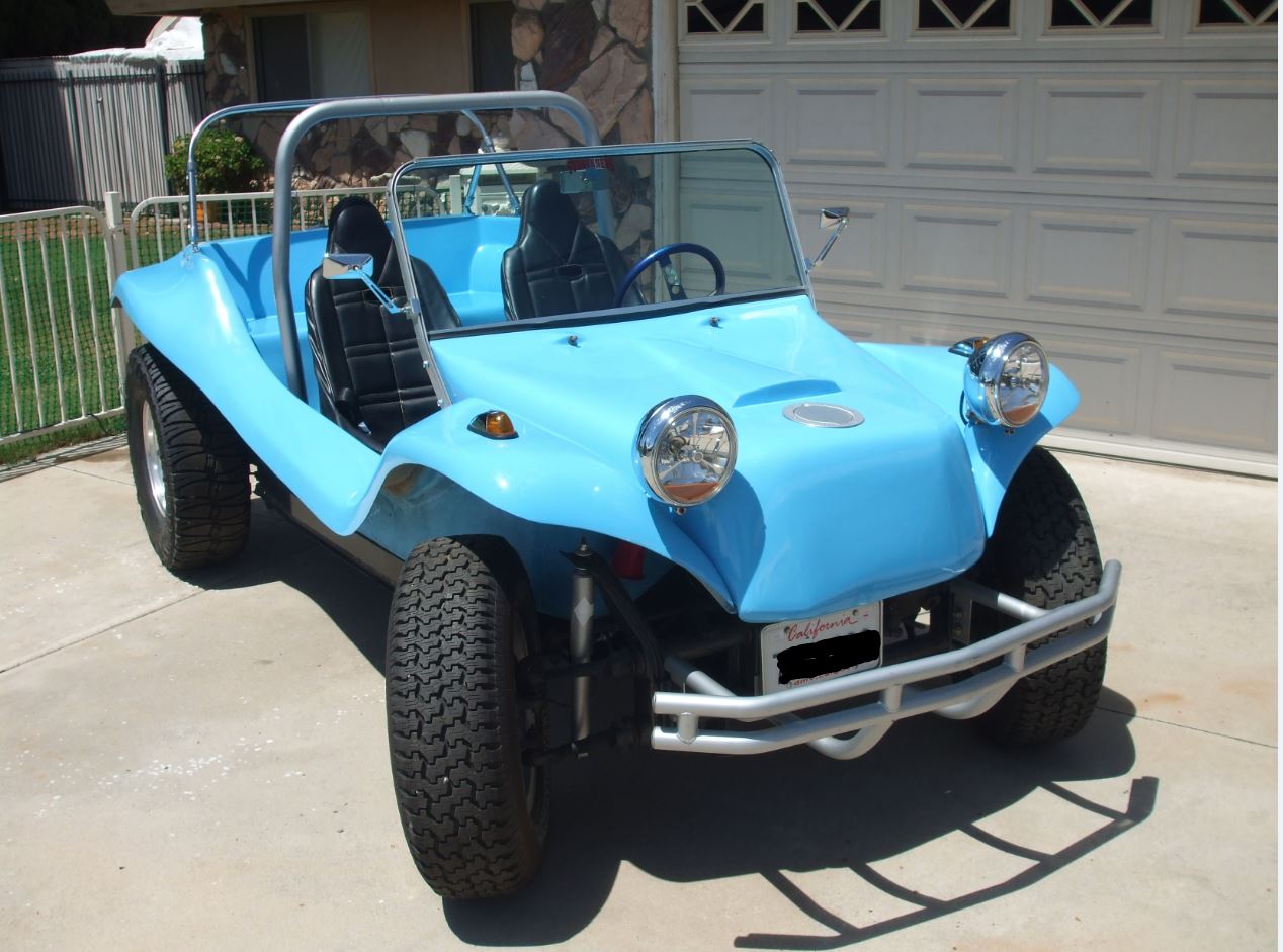
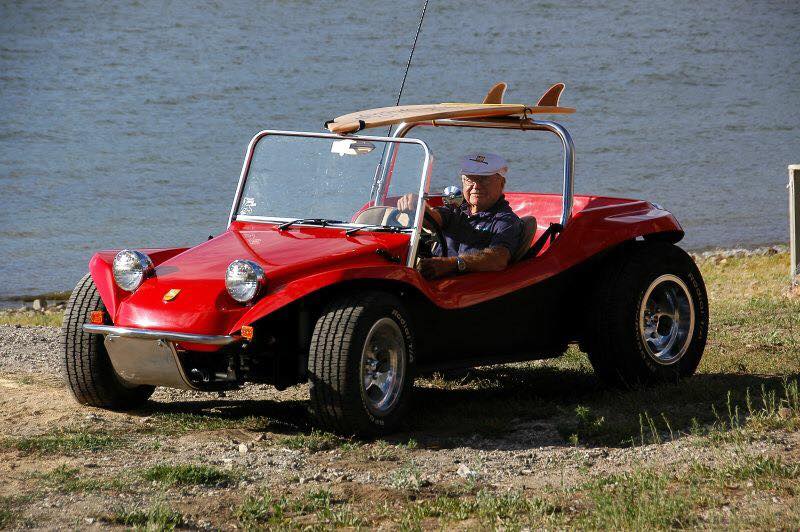
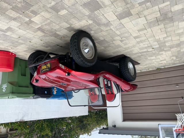
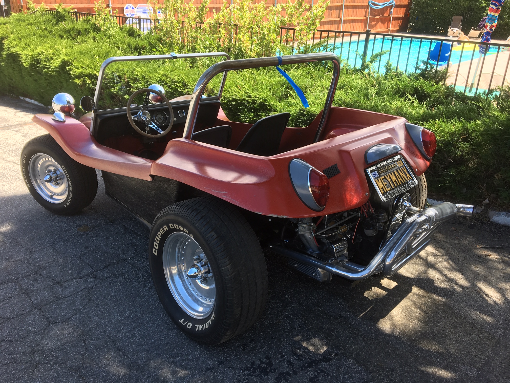
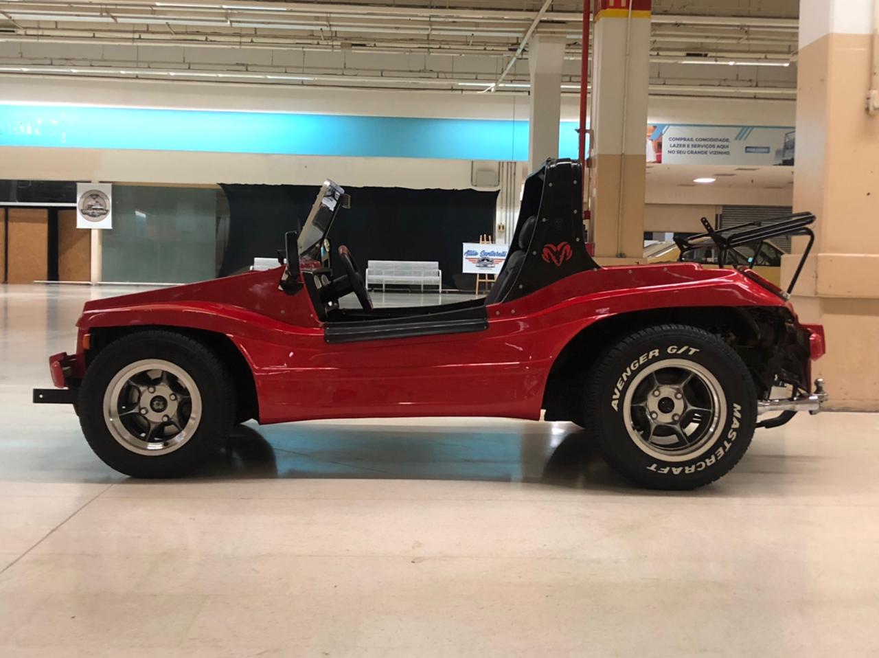
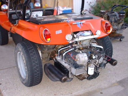
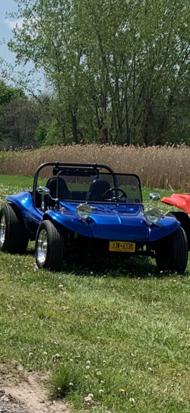
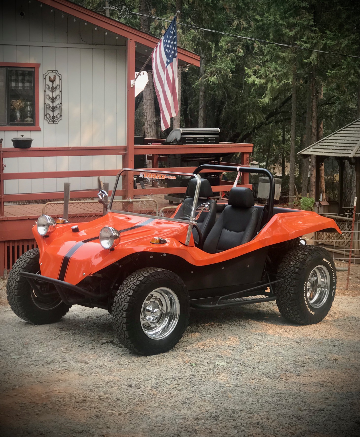
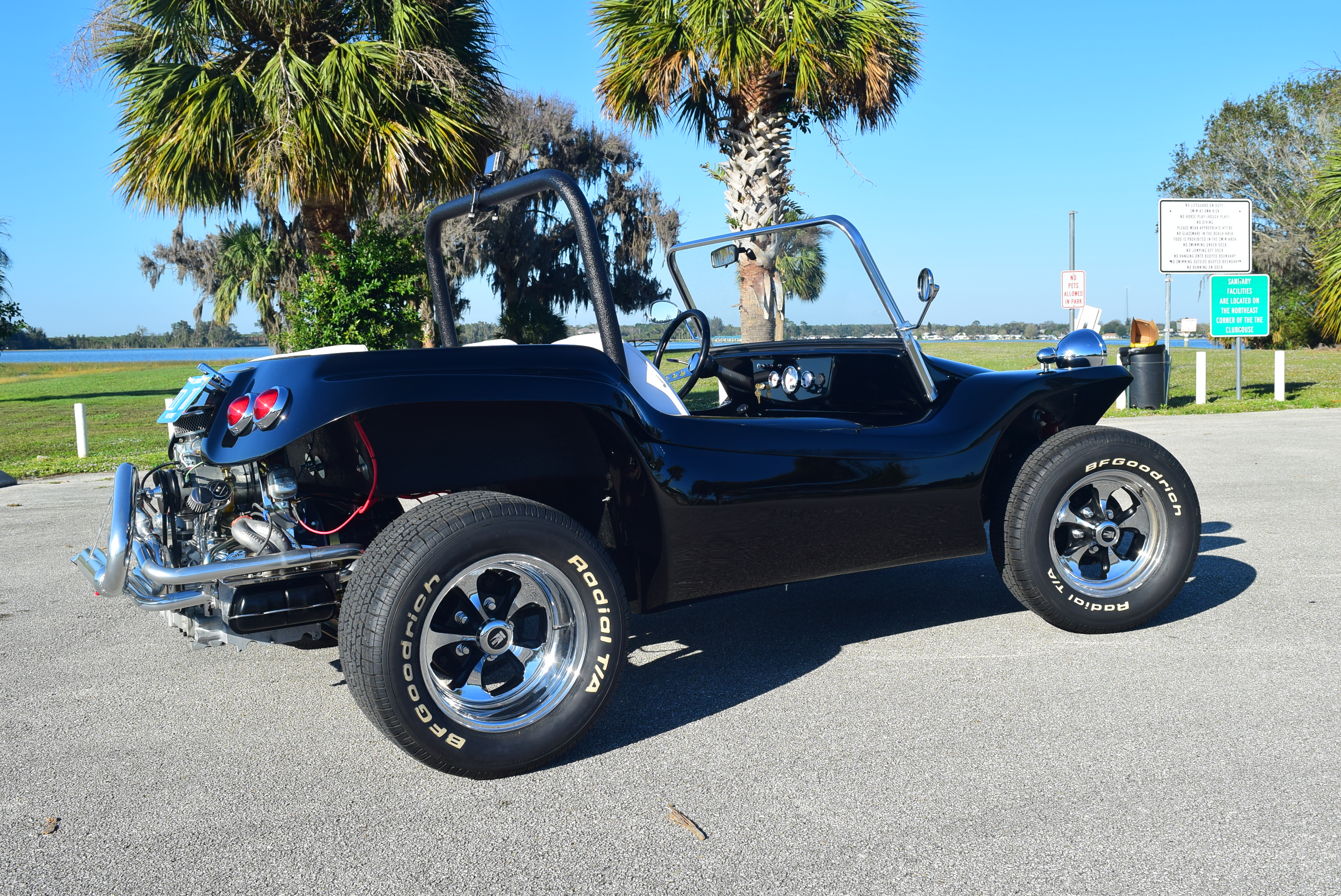
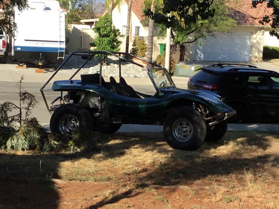
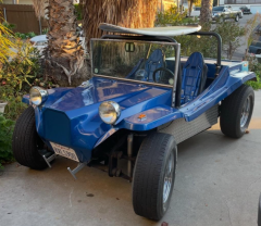
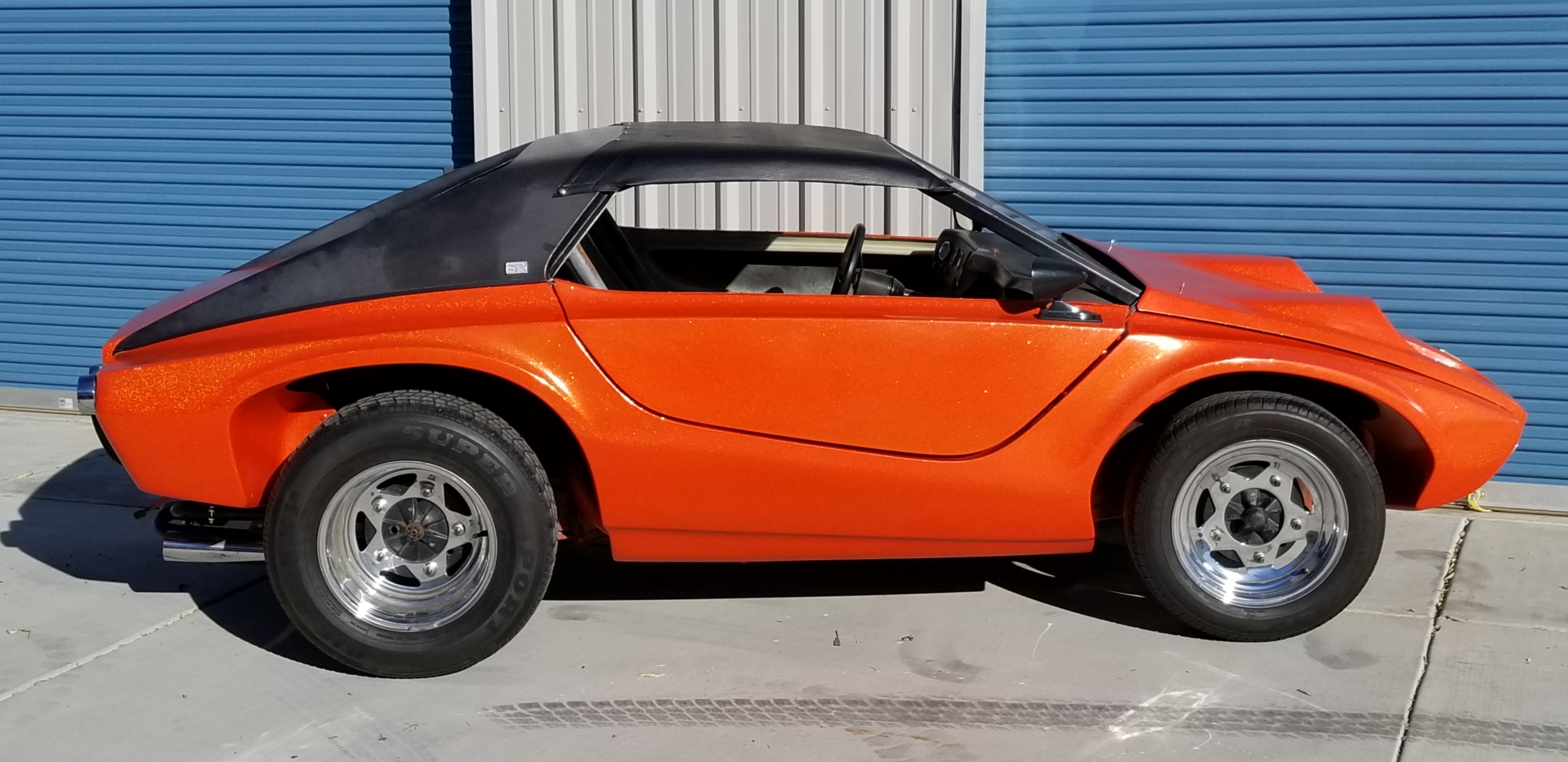
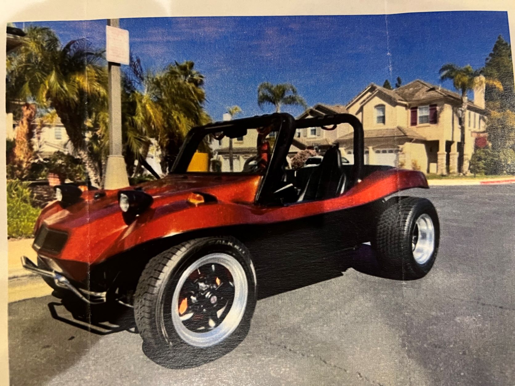
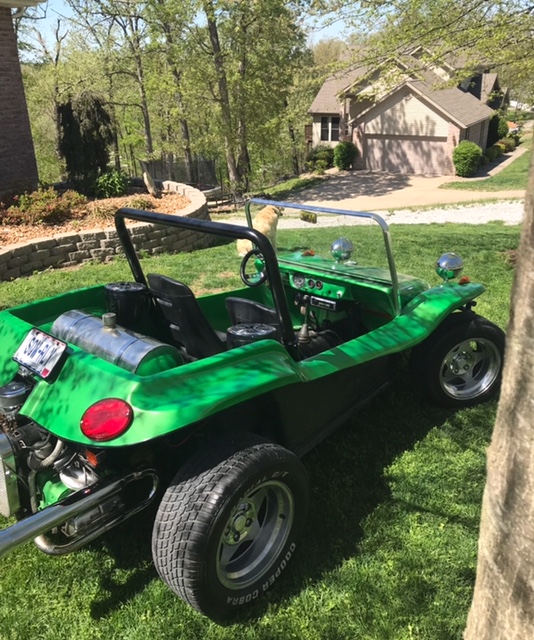
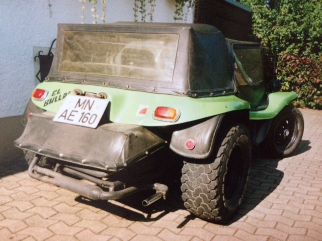
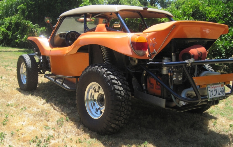
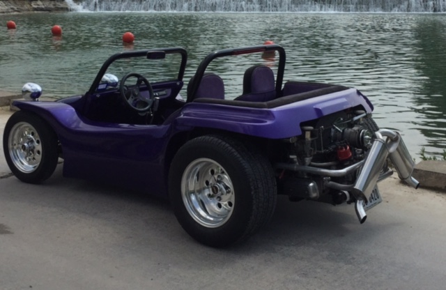
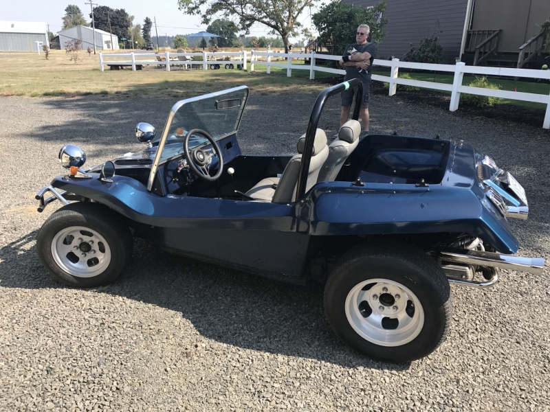
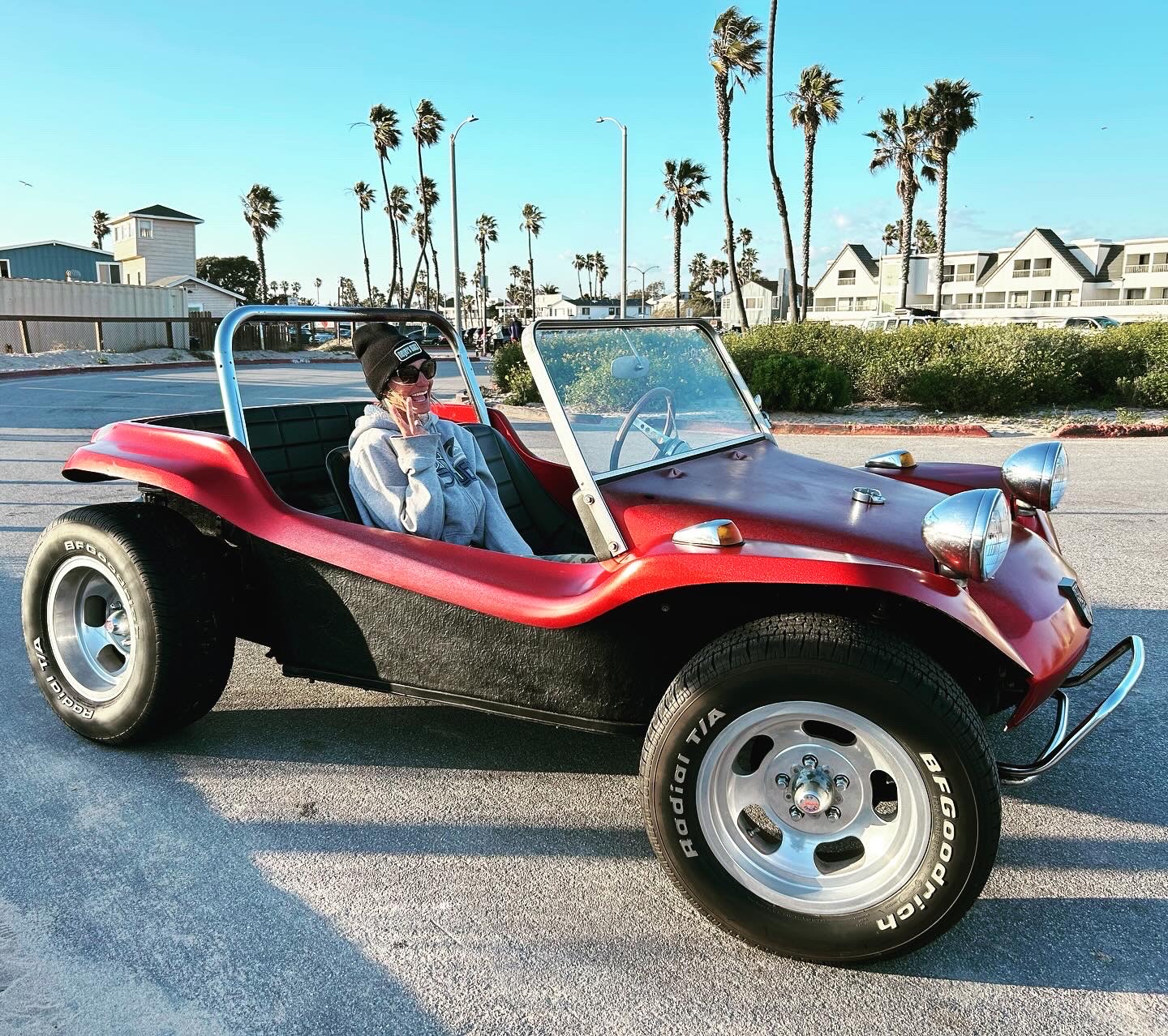
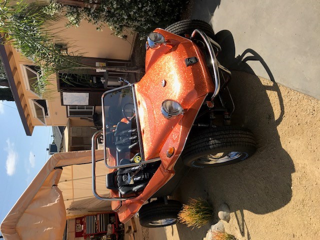
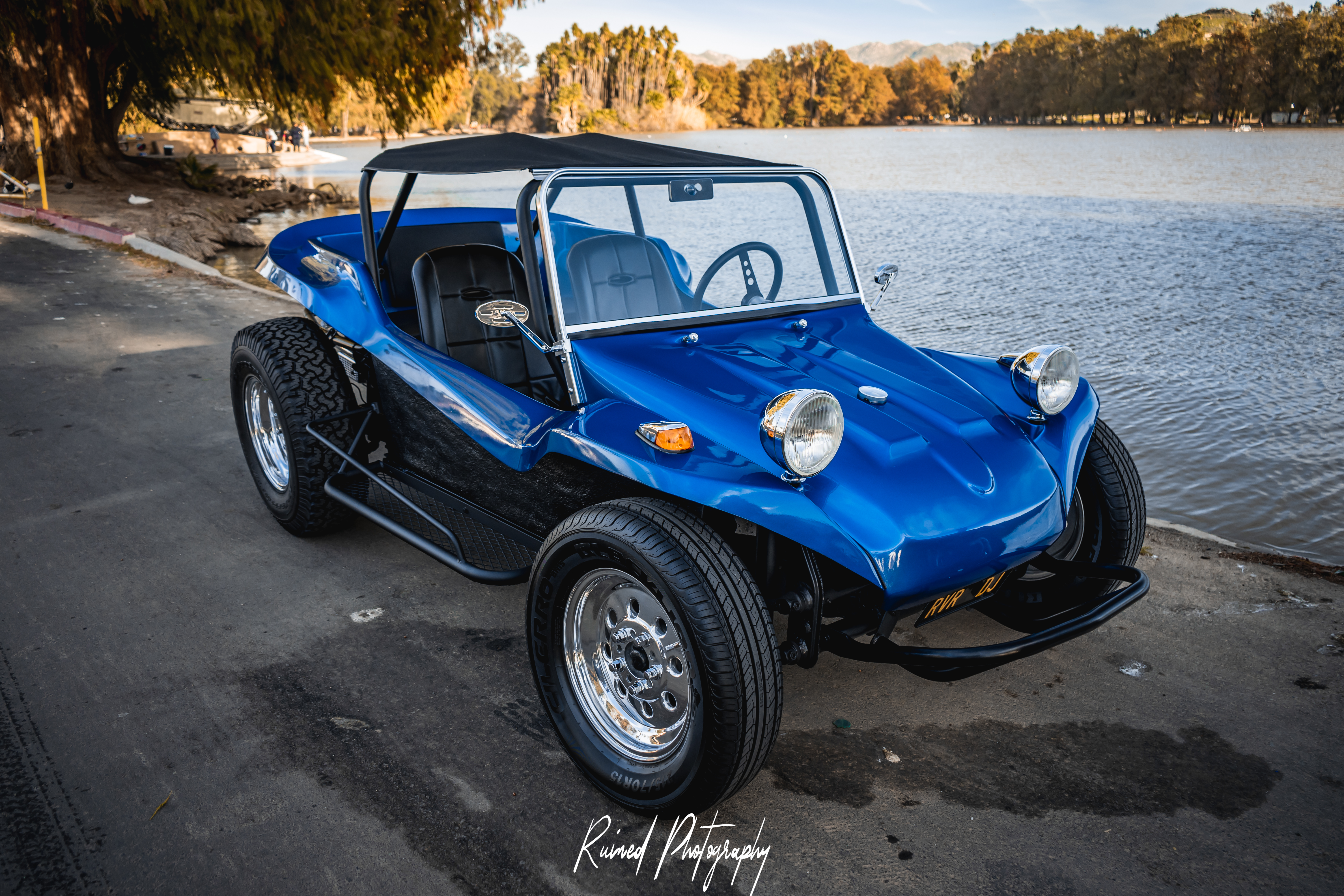
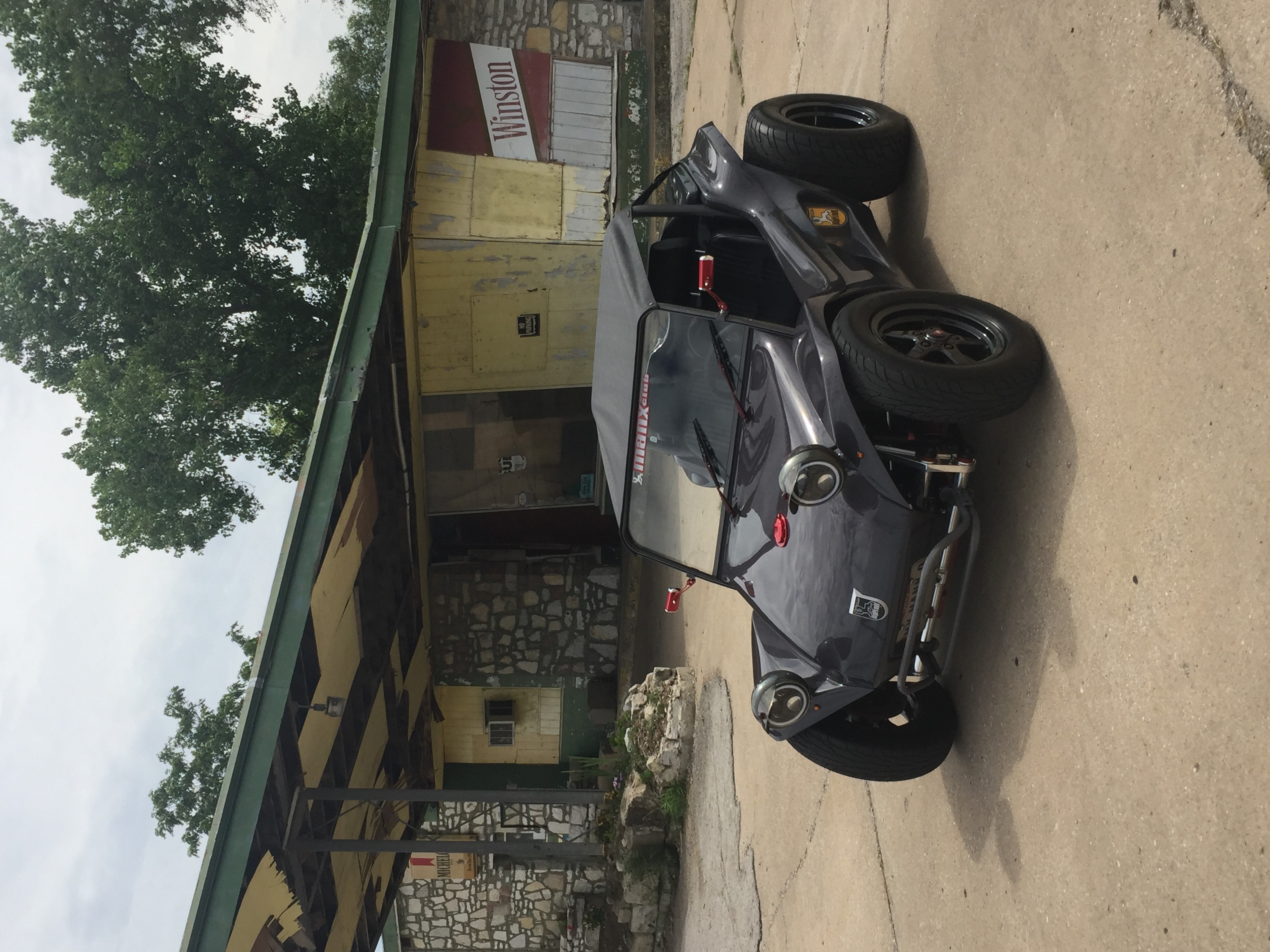
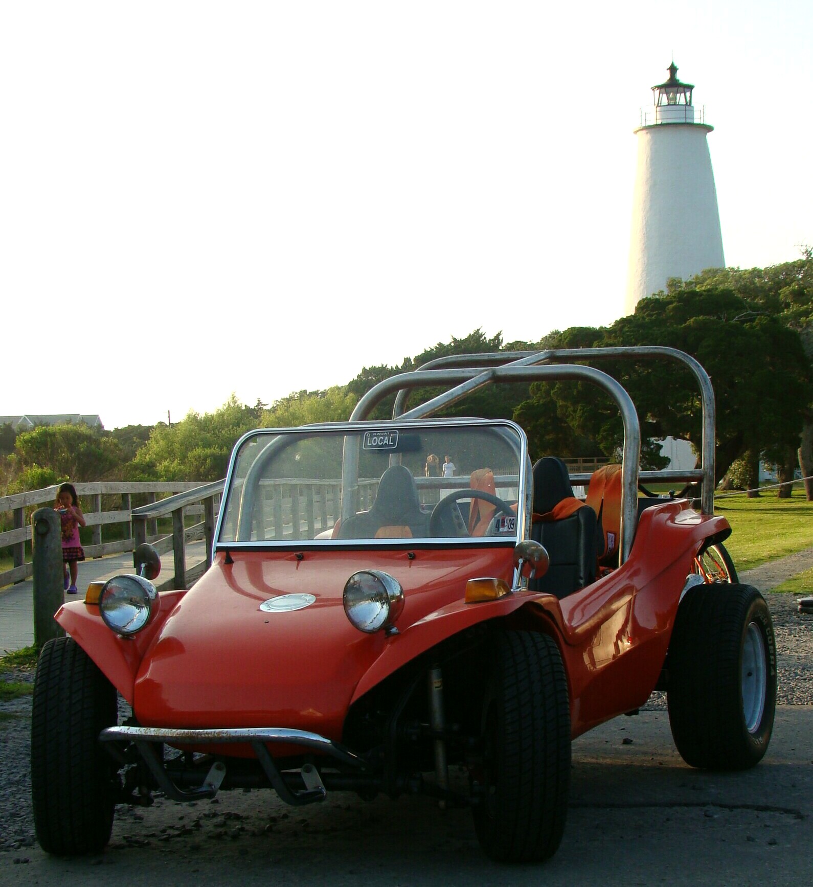
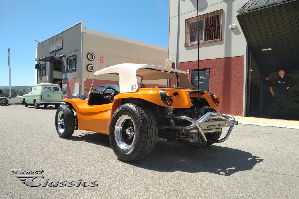
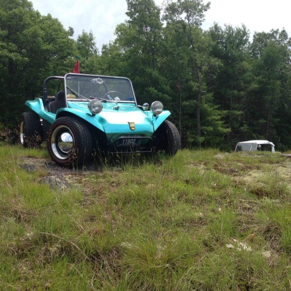
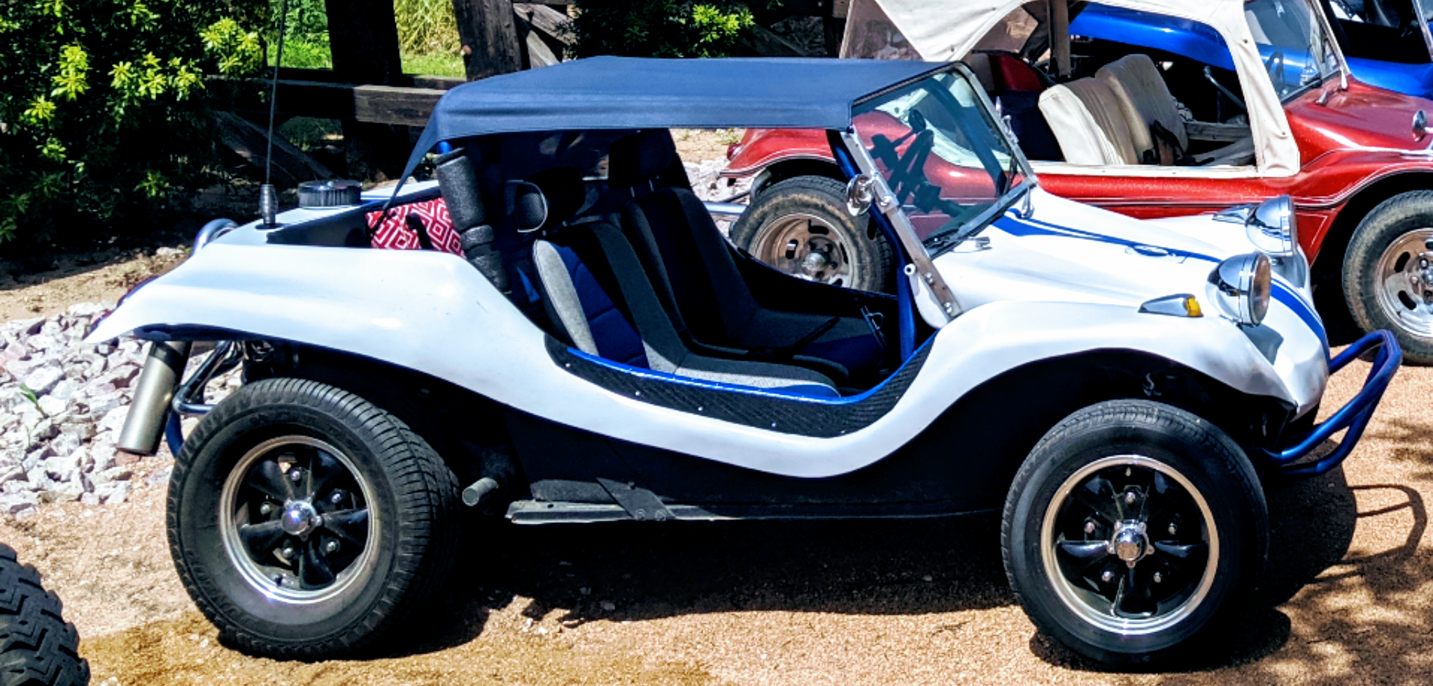
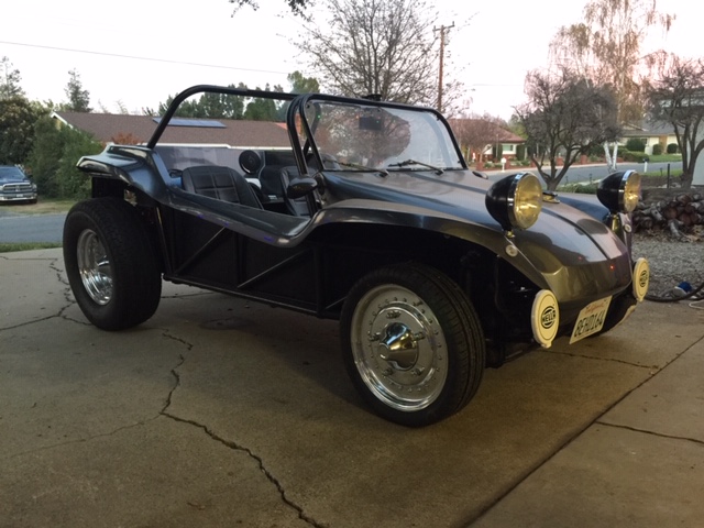
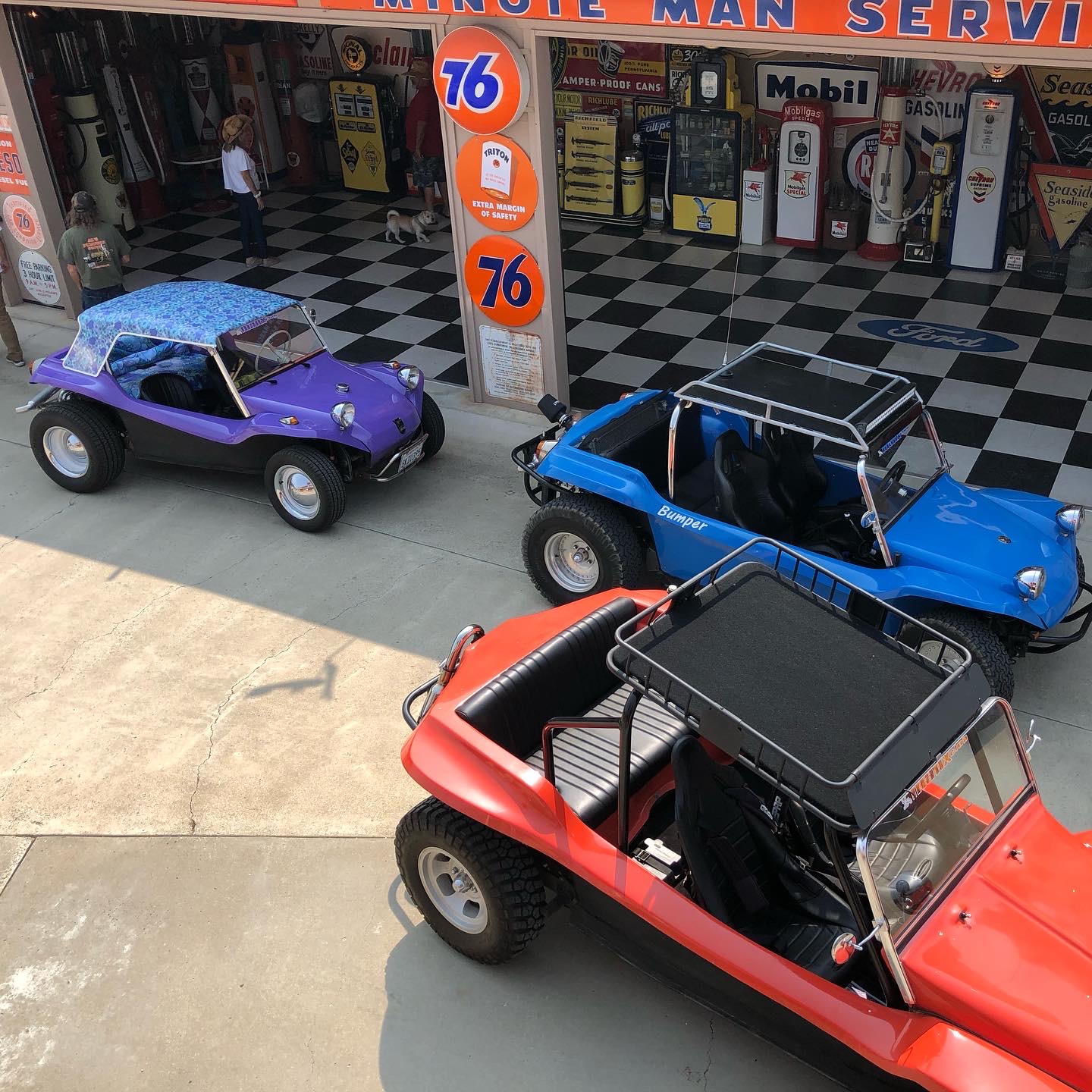
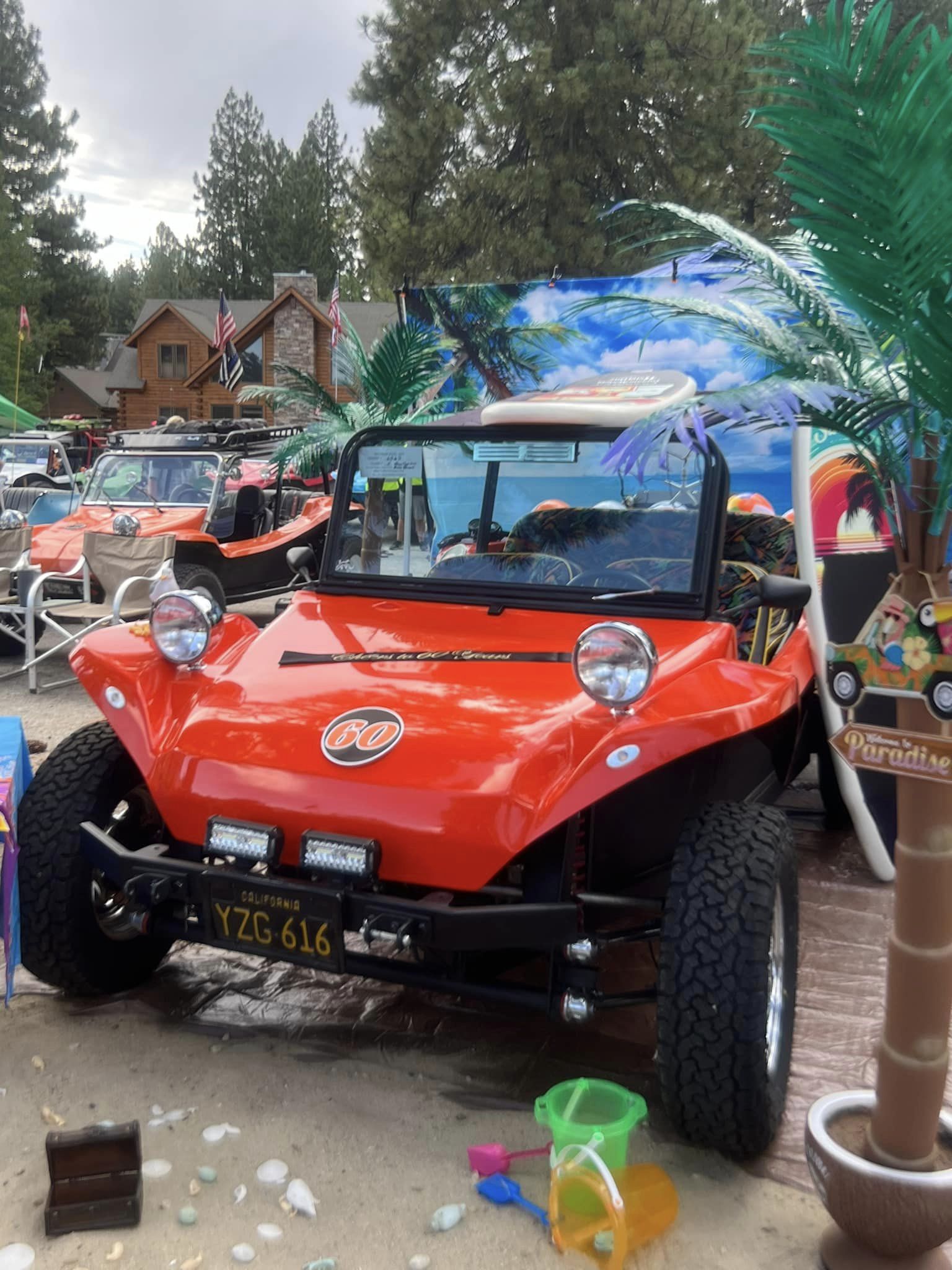
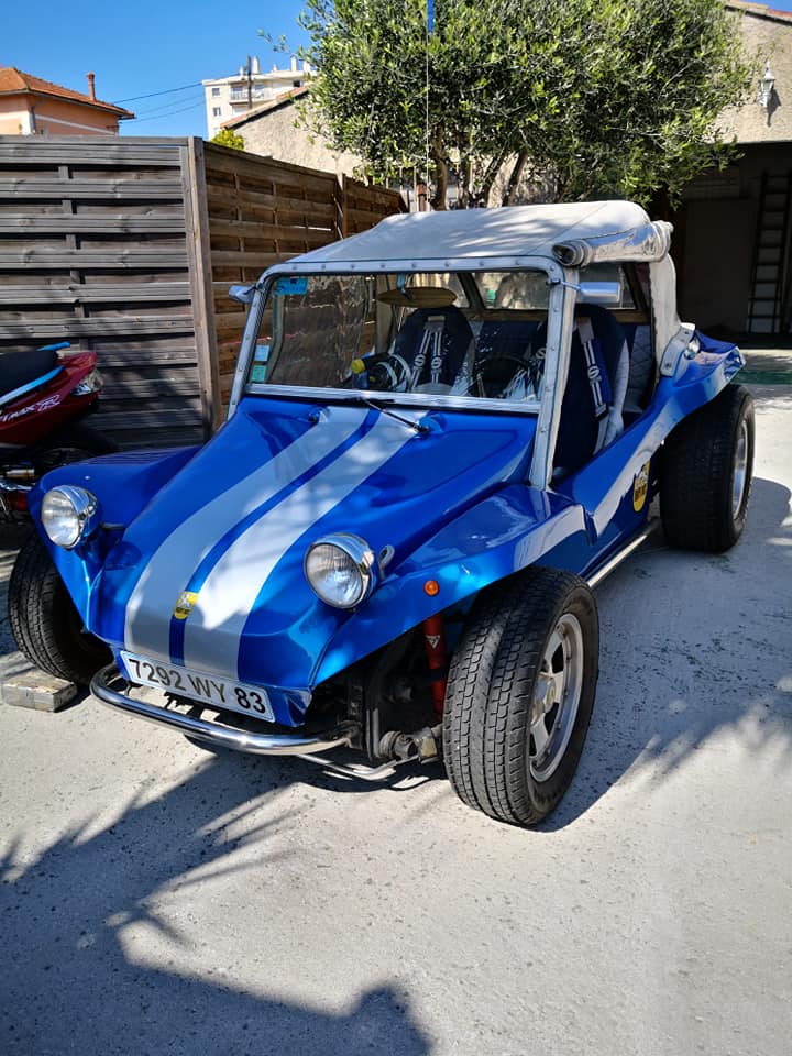
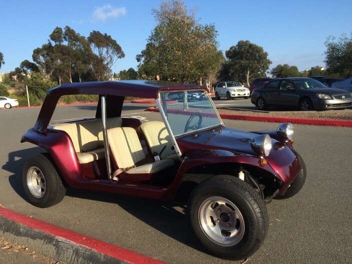
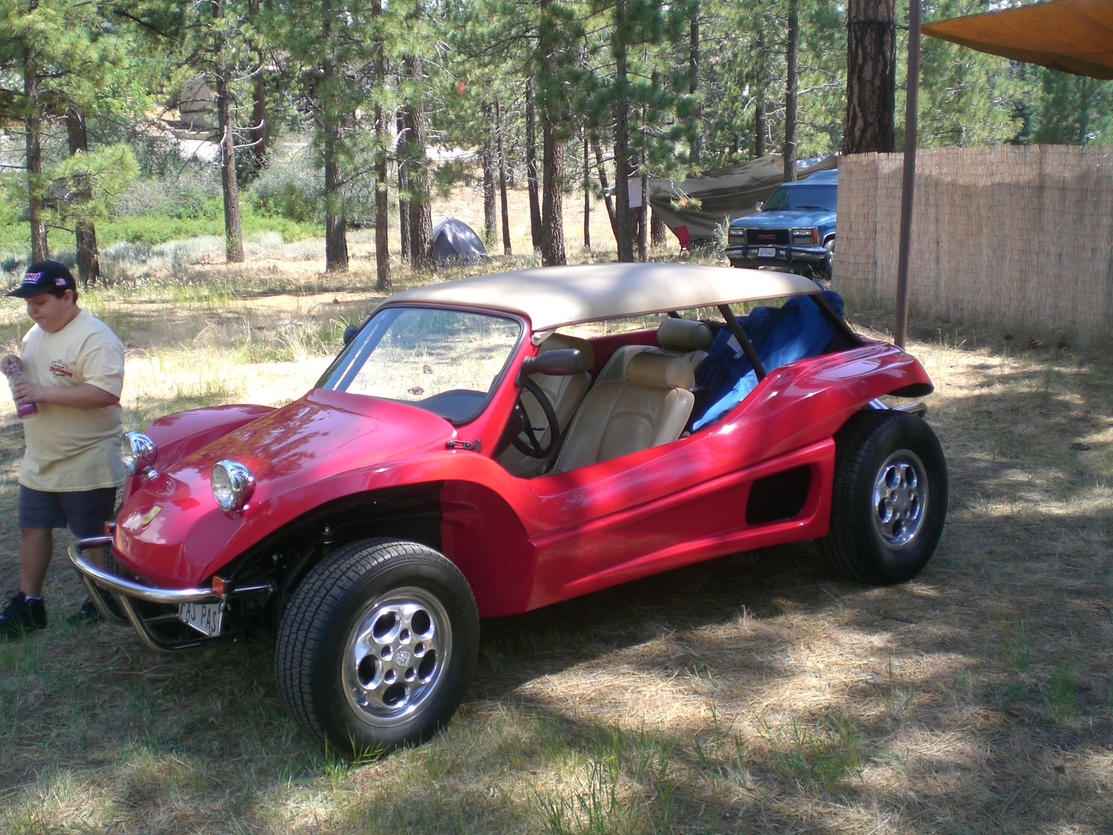
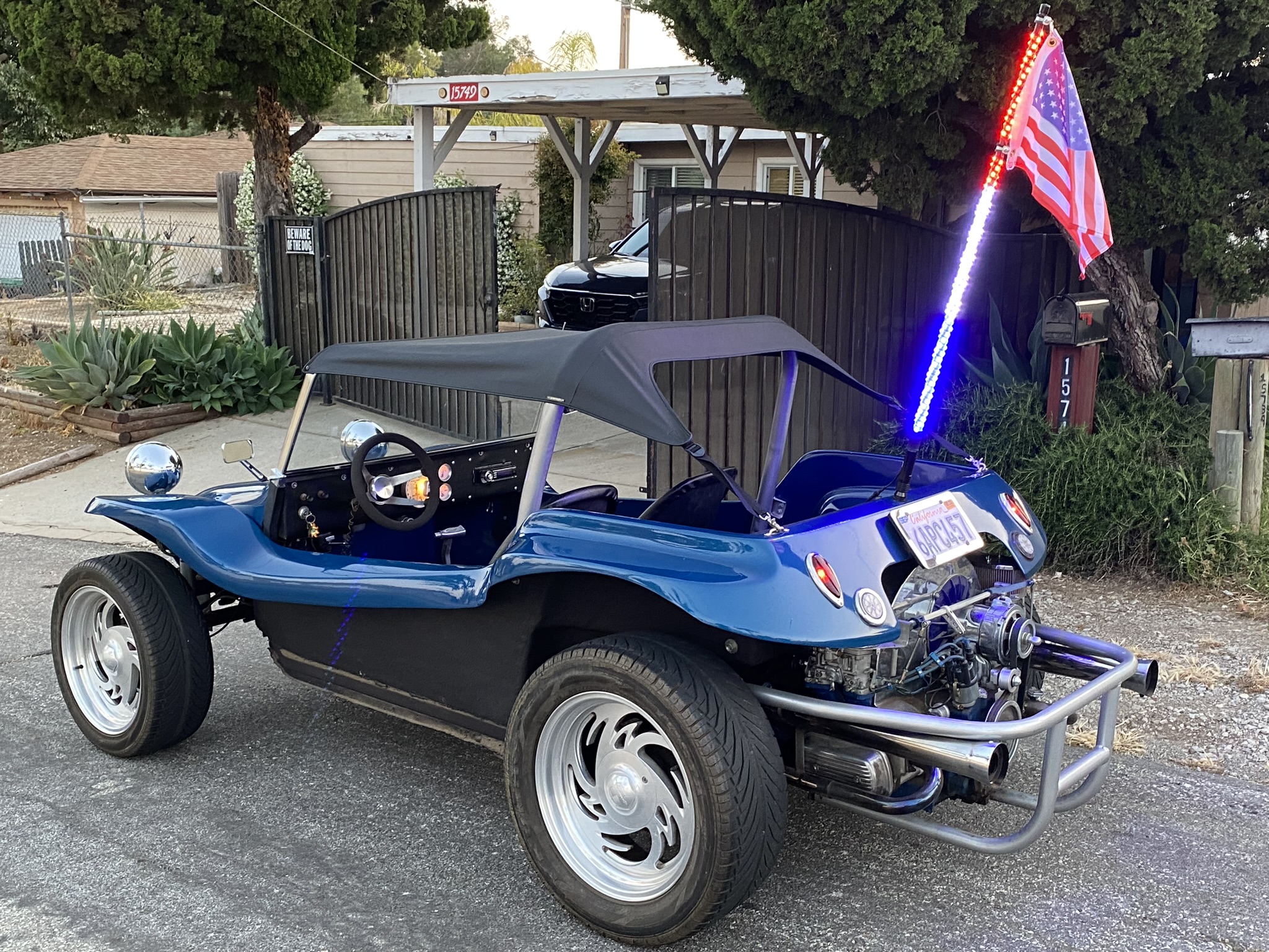
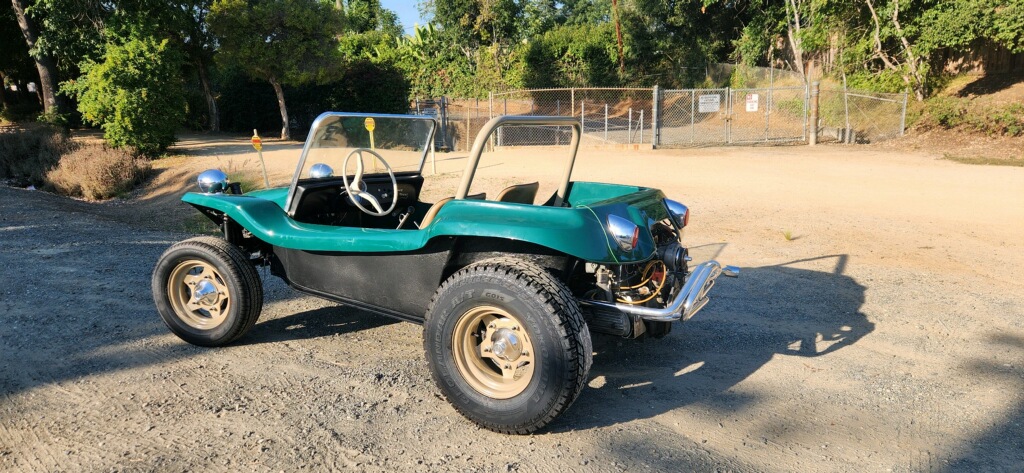
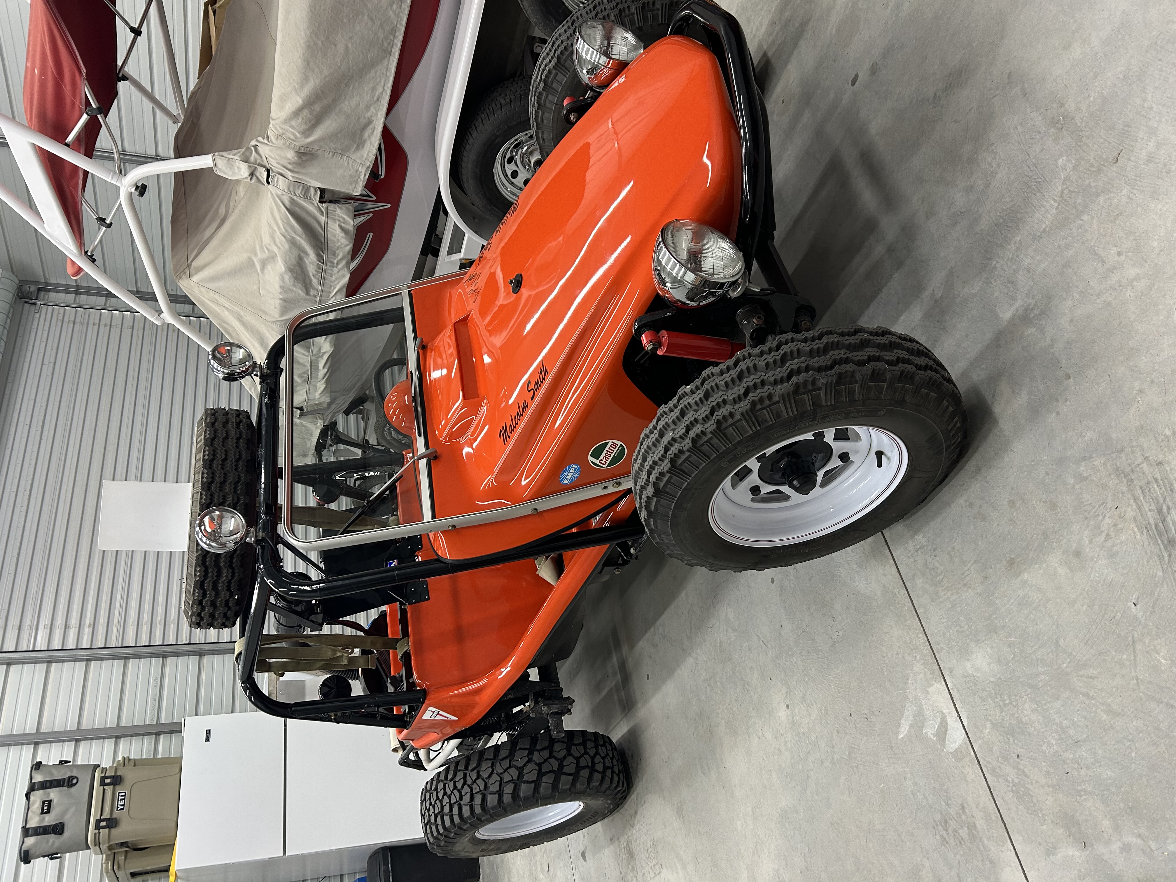
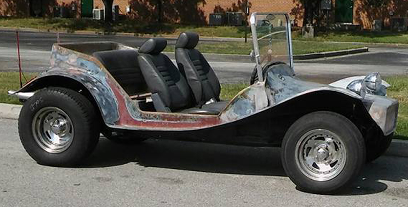
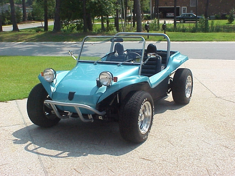
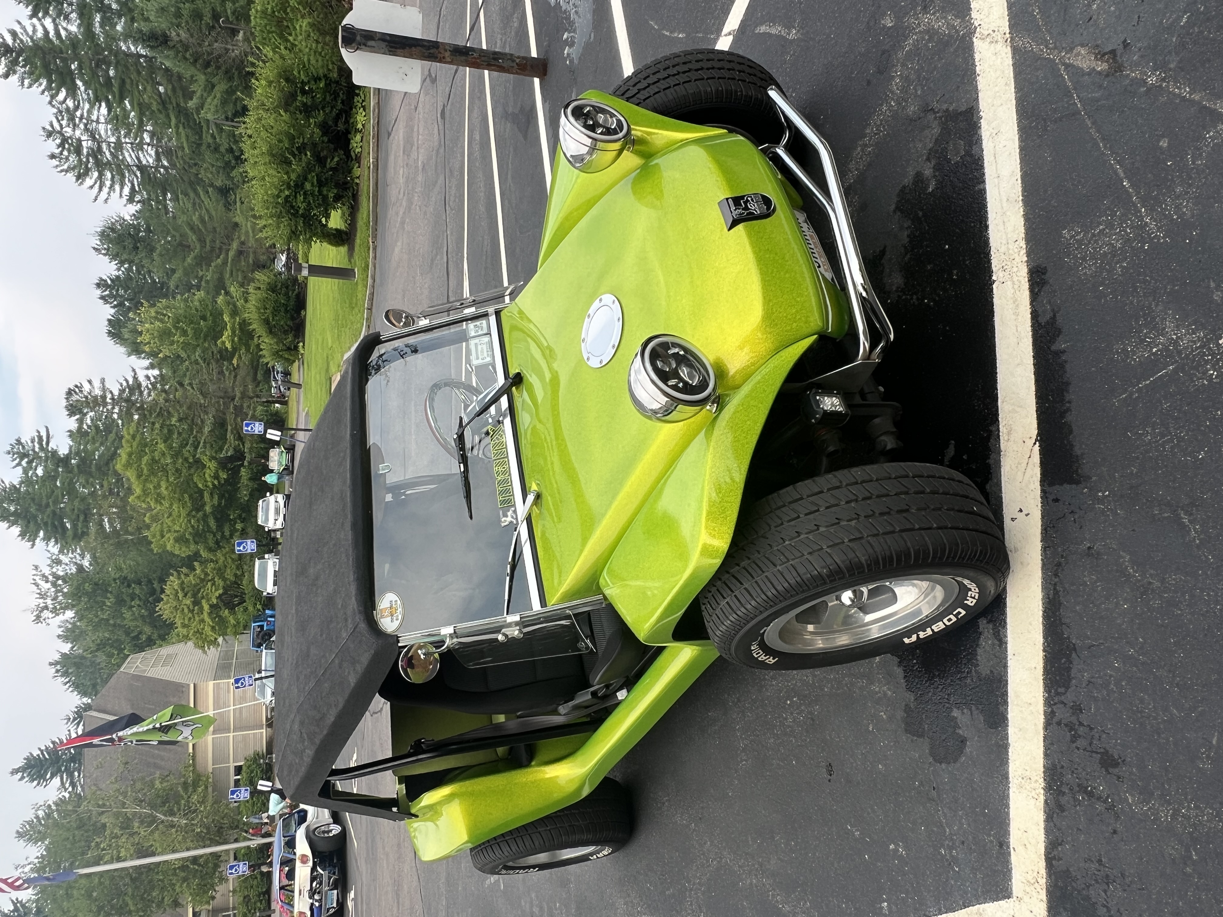
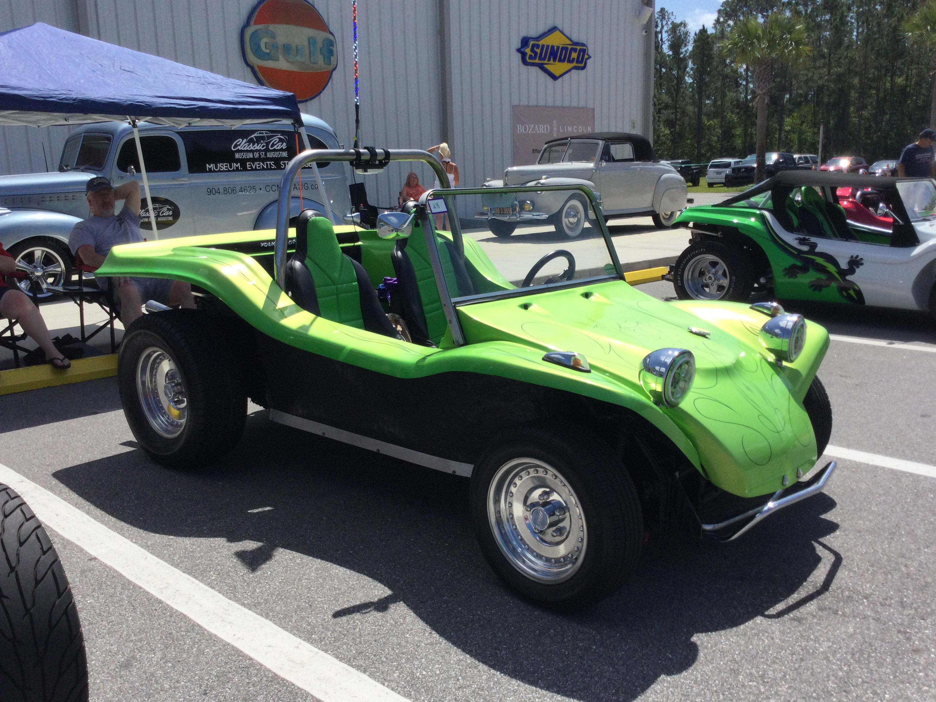
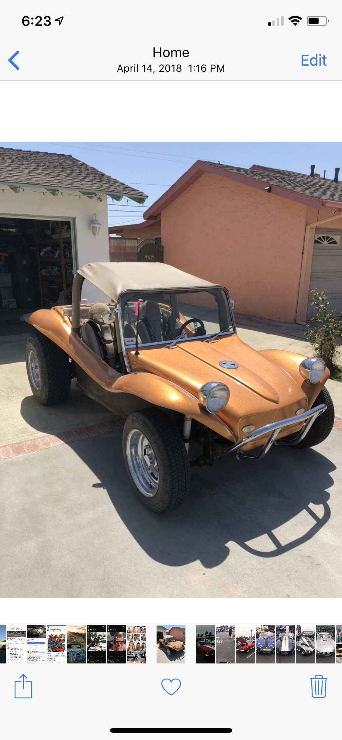
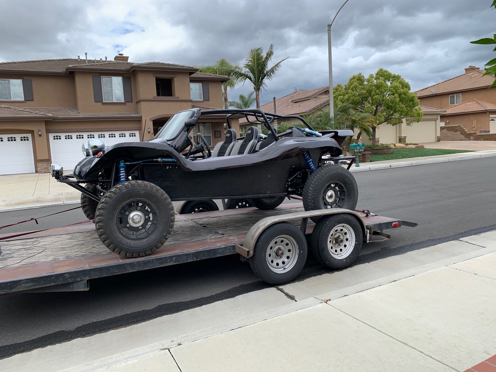
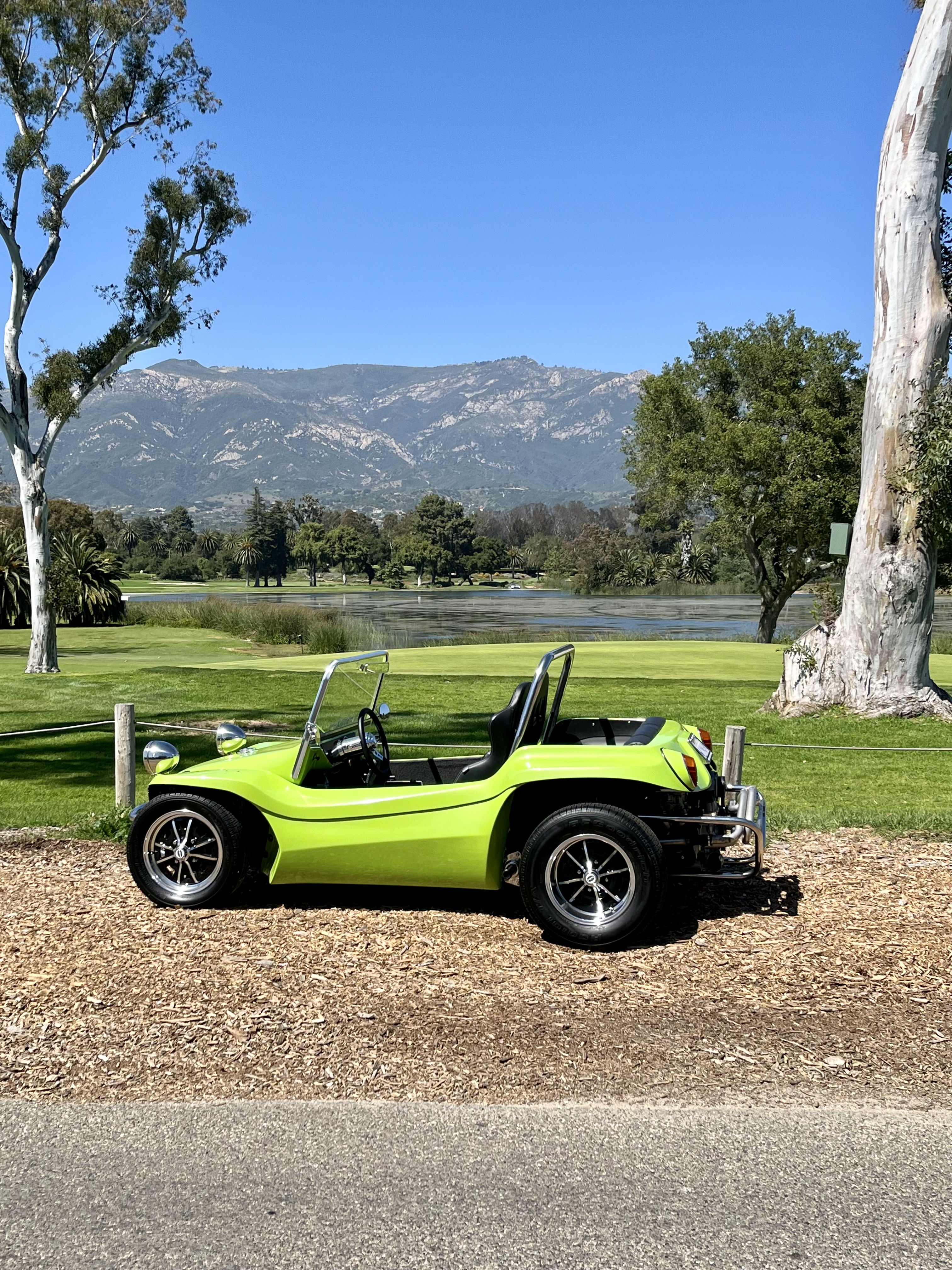
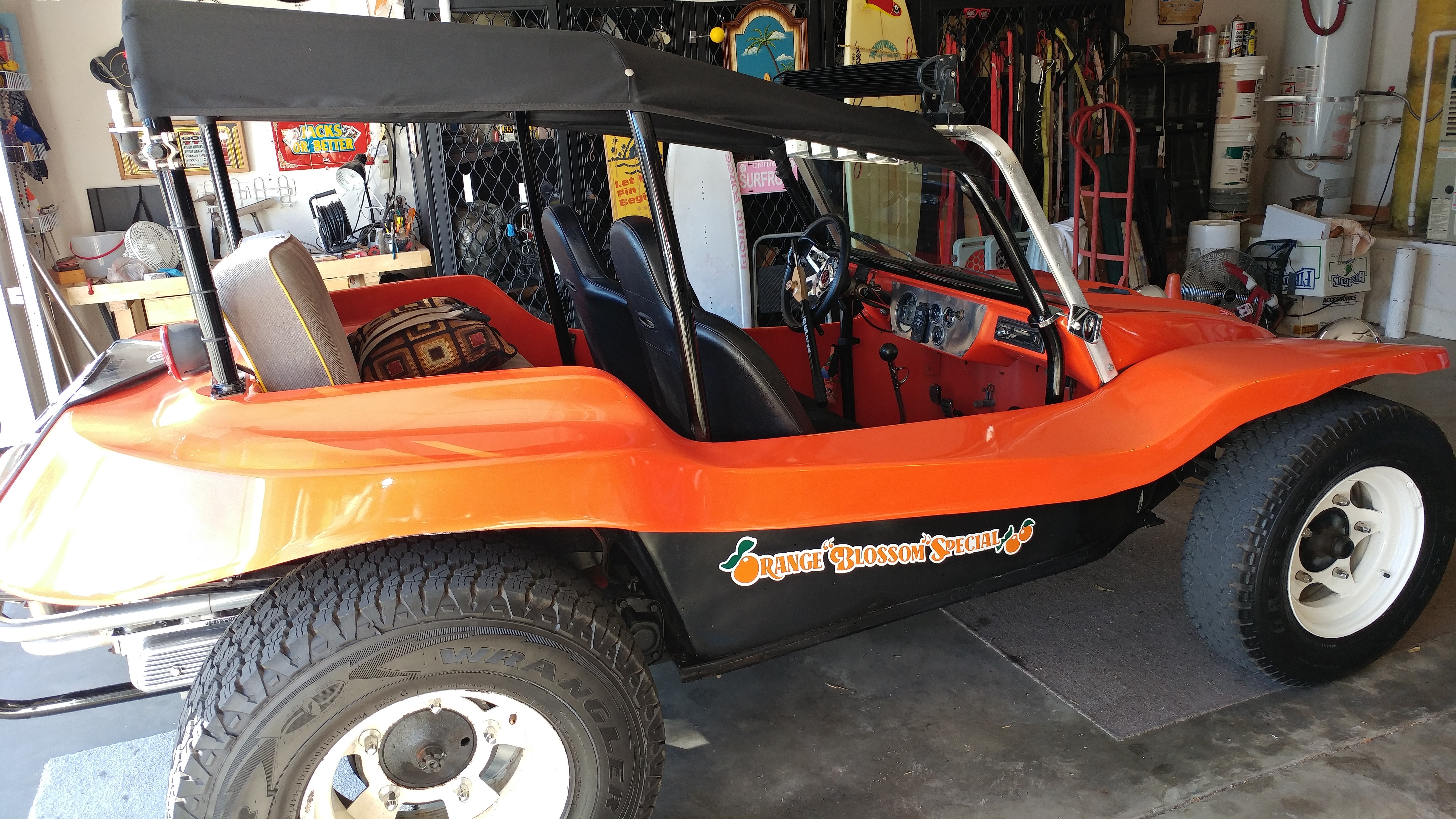
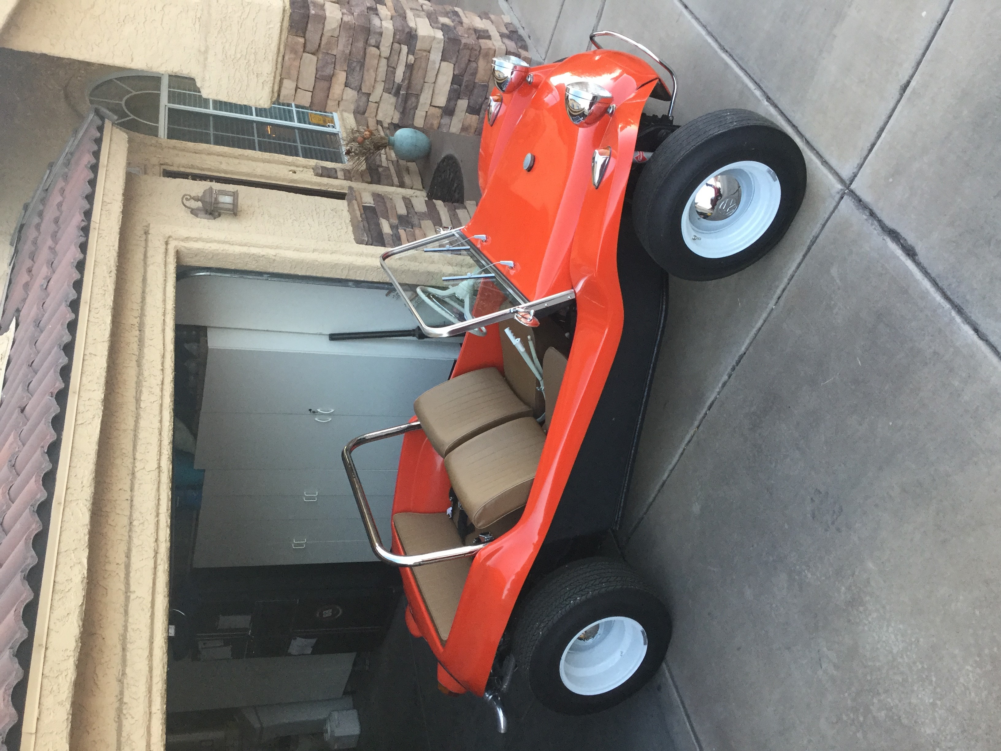
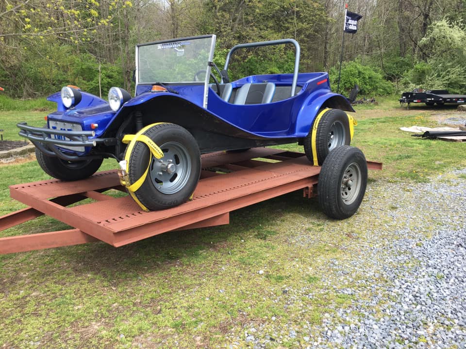
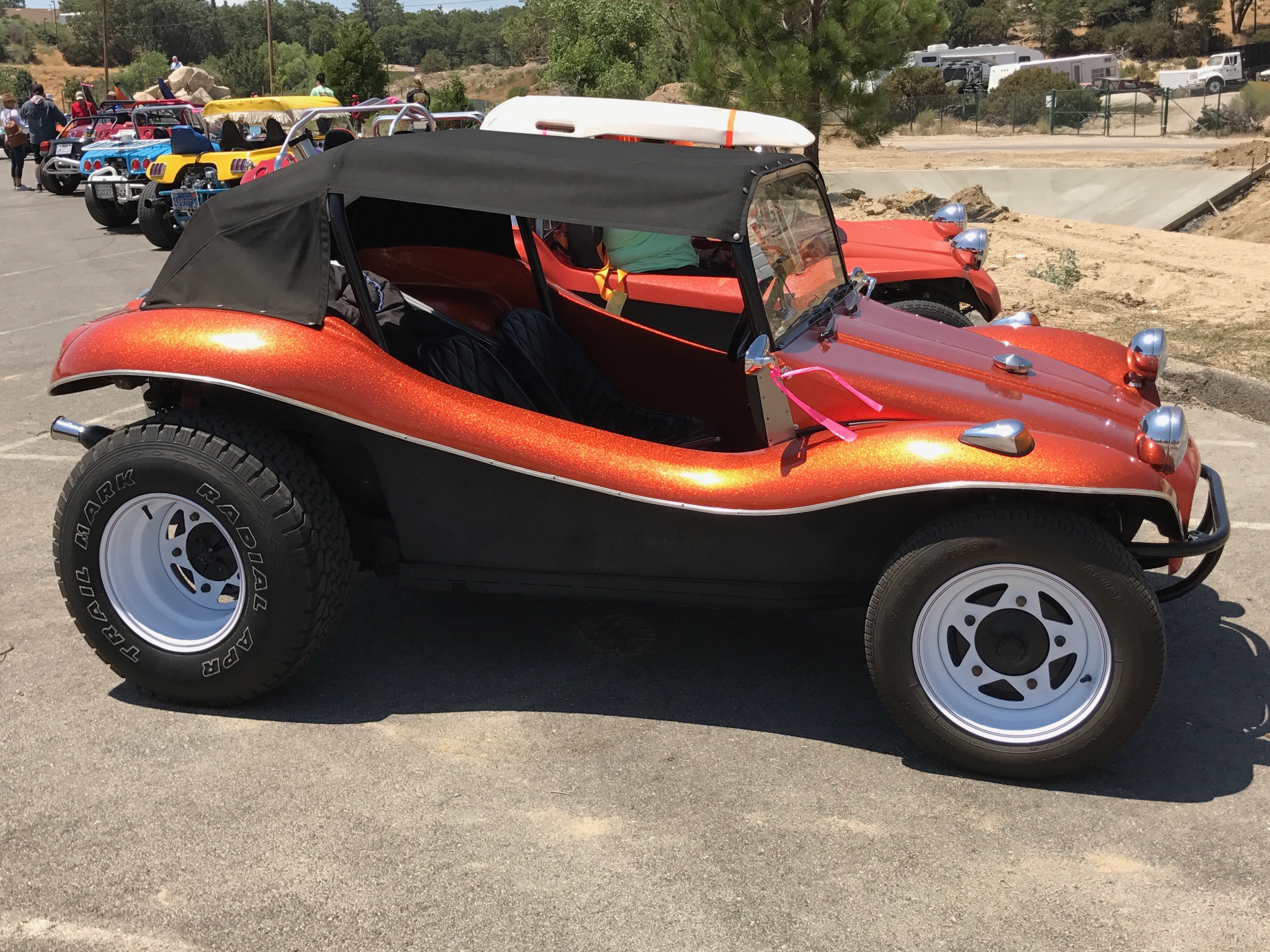
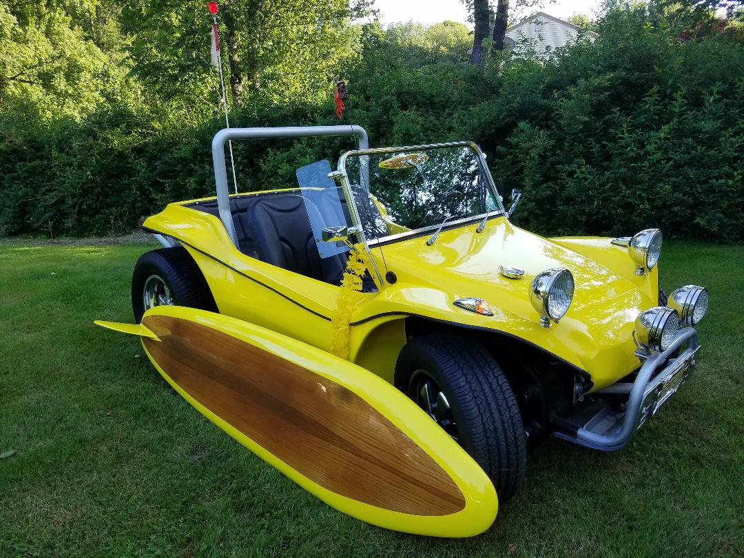
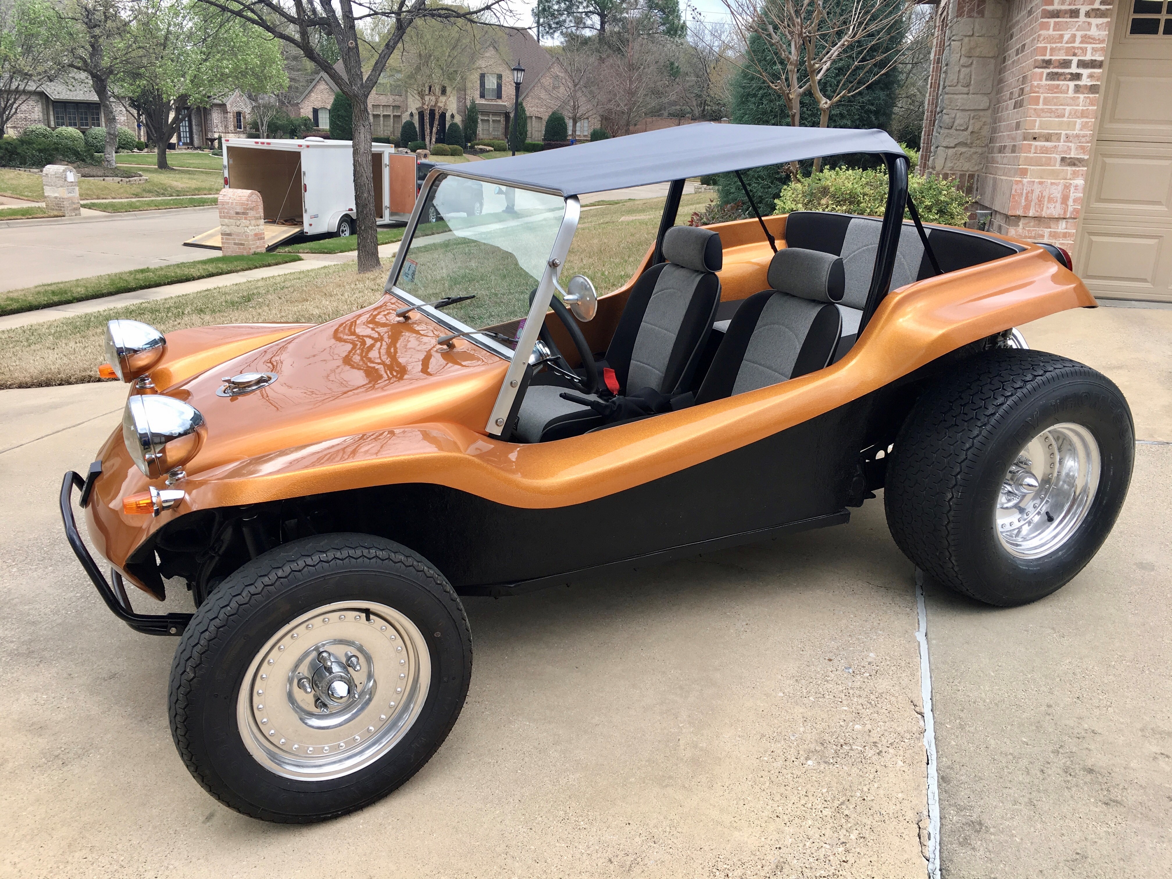
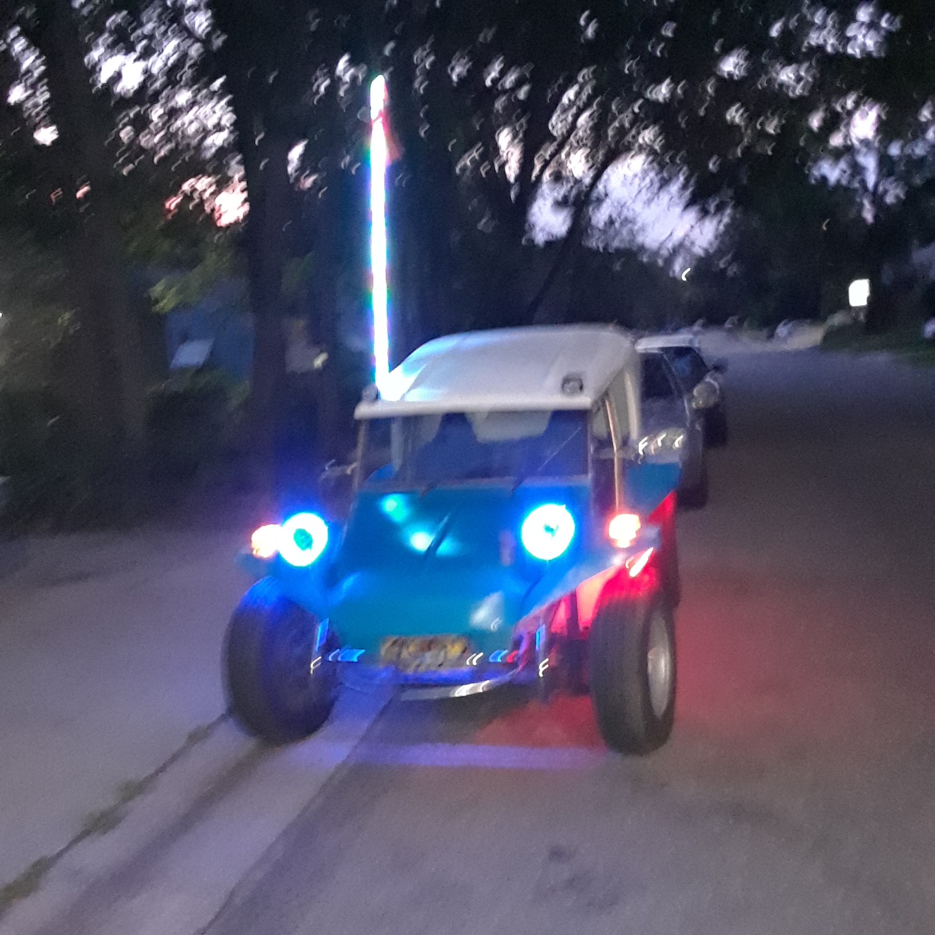
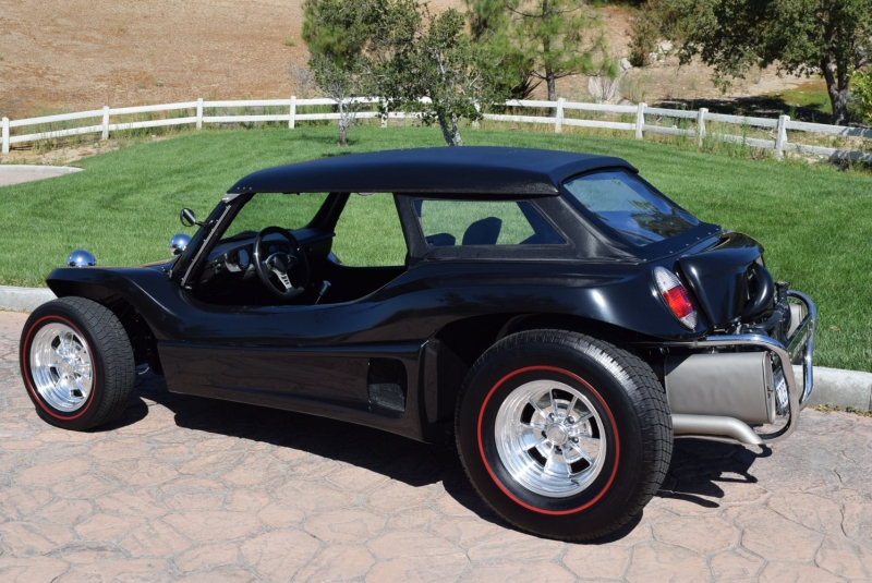
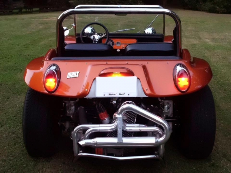
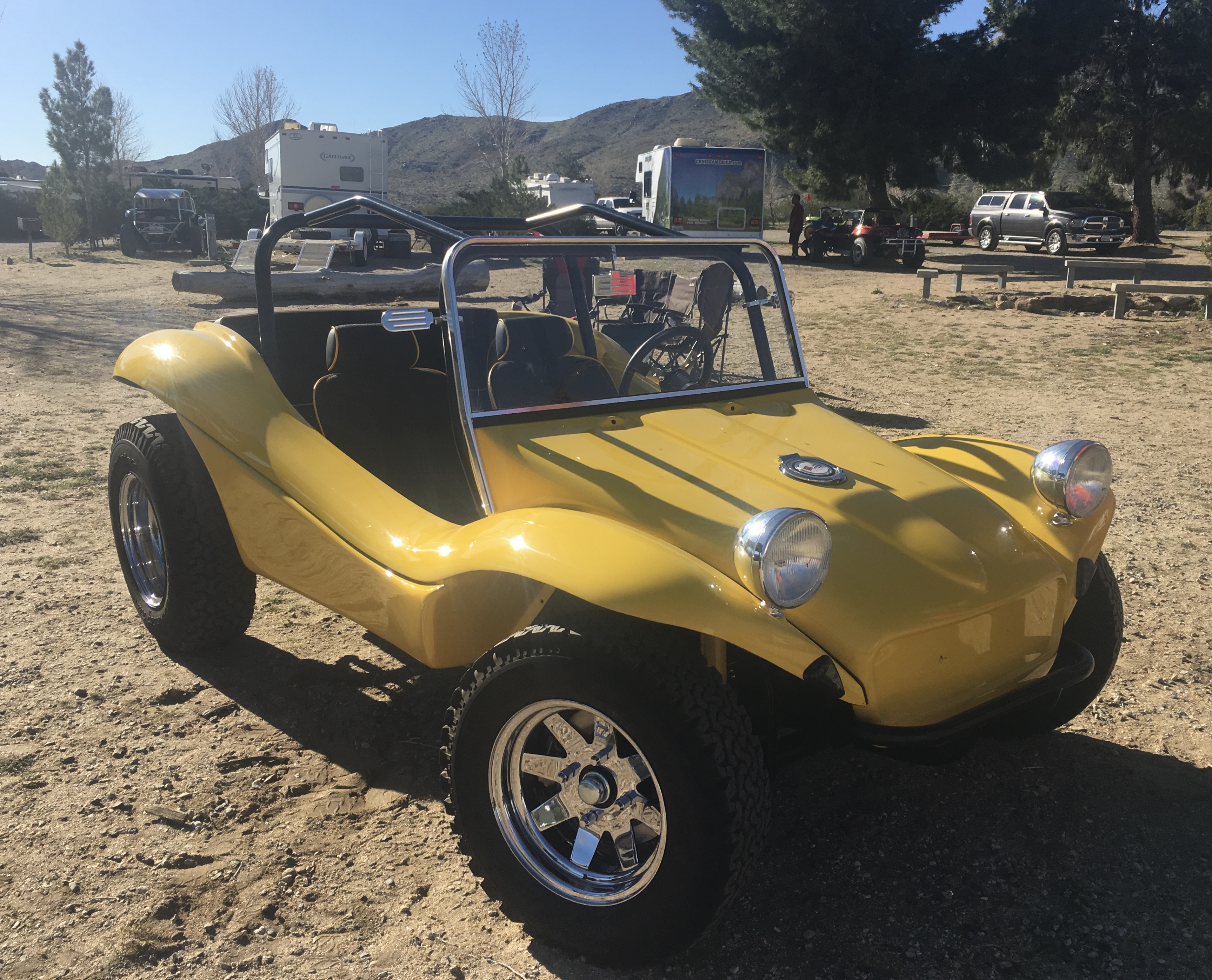
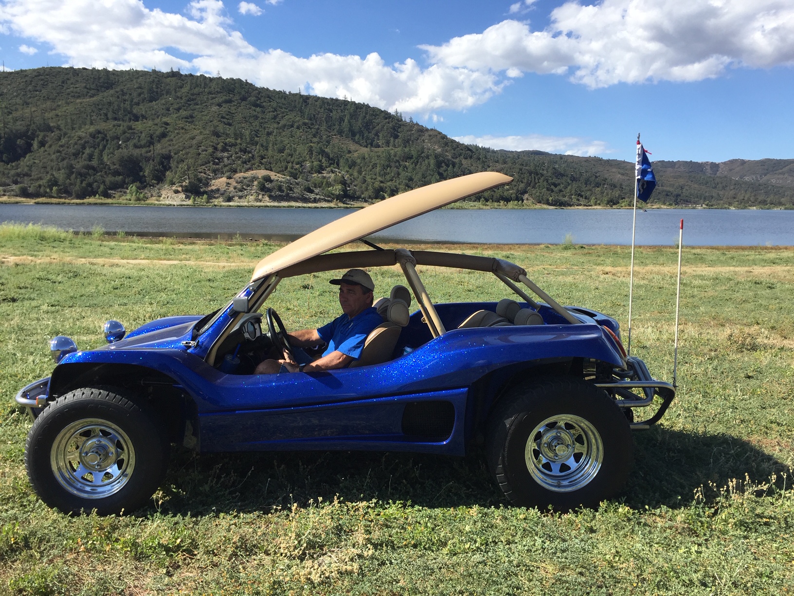
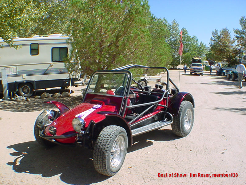
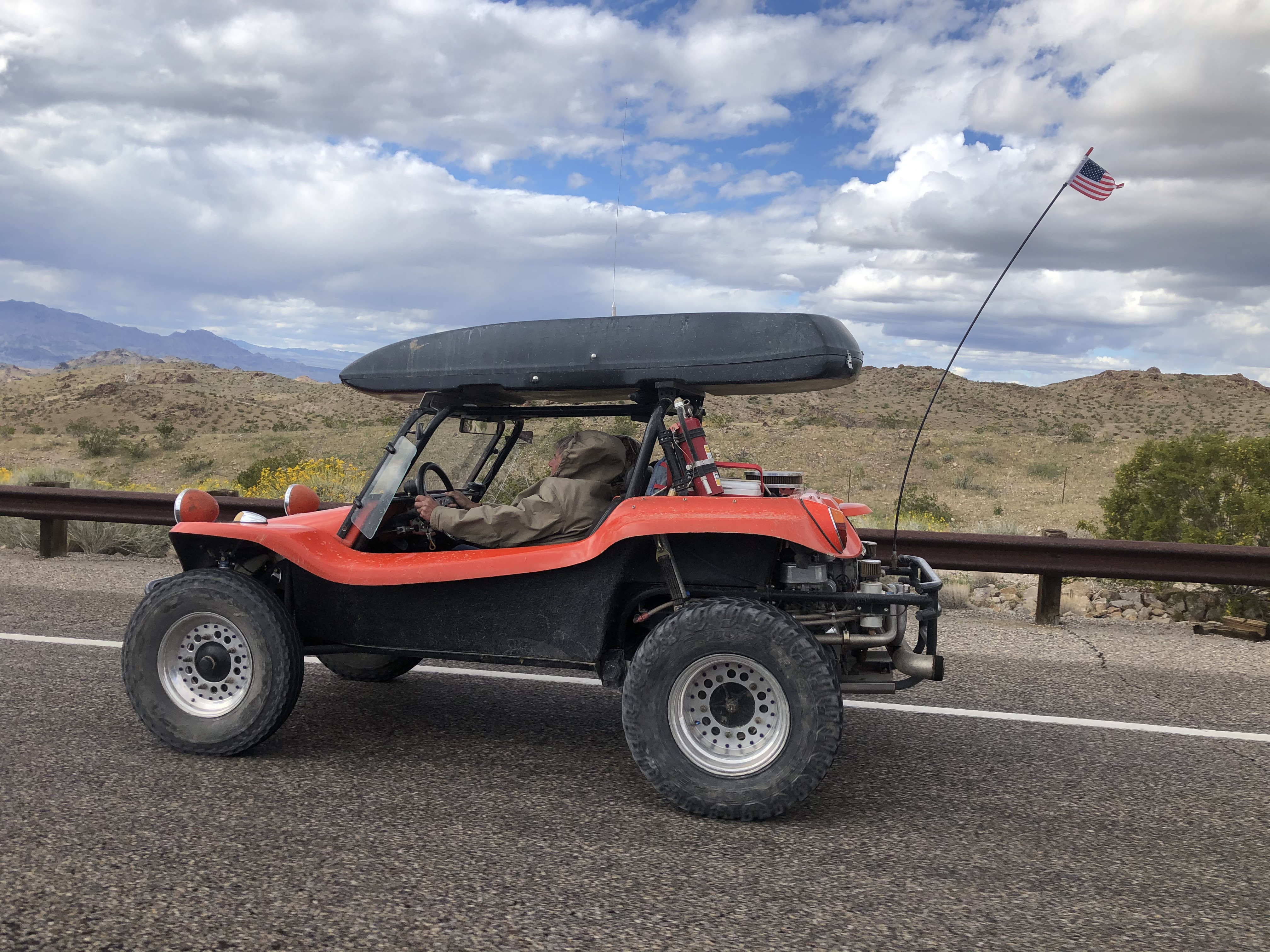
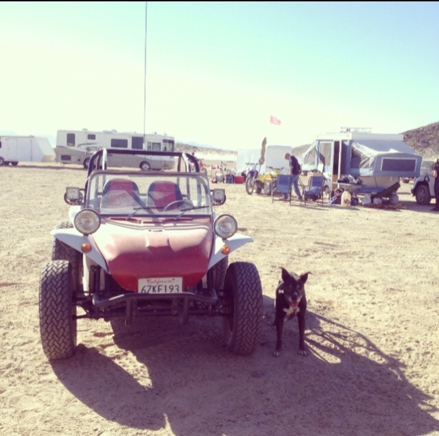
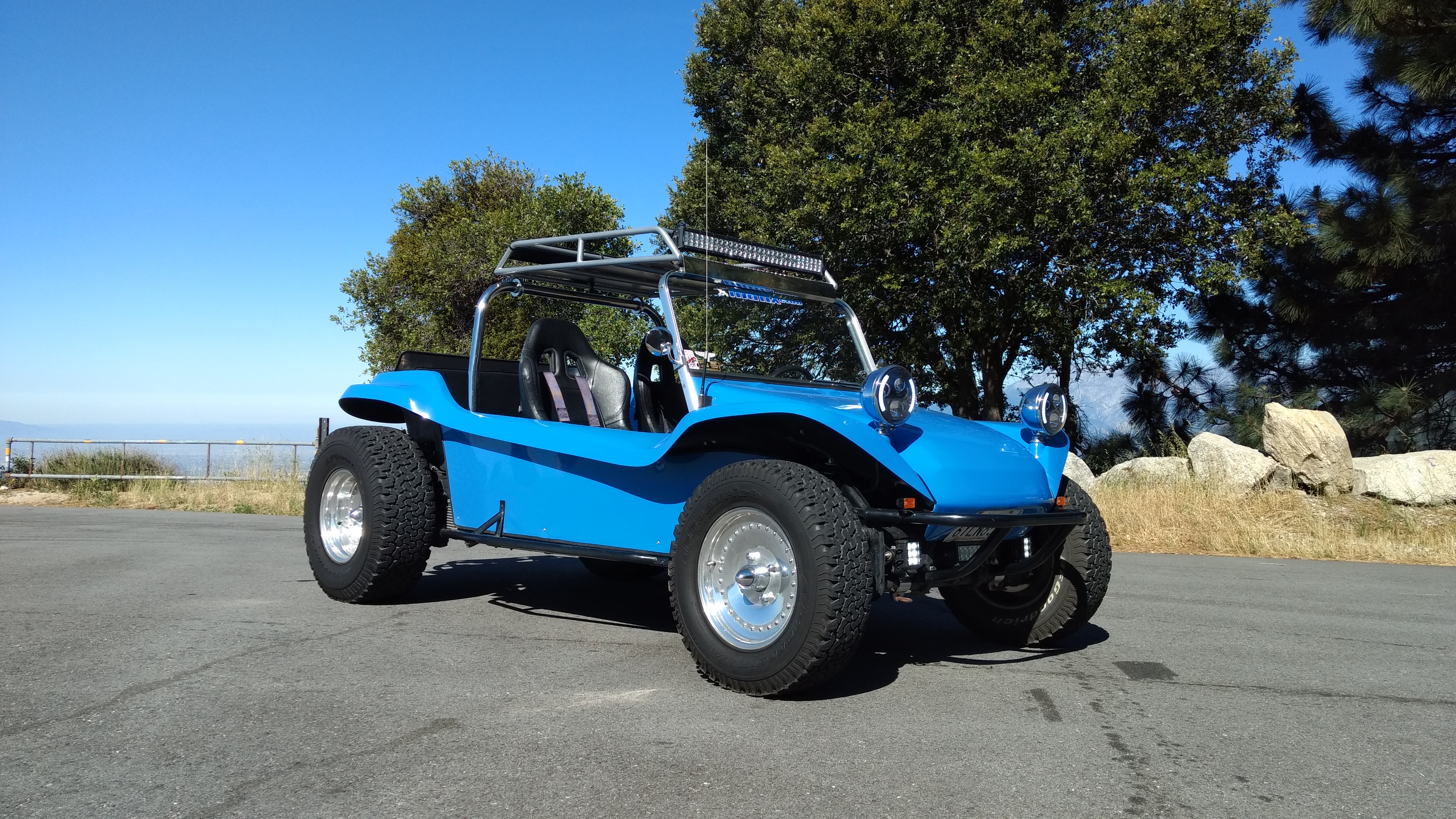
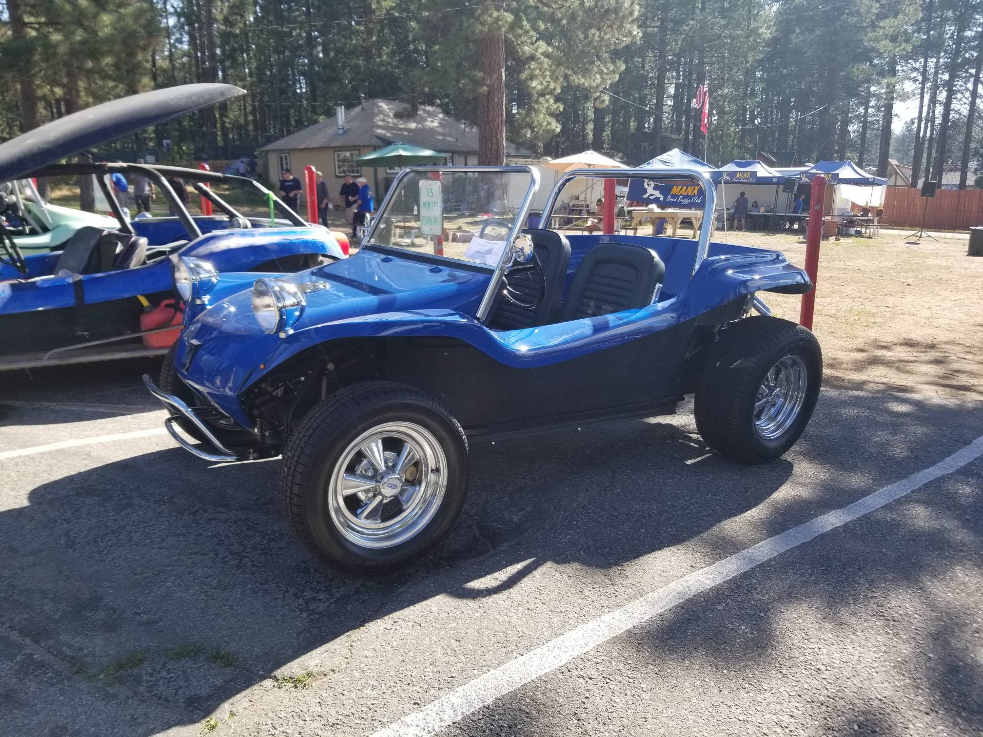
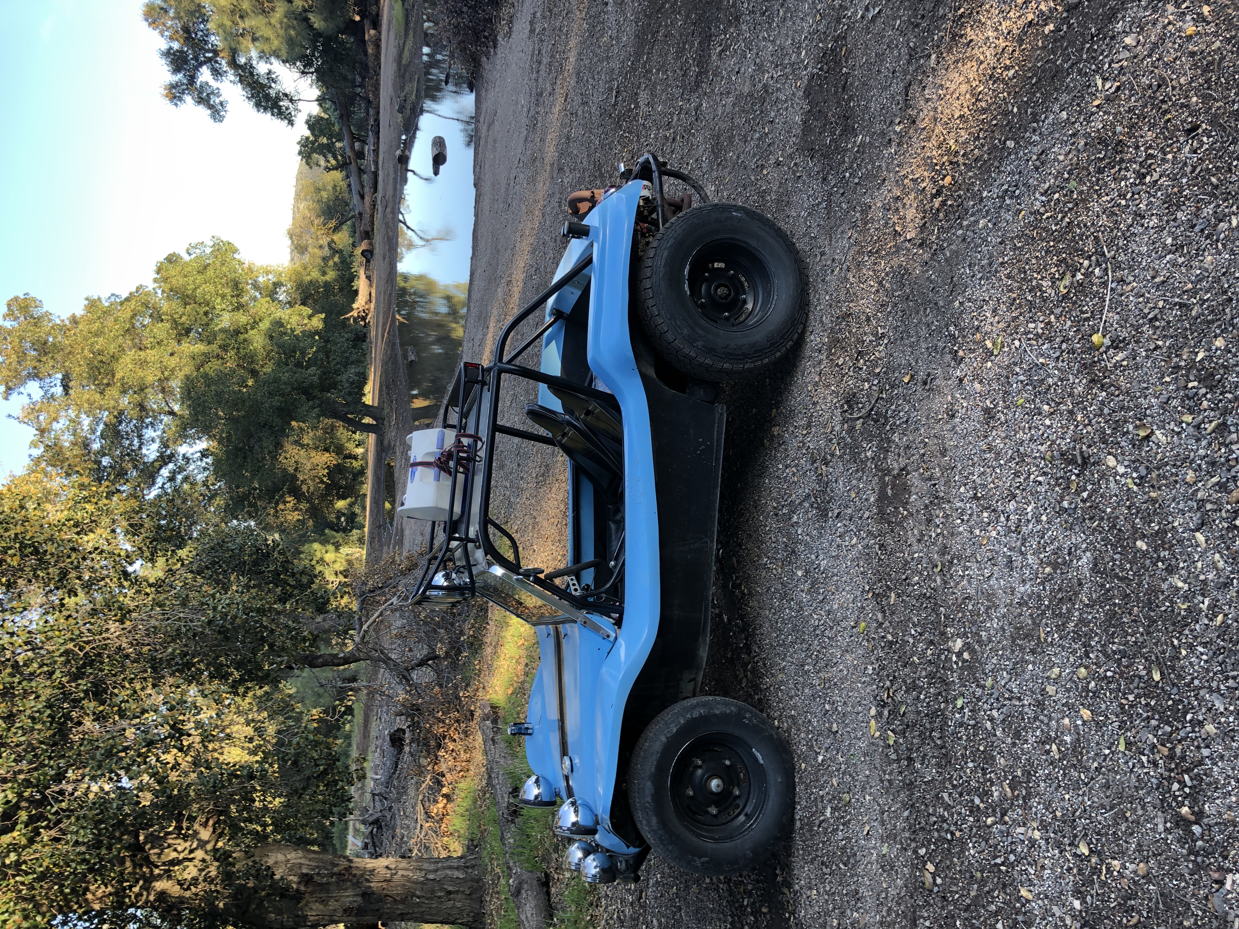
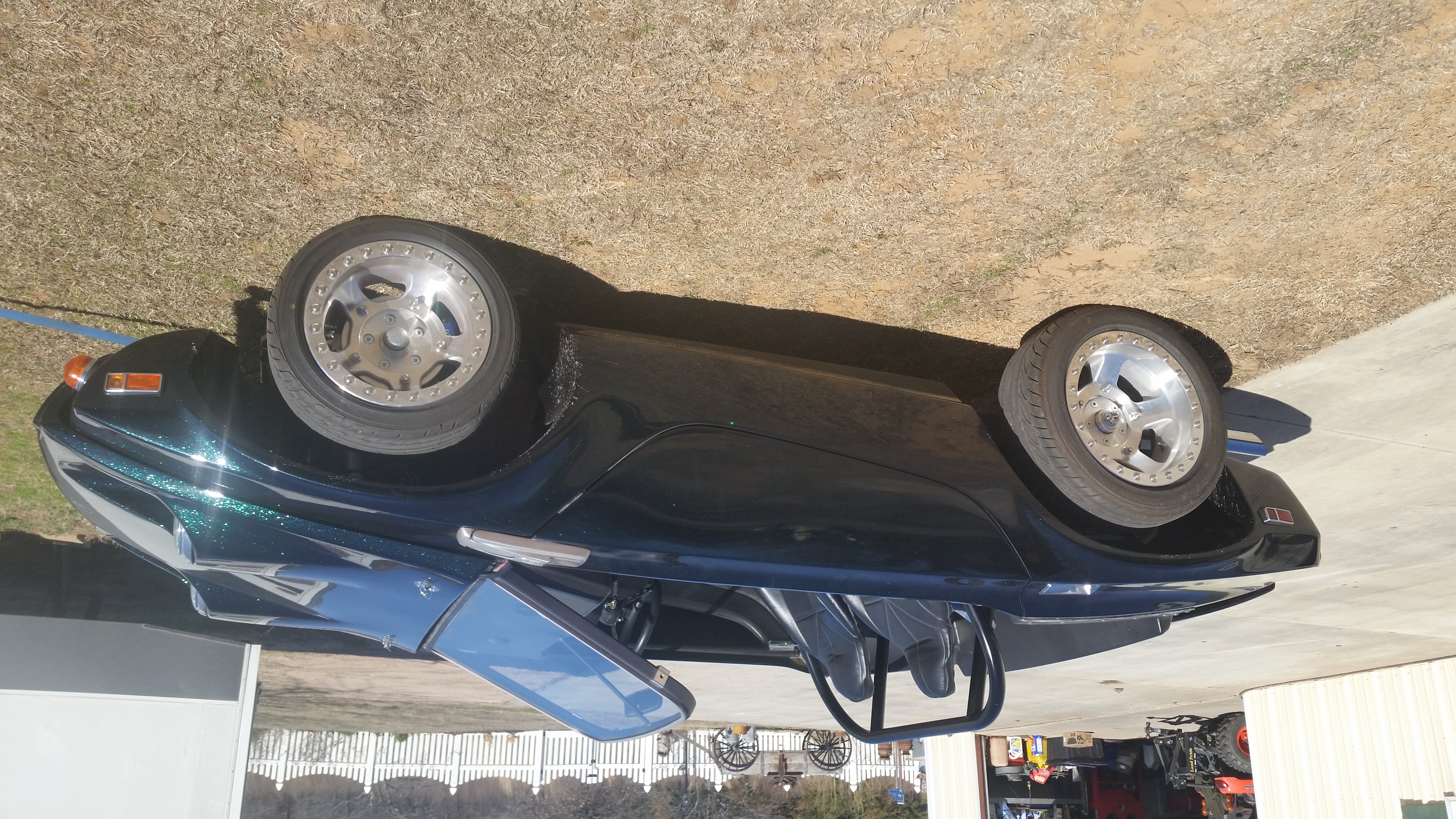
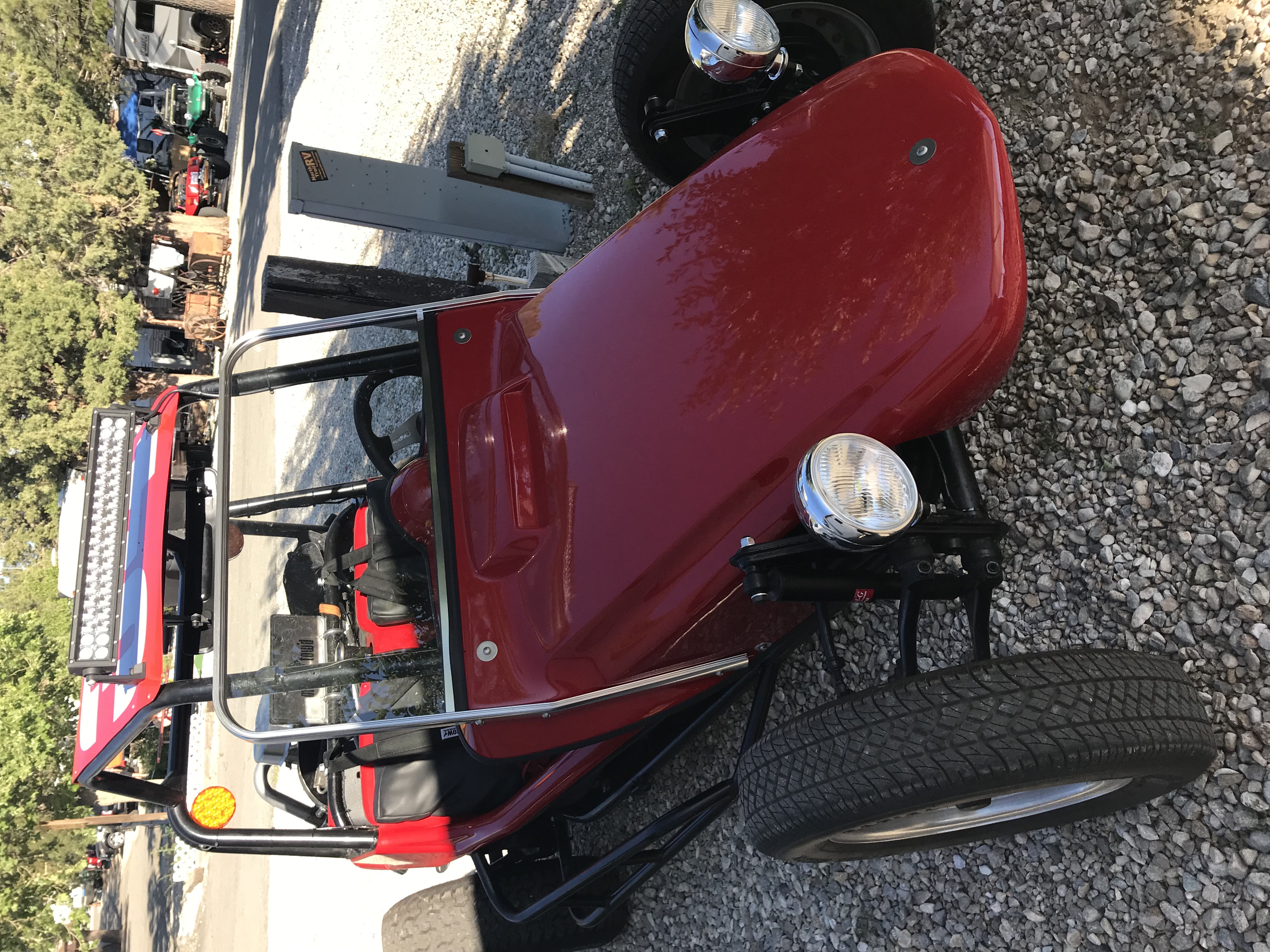
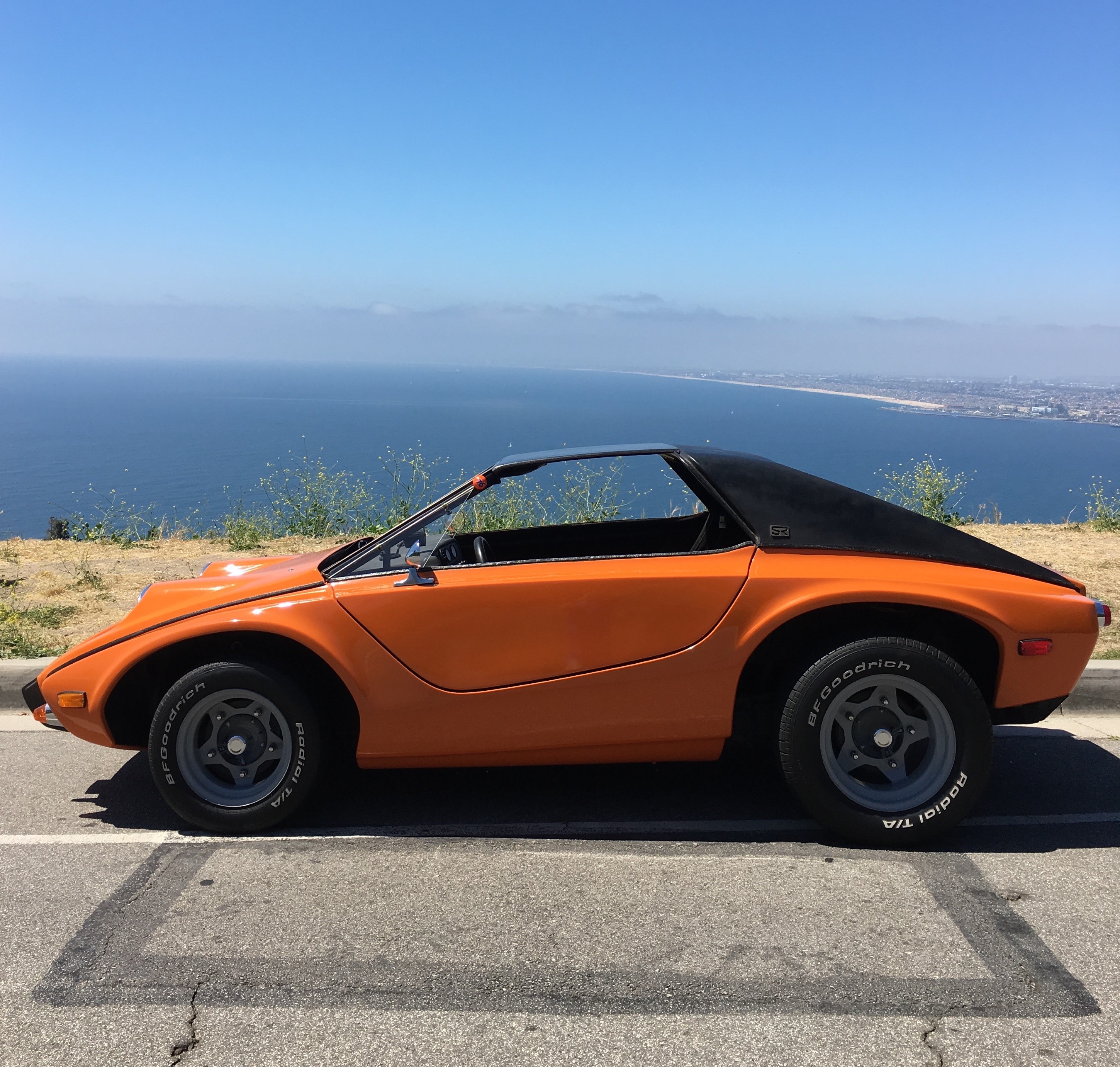
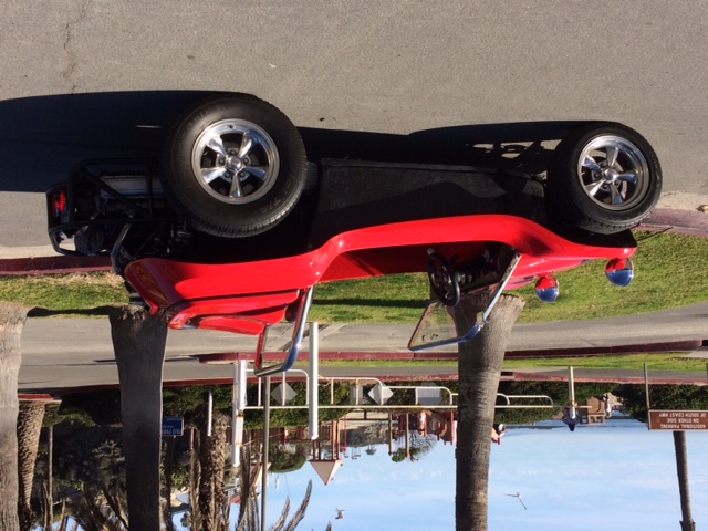
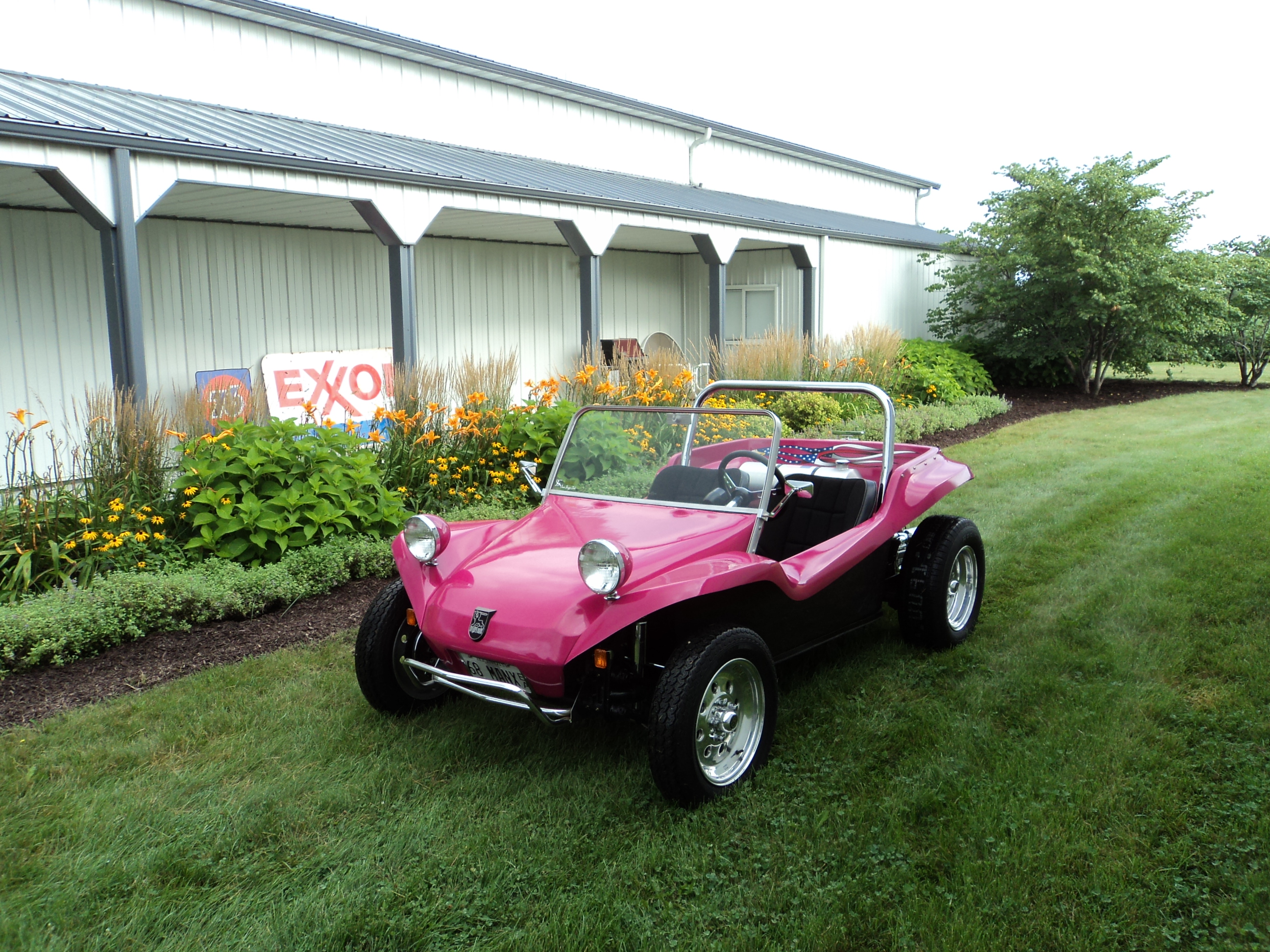
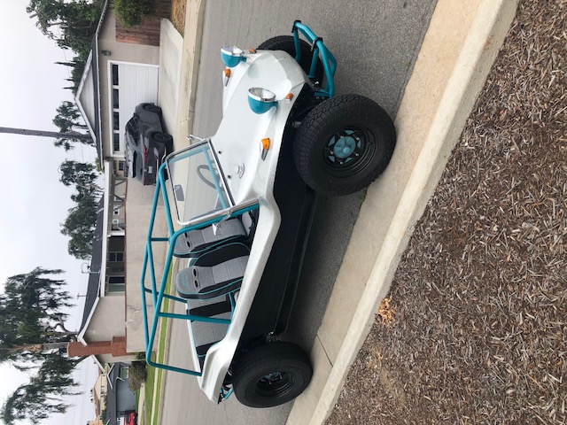
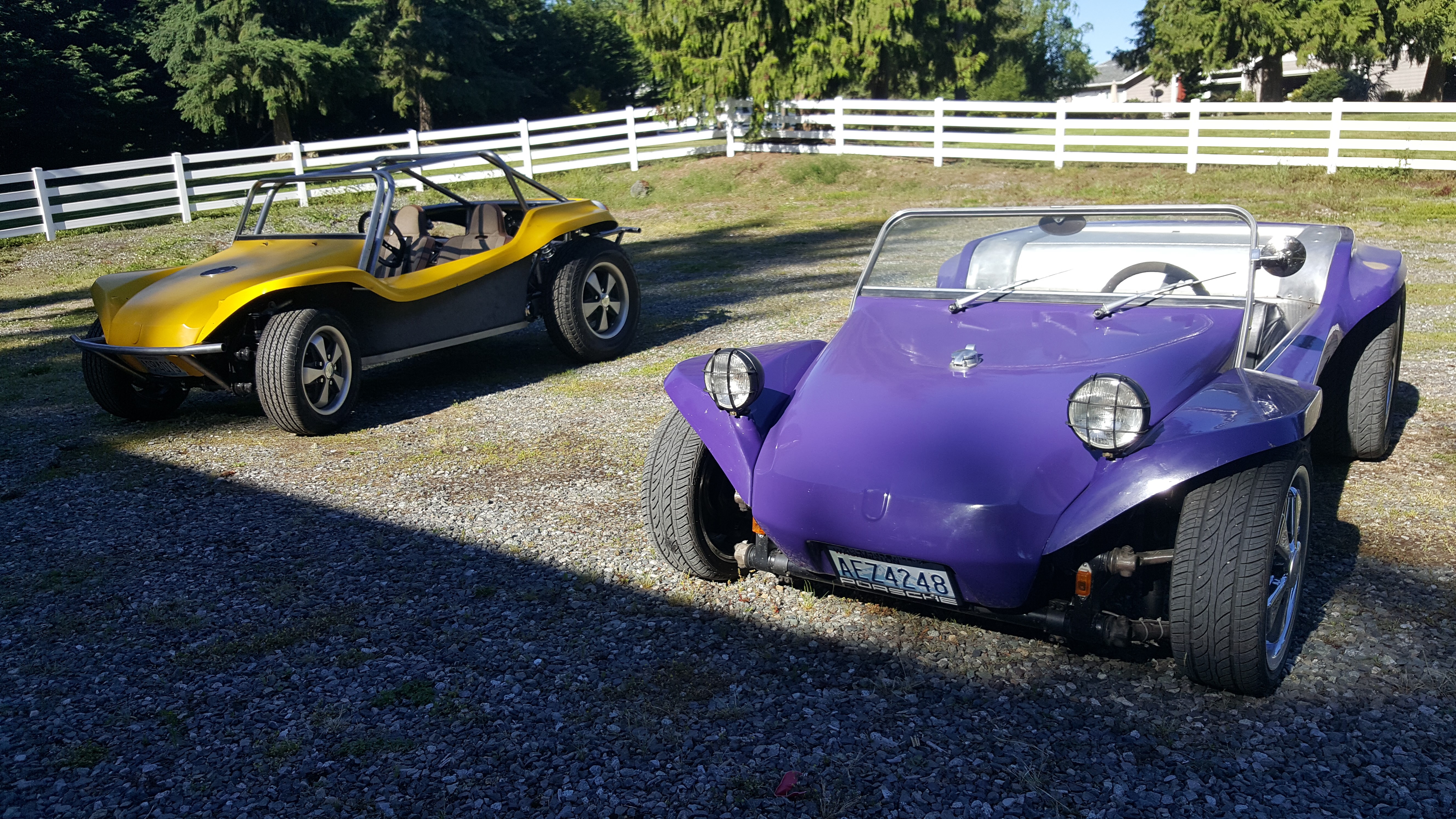
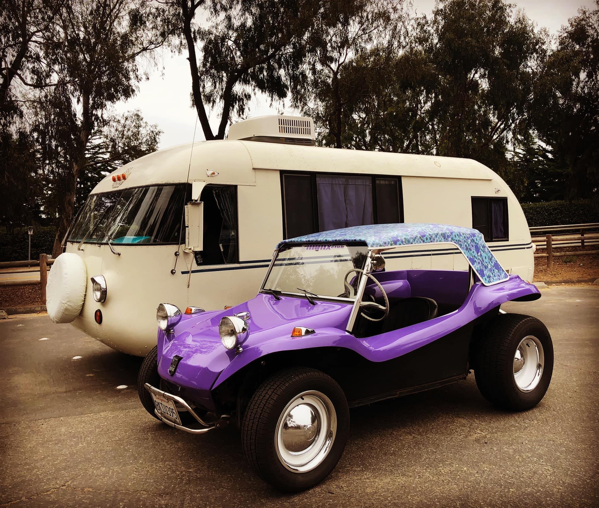
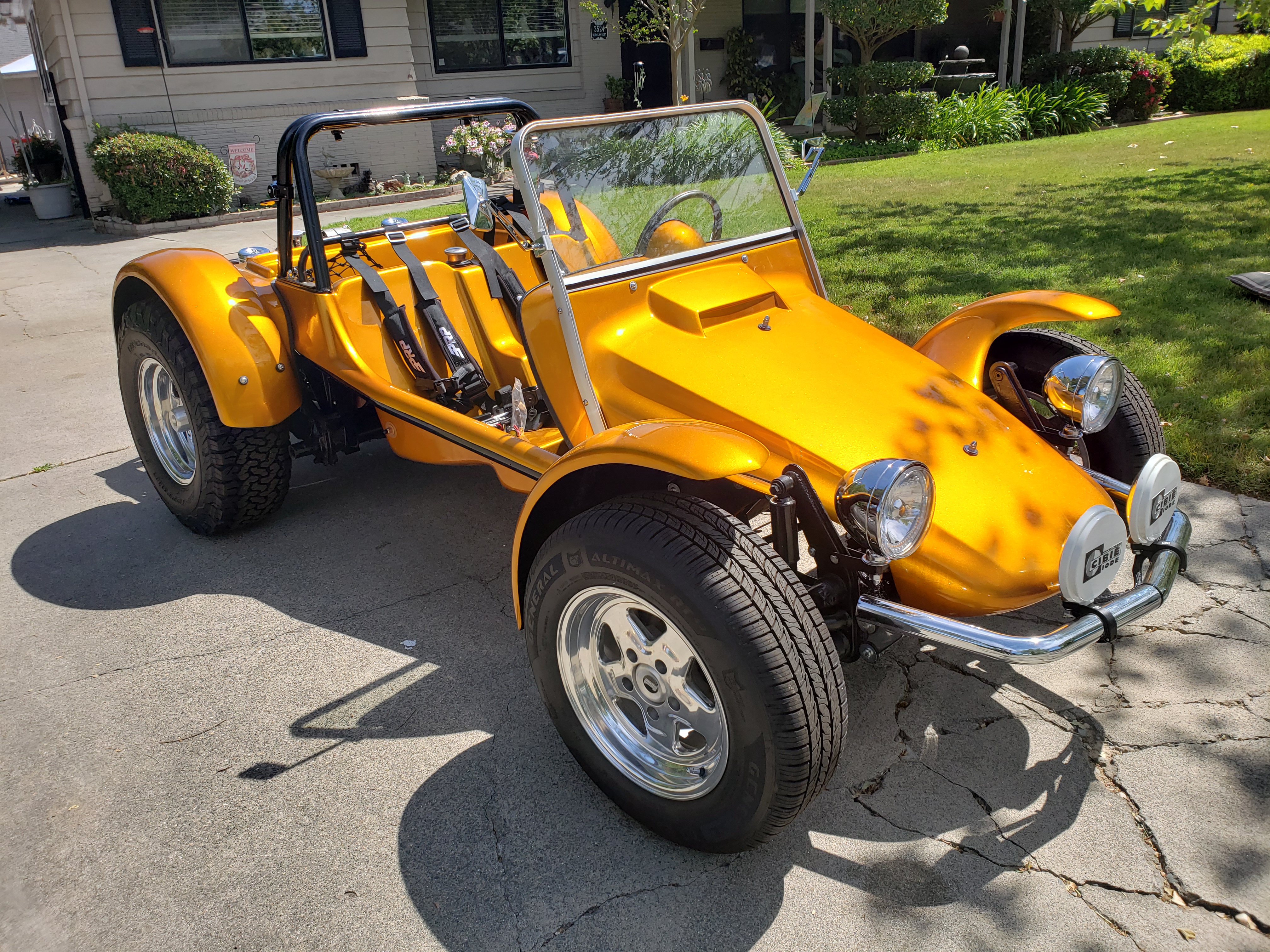
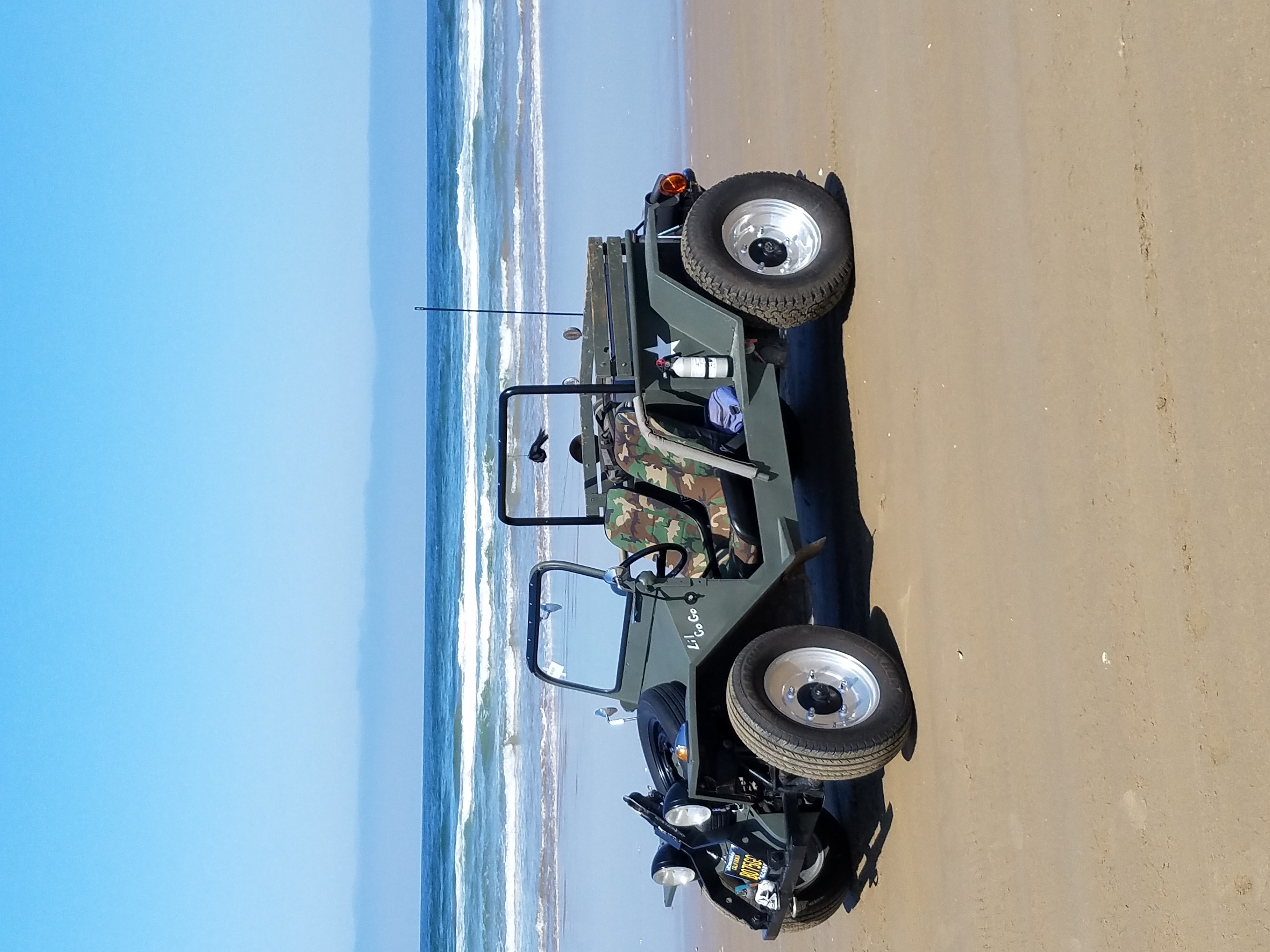
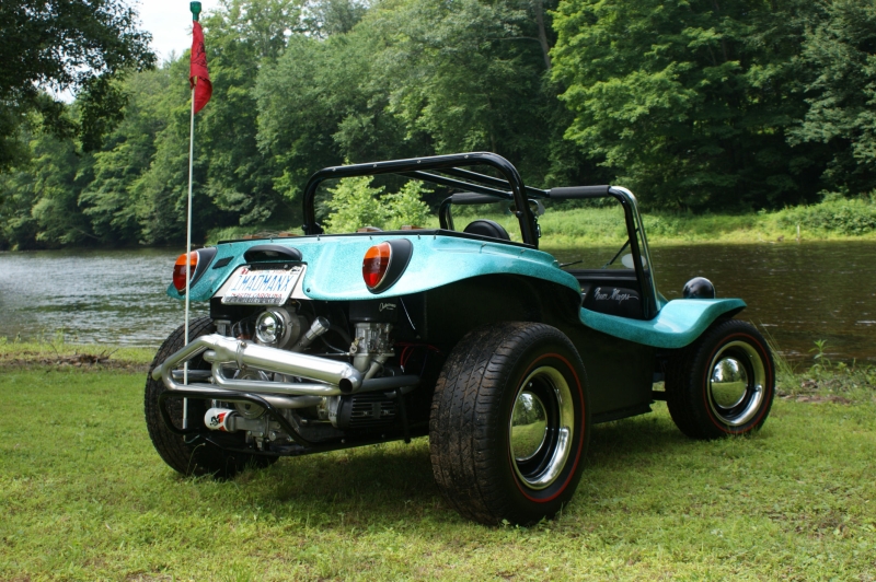
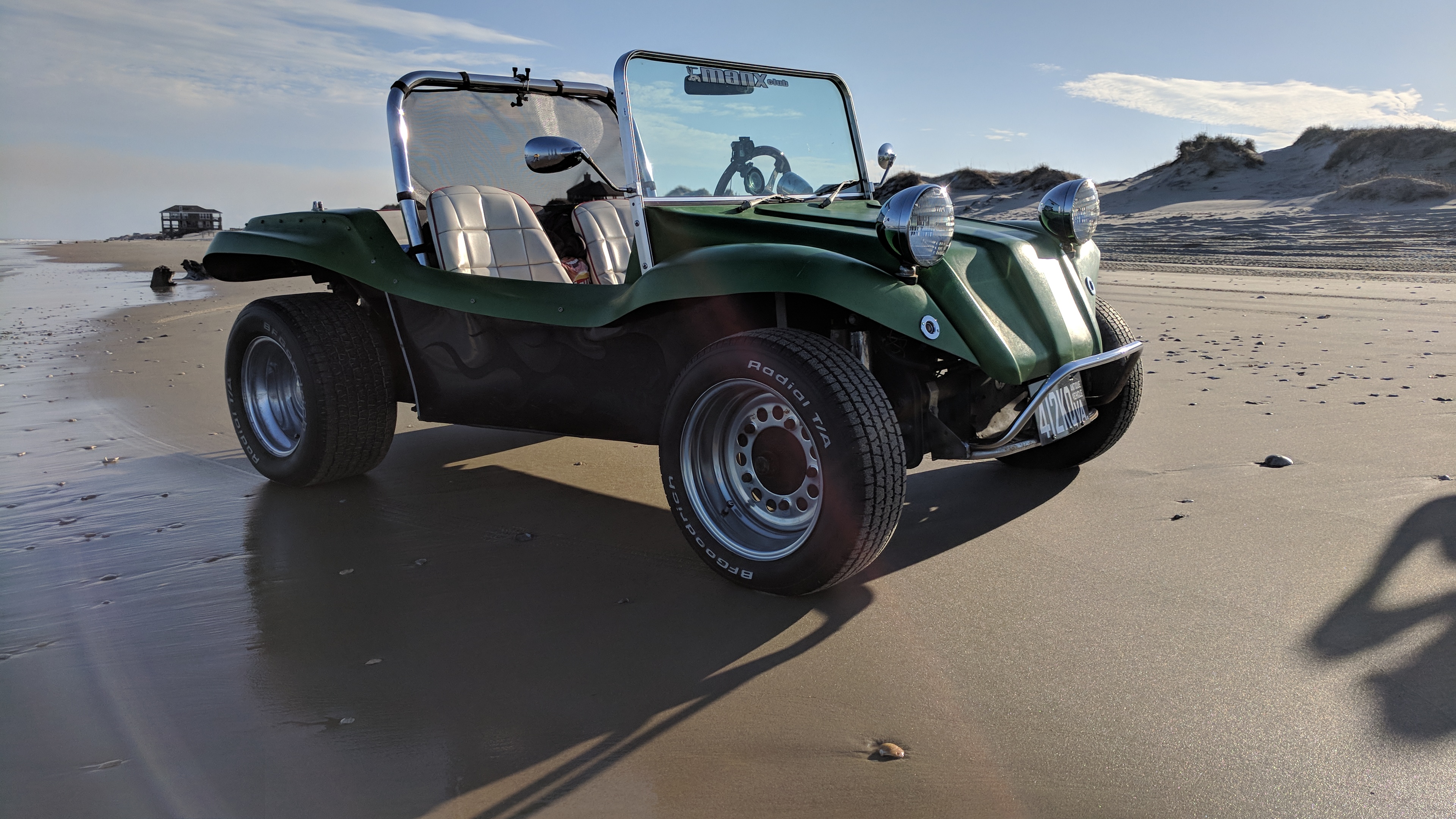
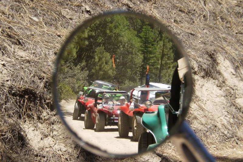
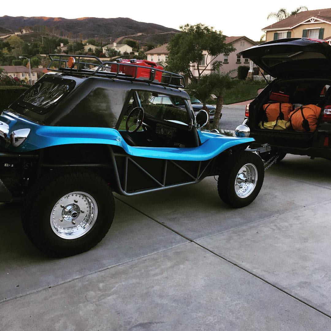
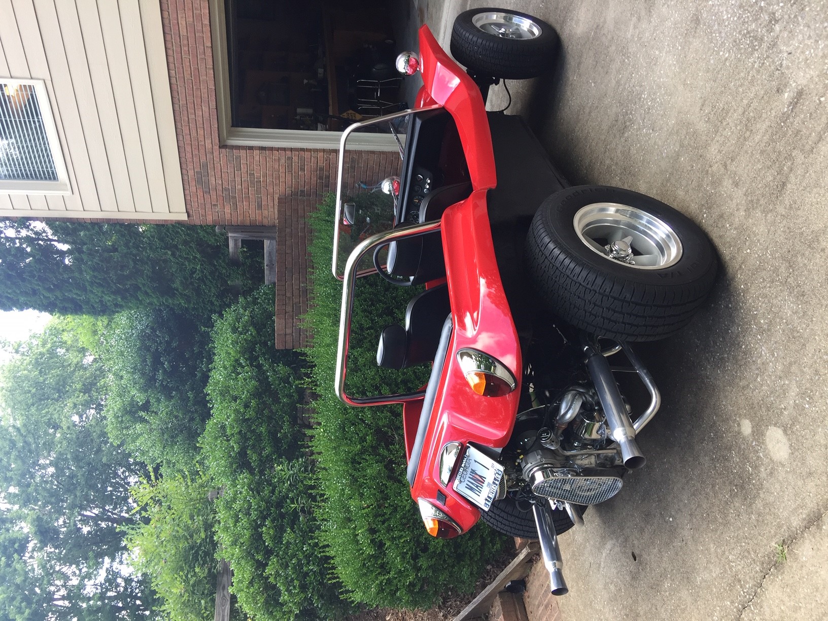
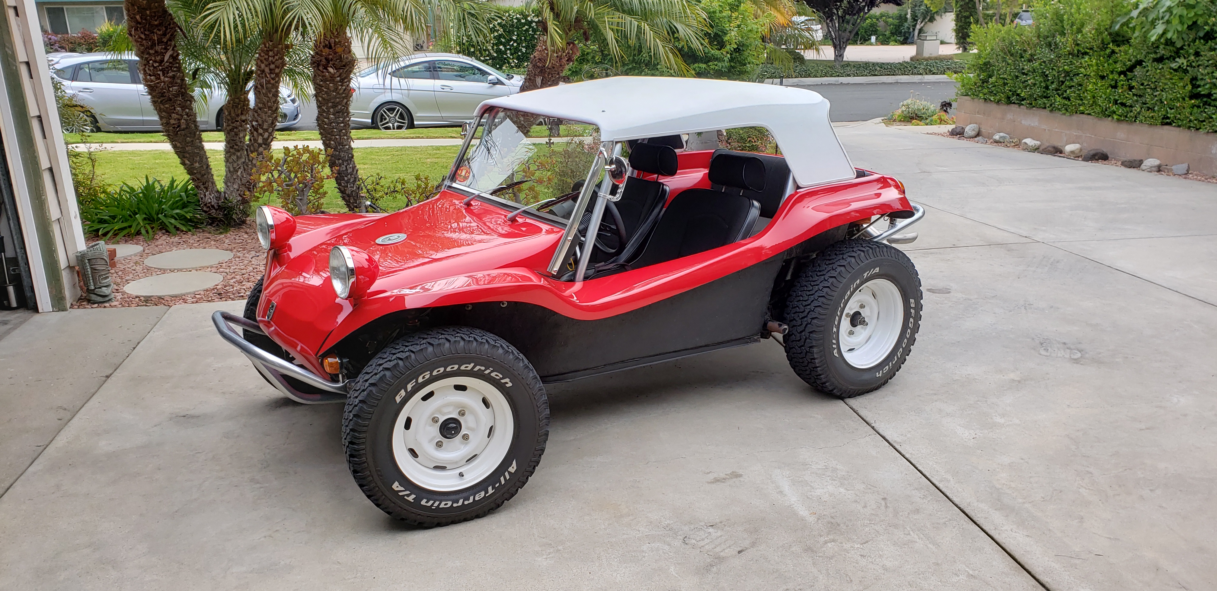
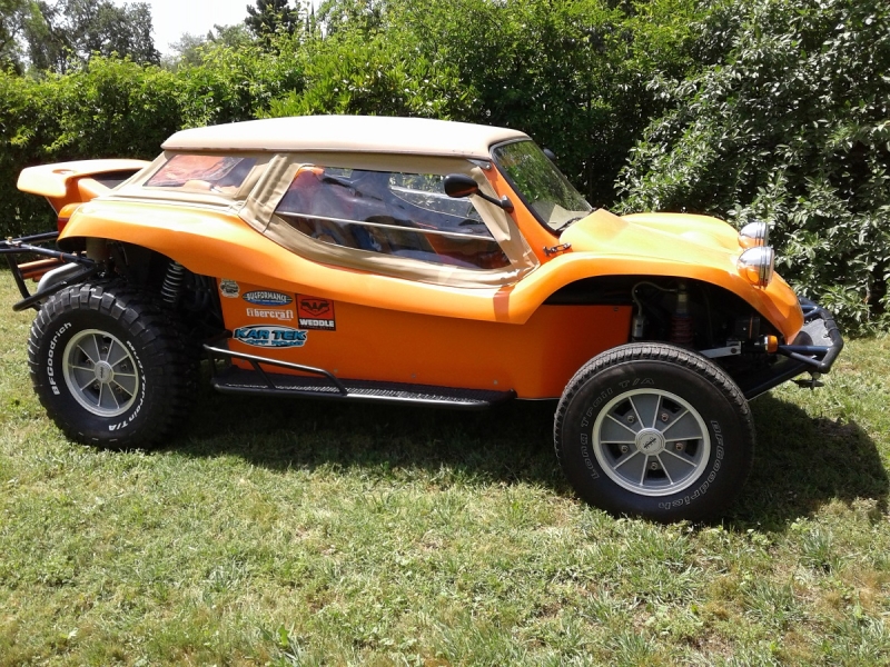
Celebrating the Meyers Manx and all its clones — from the original 1960s beach buggy to today's builds. A community of builders, drivers, and enthusiasts.
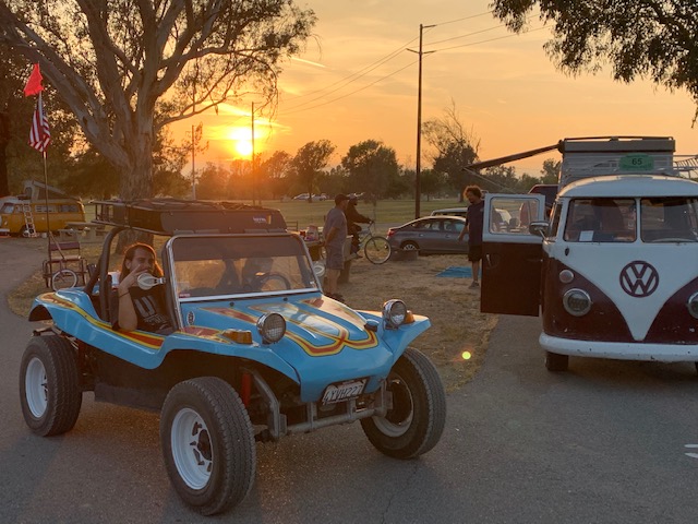
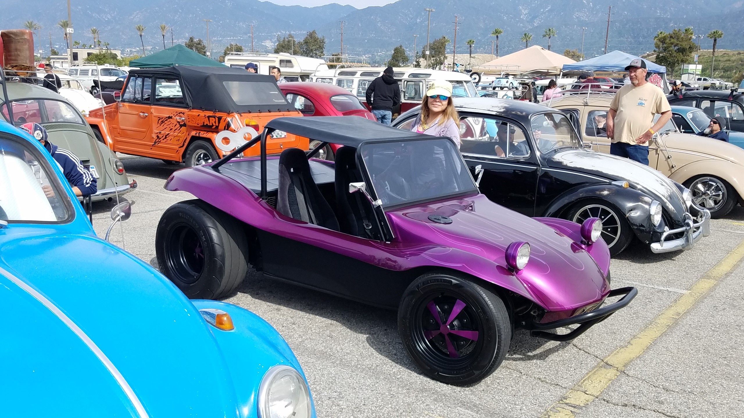
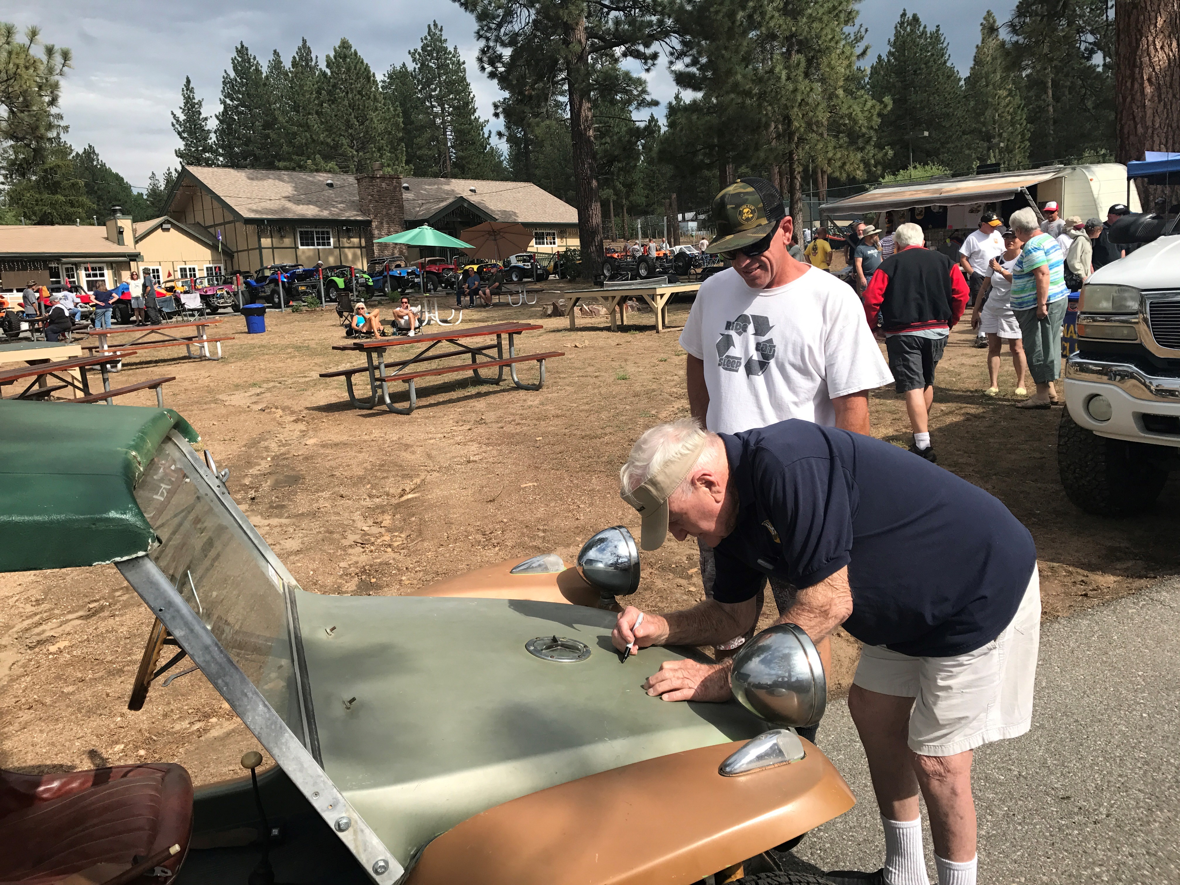
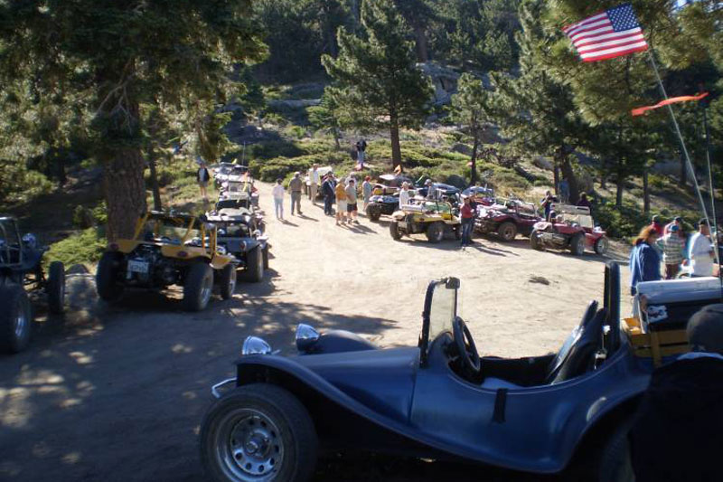
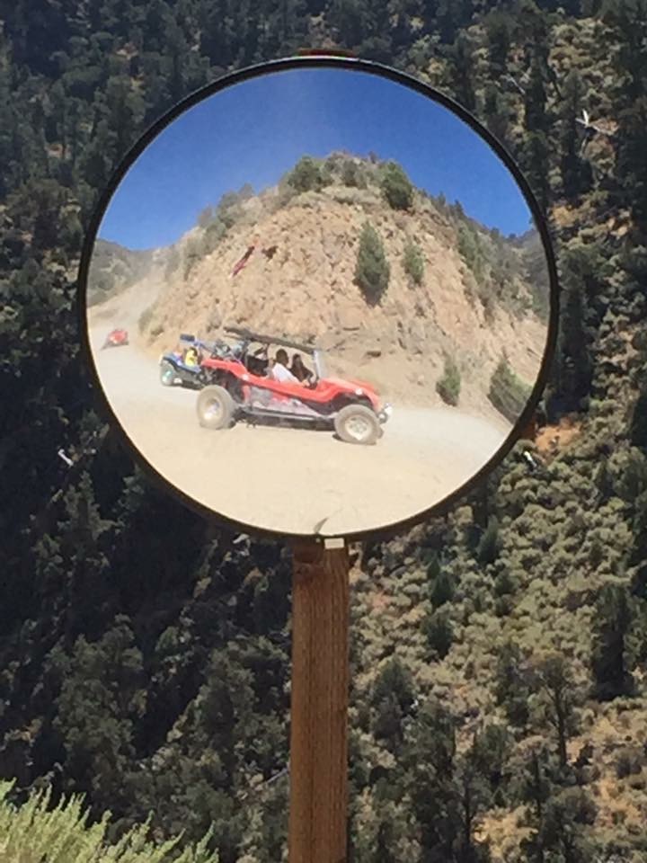
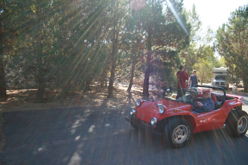
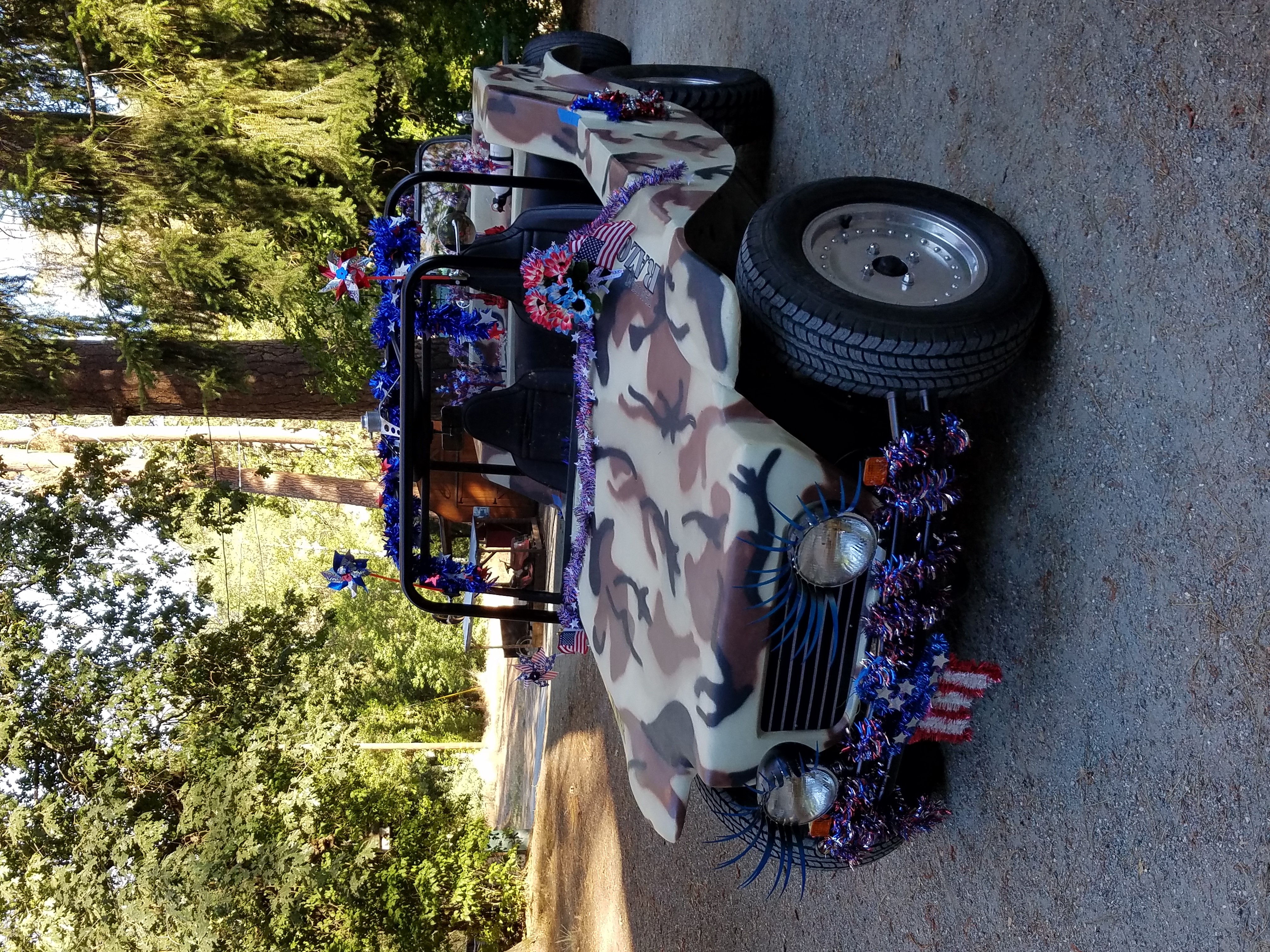
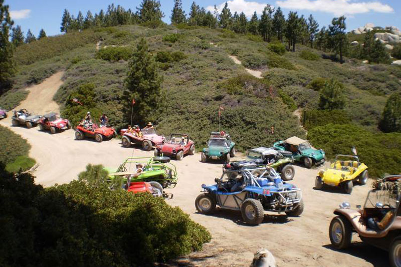
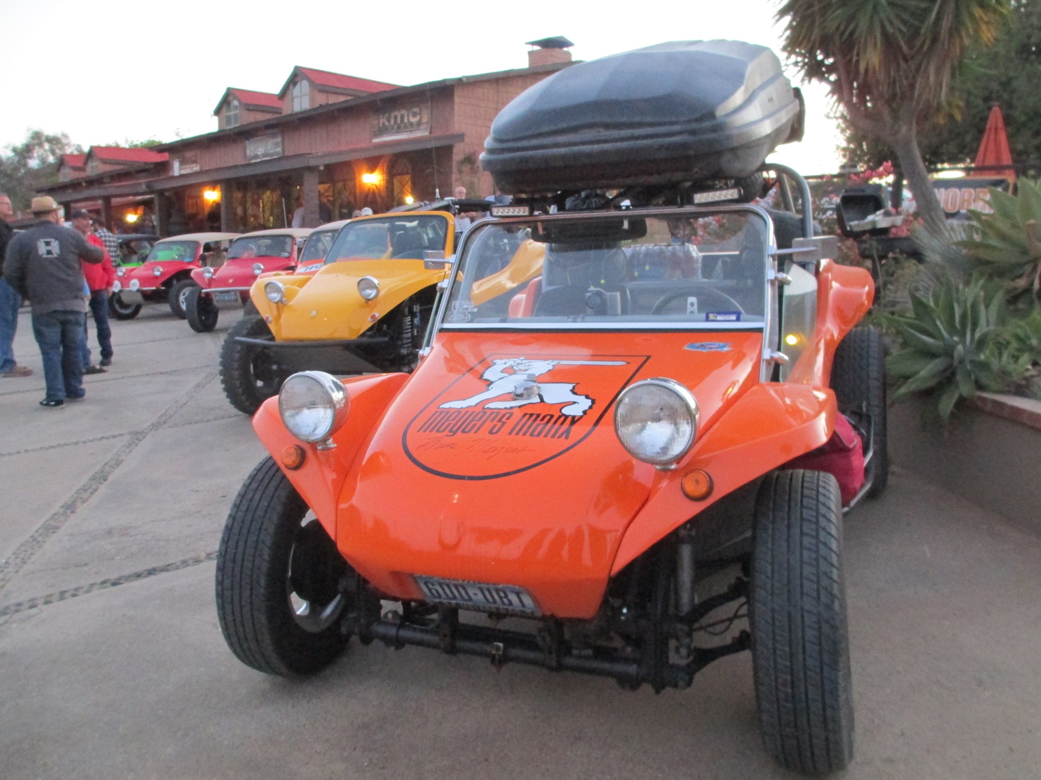
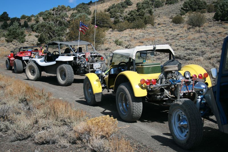
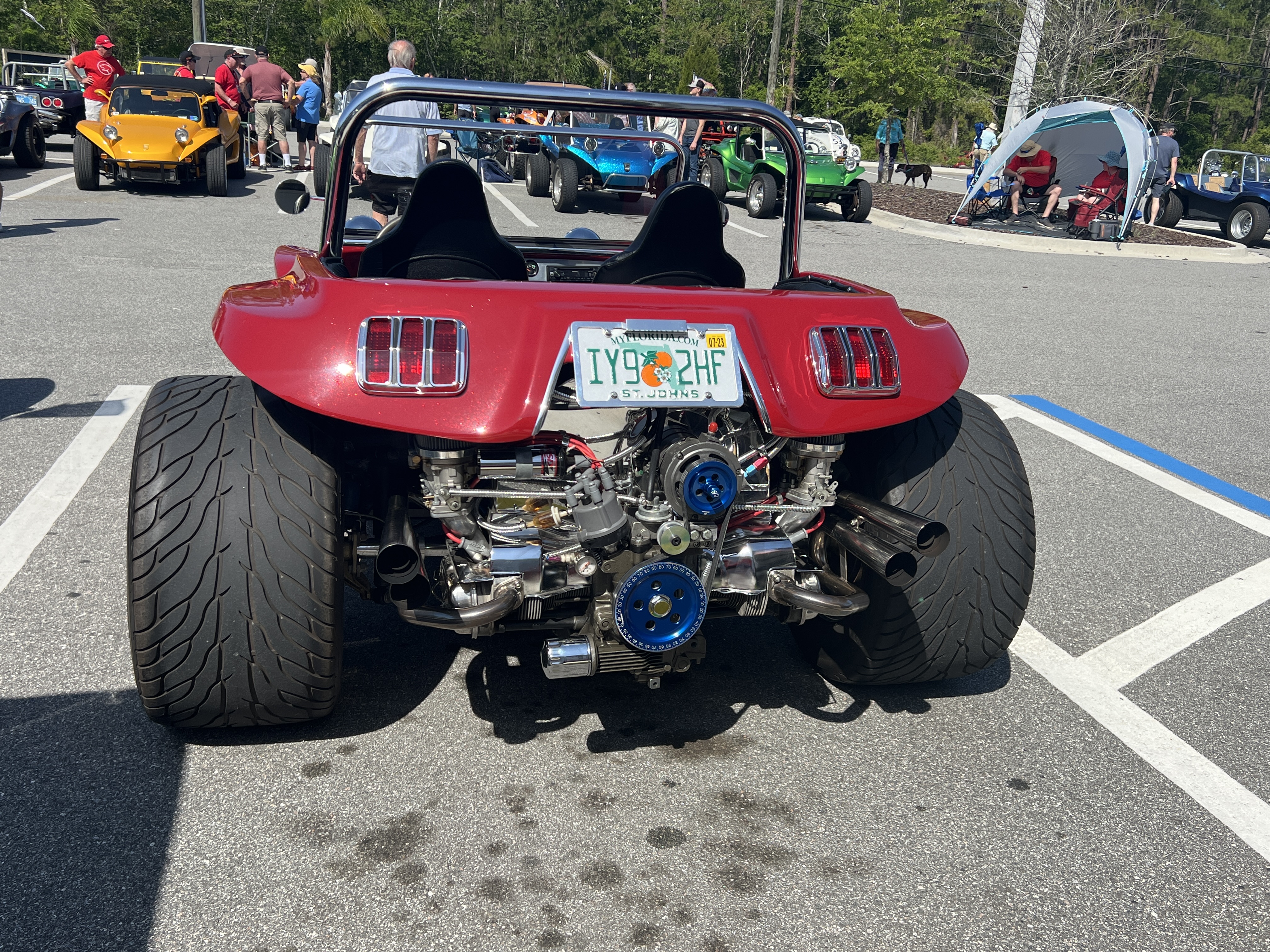
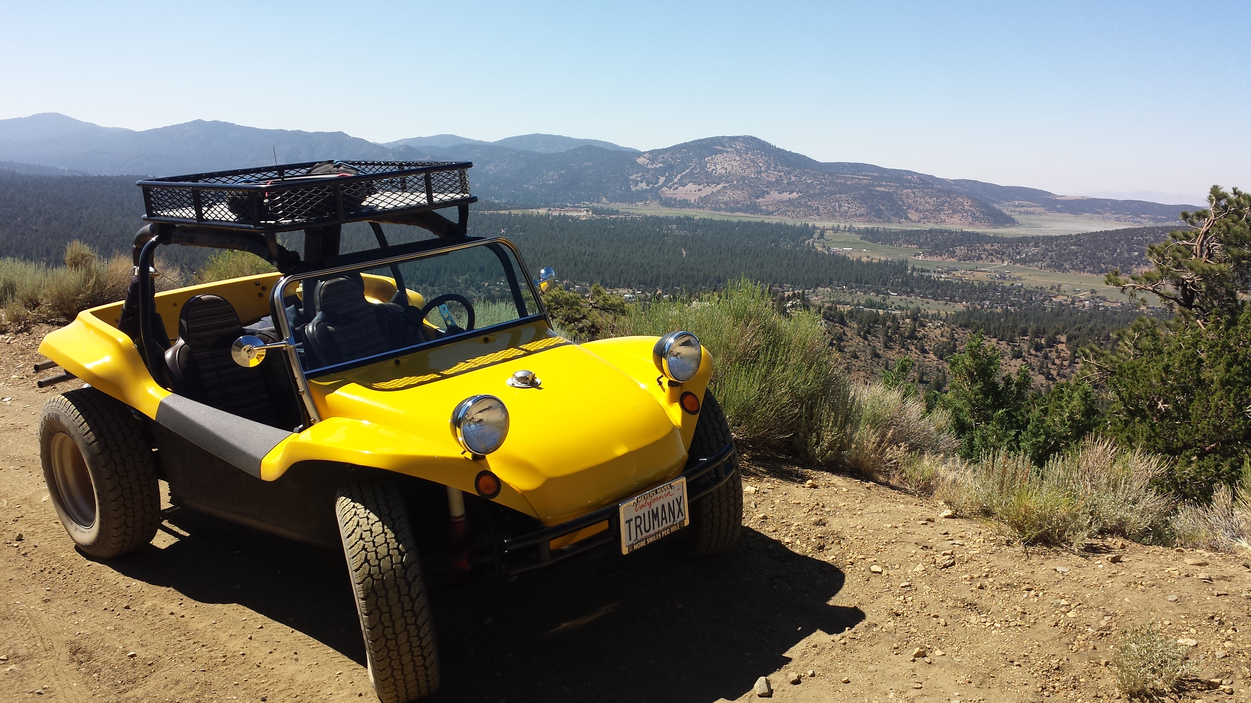
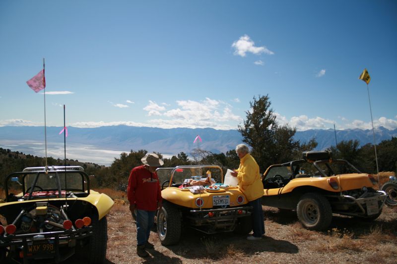
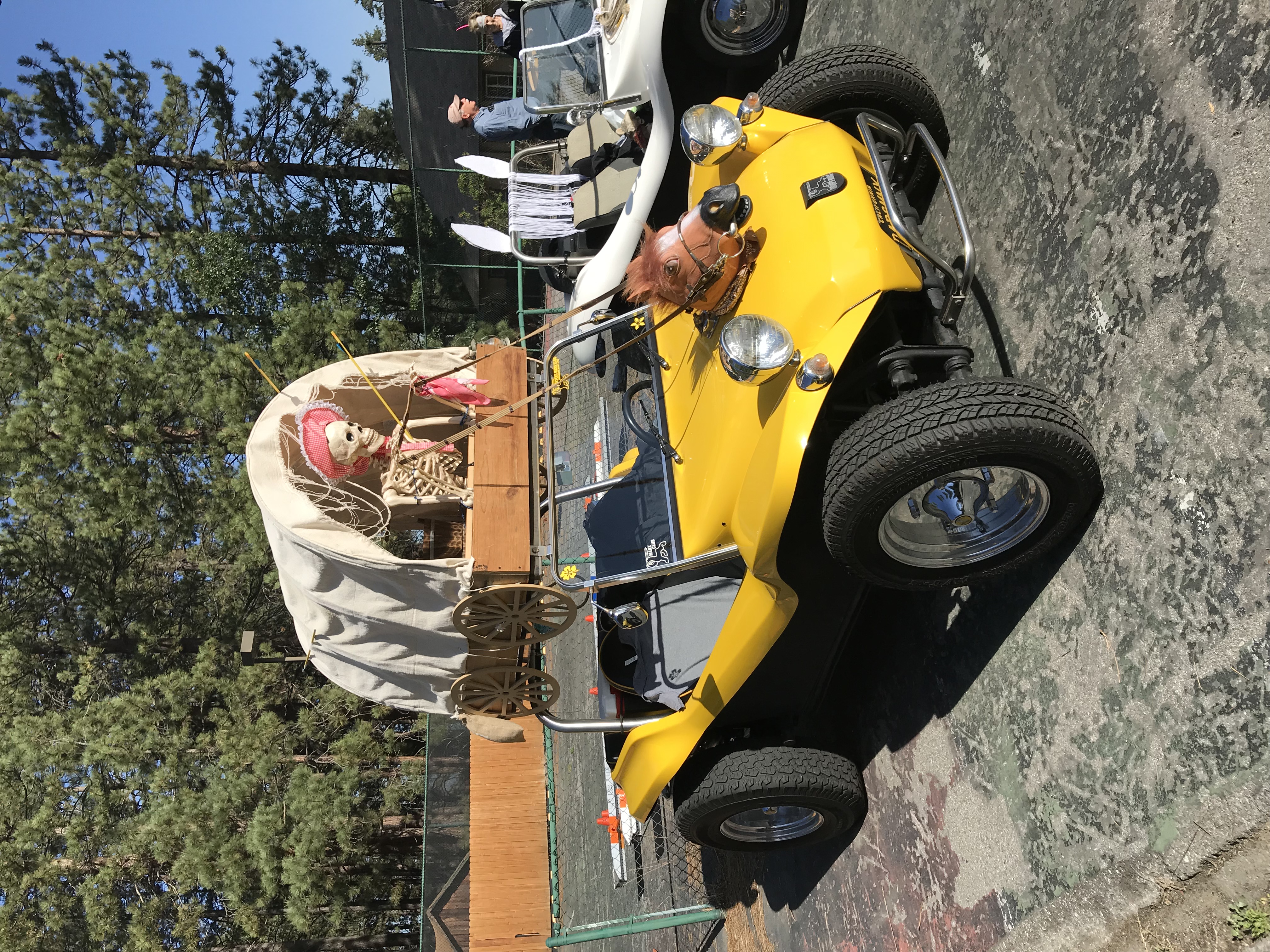
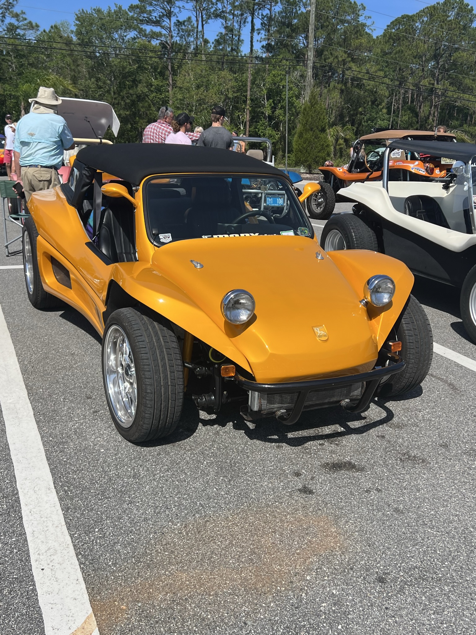
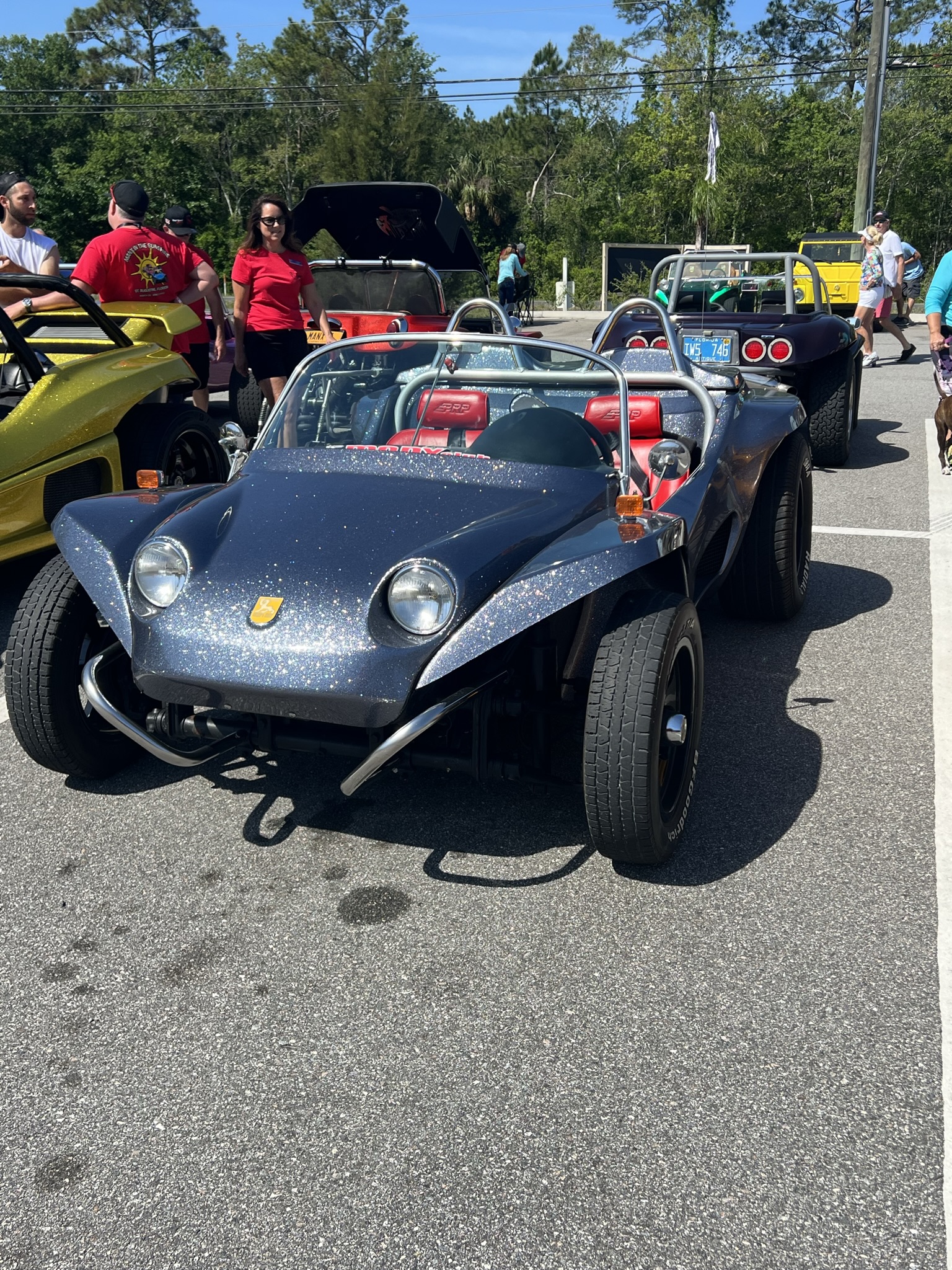
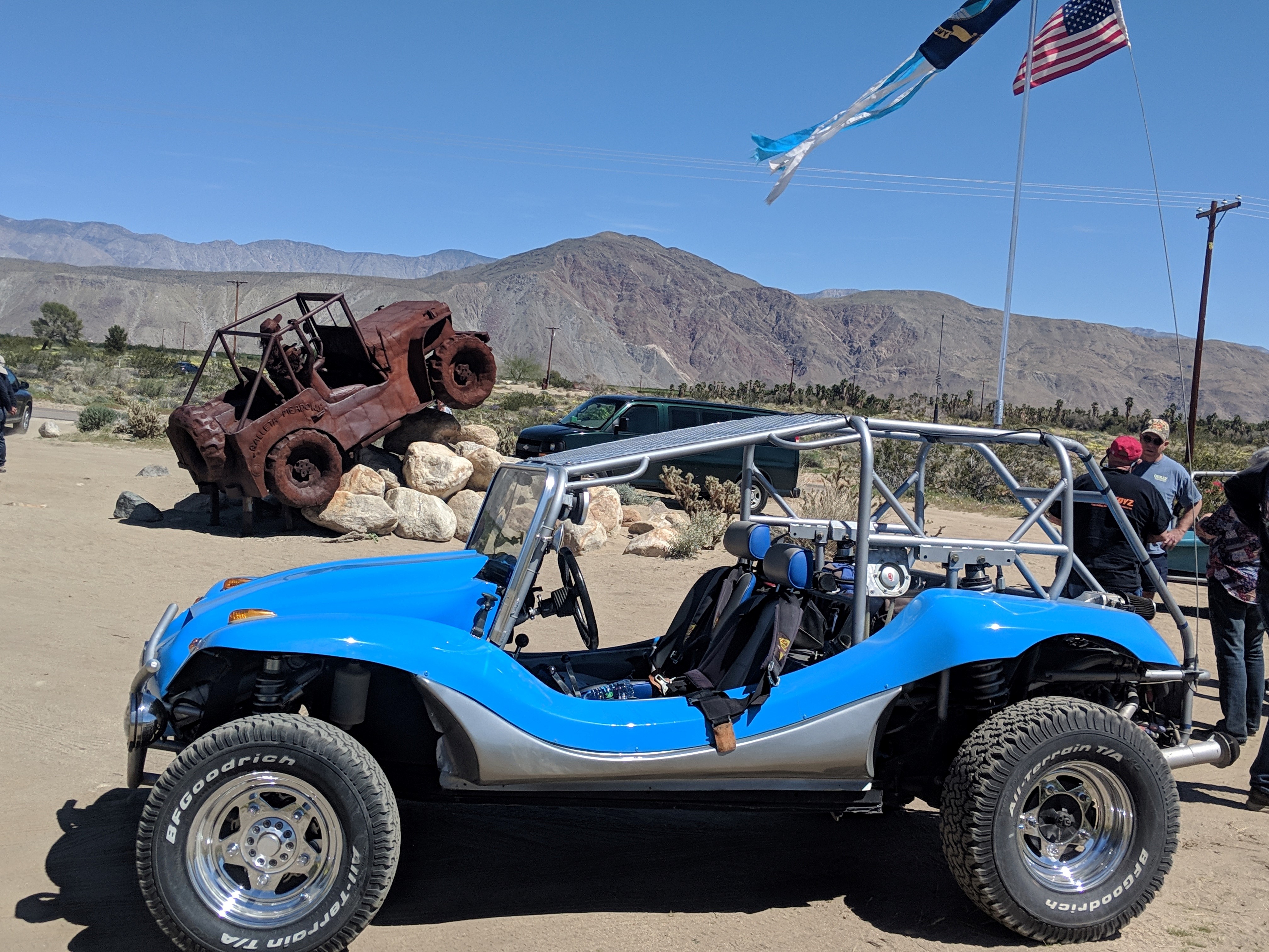
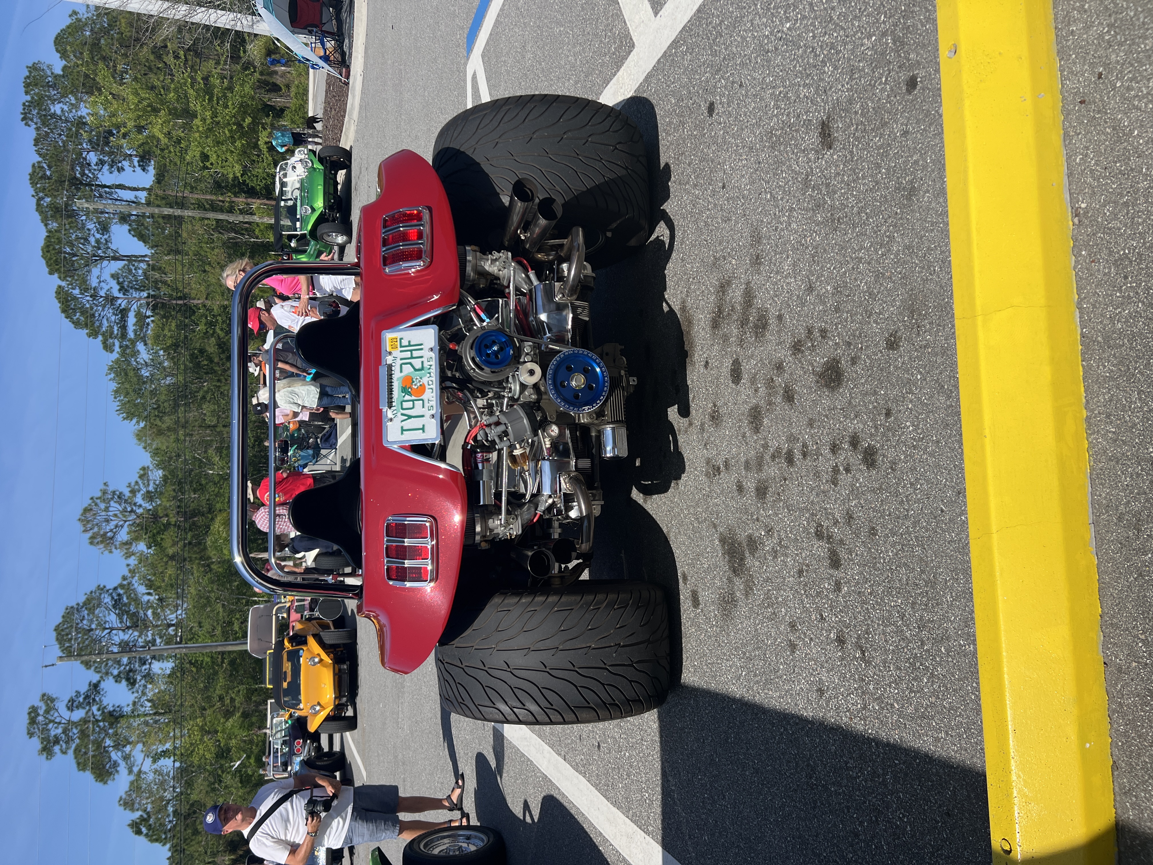
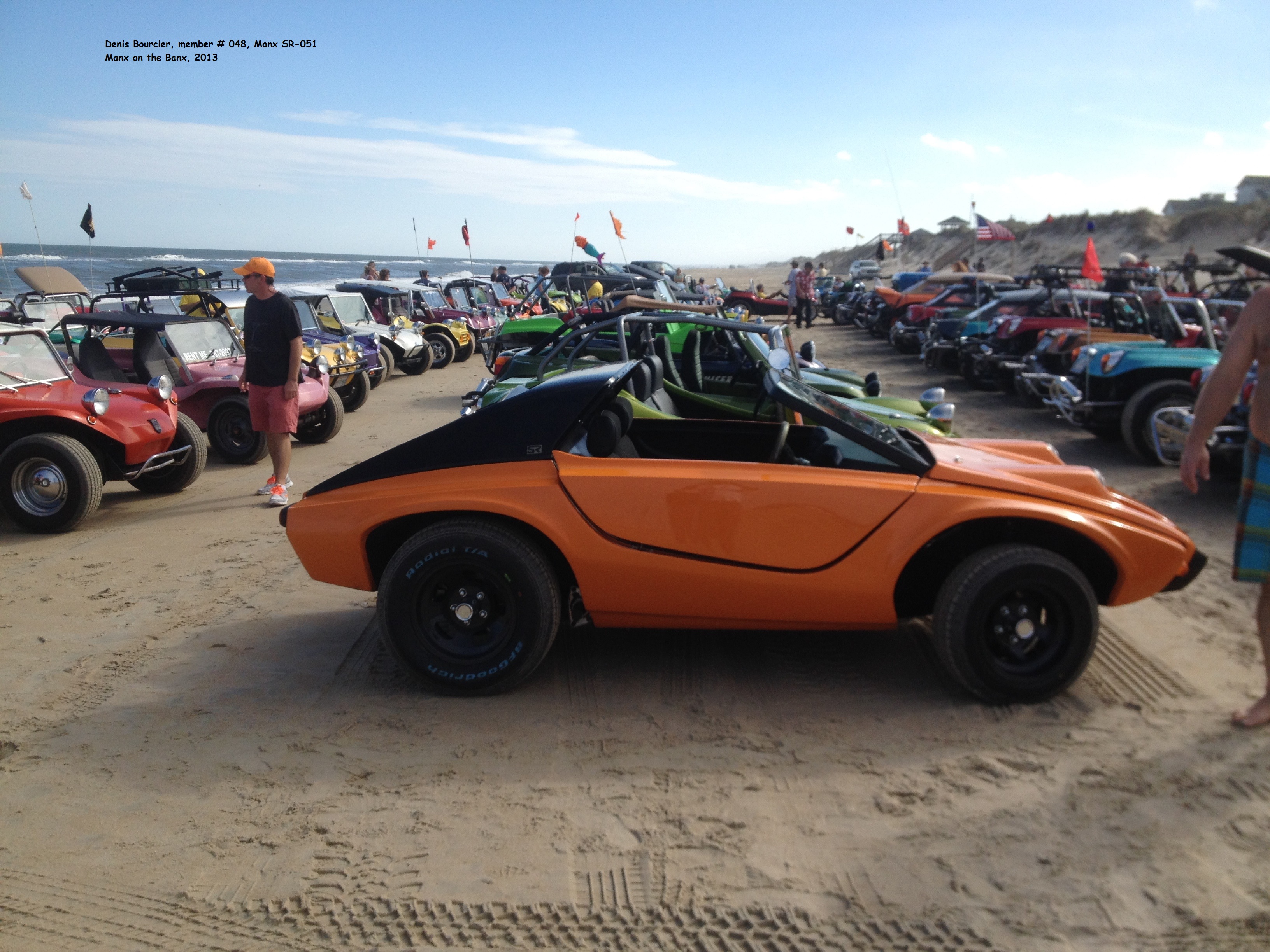
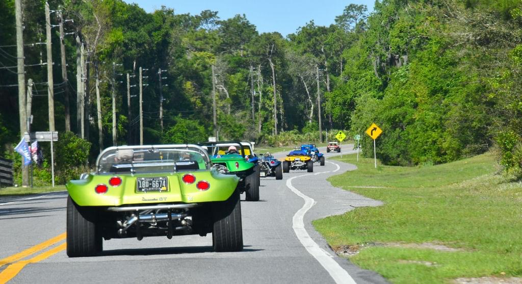
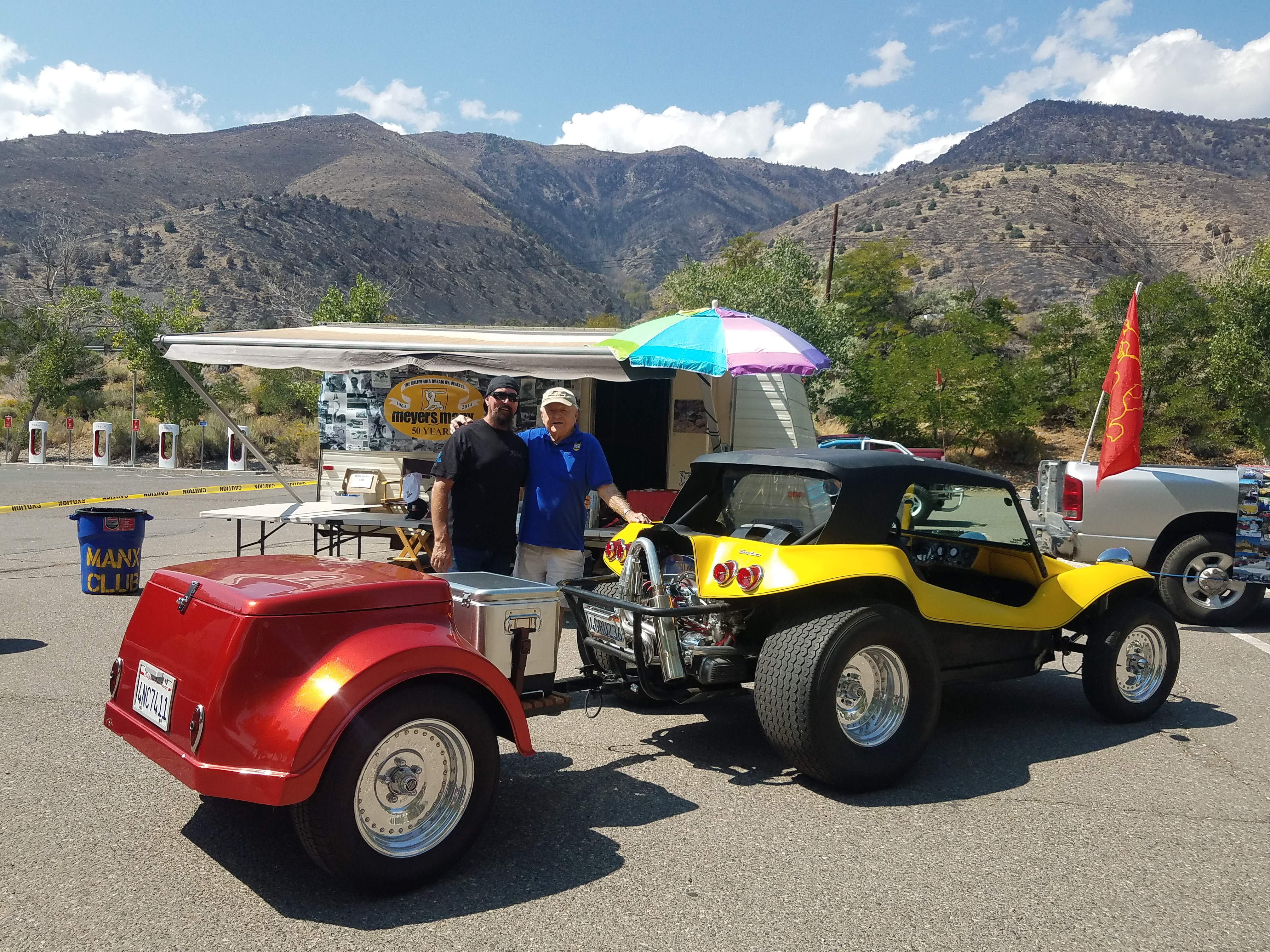
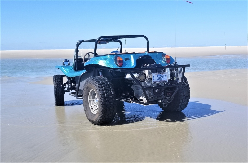
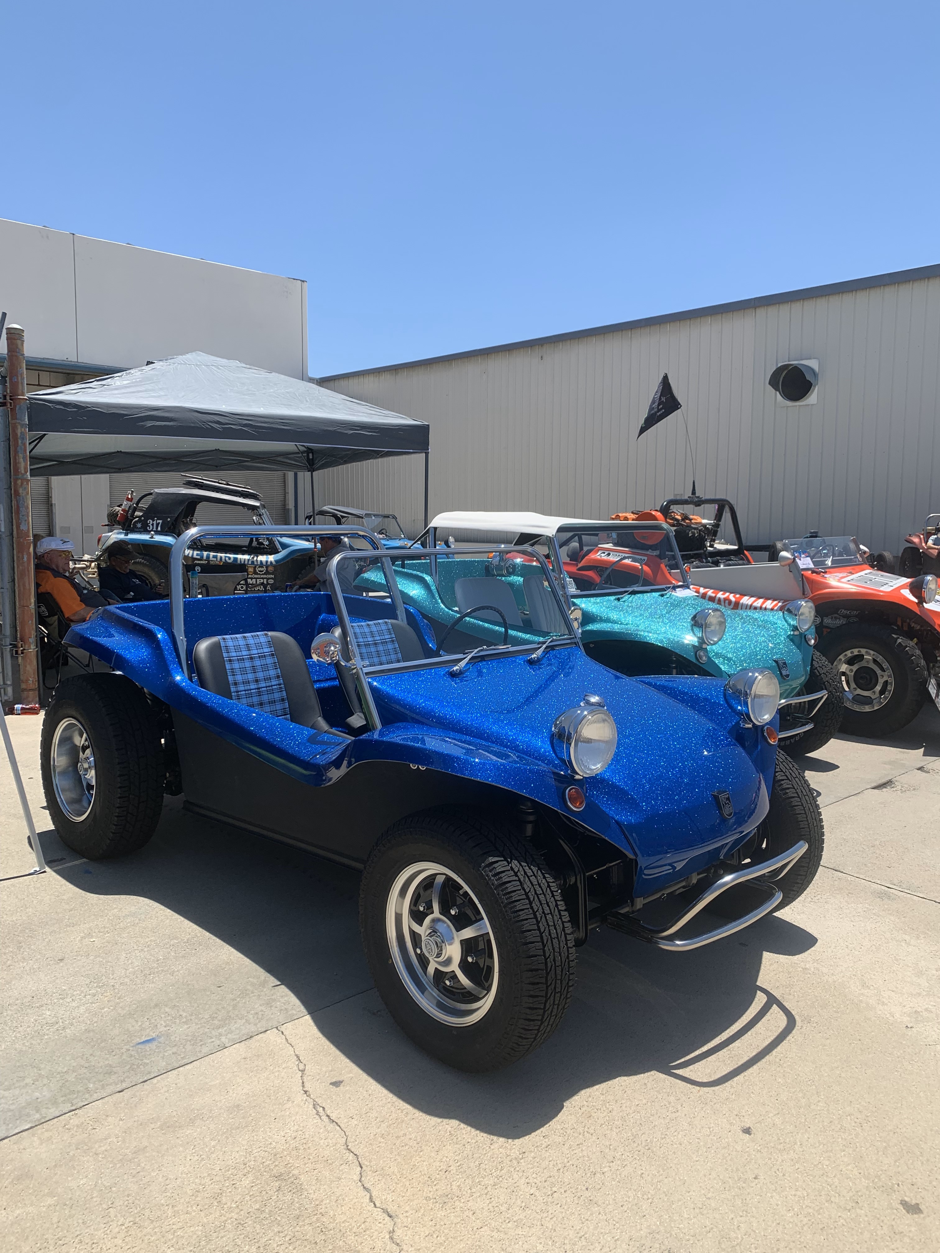
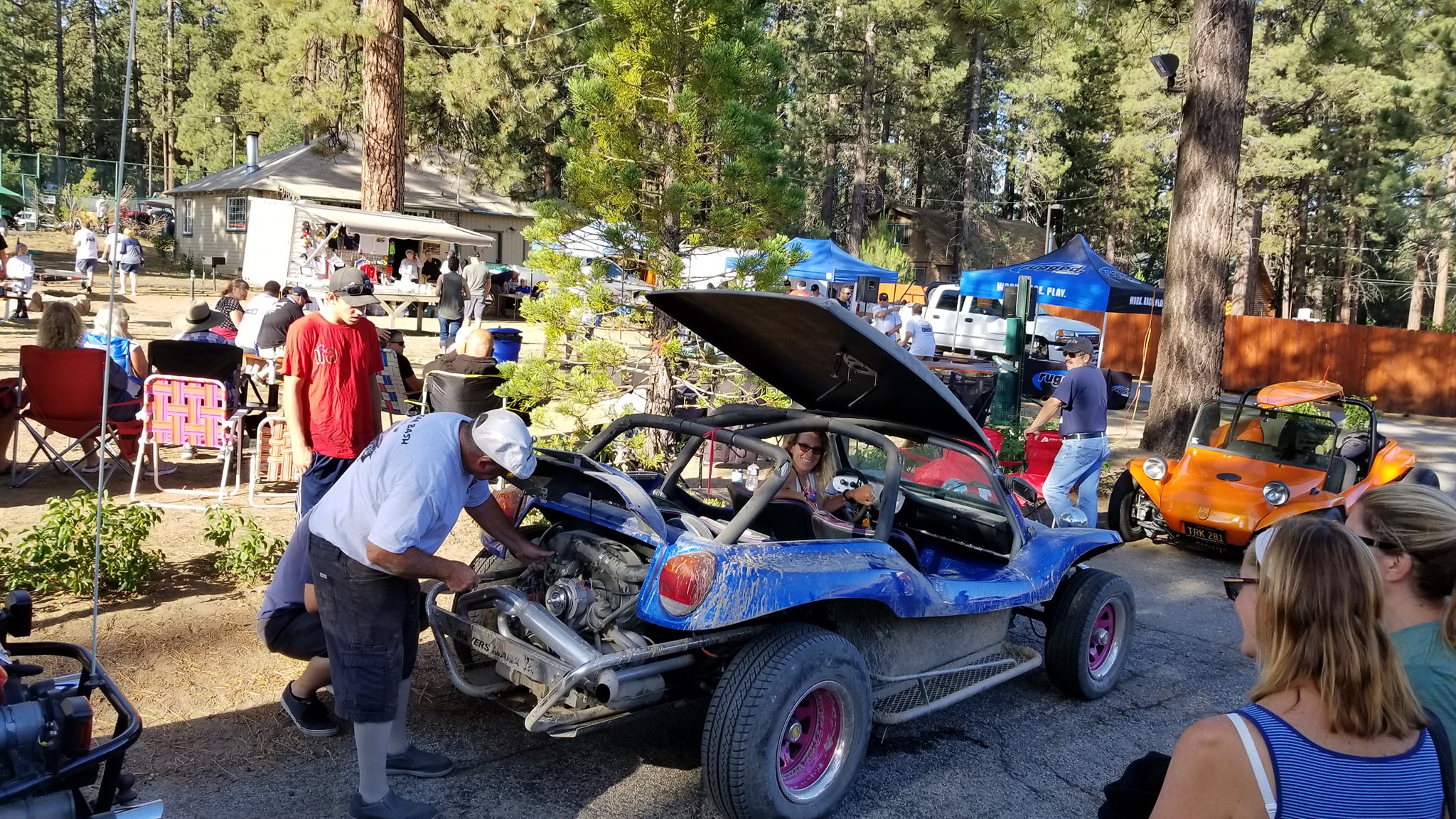
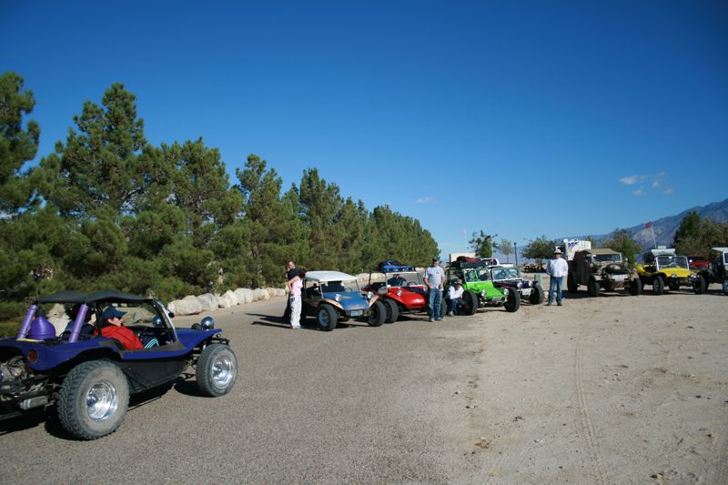
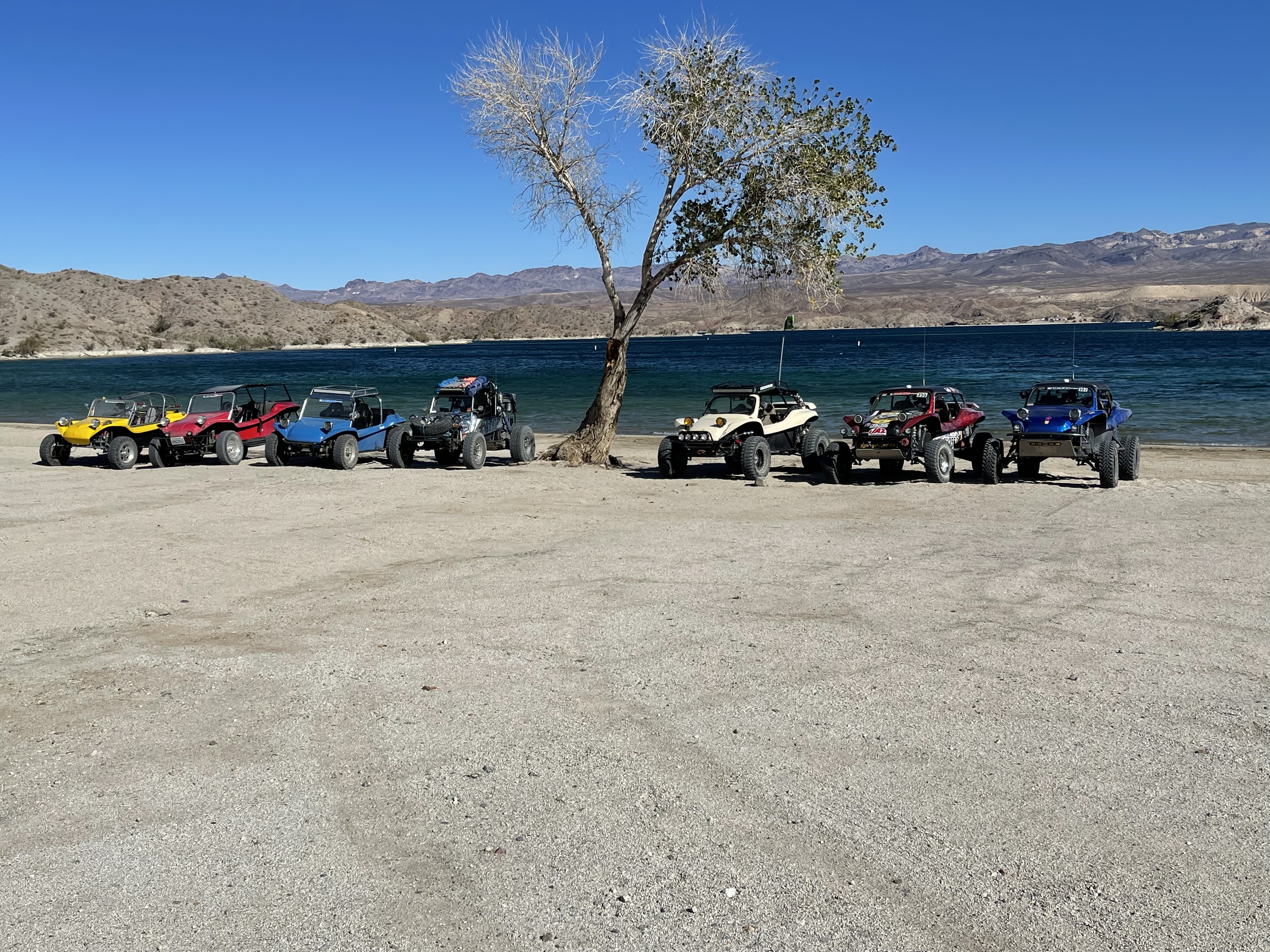
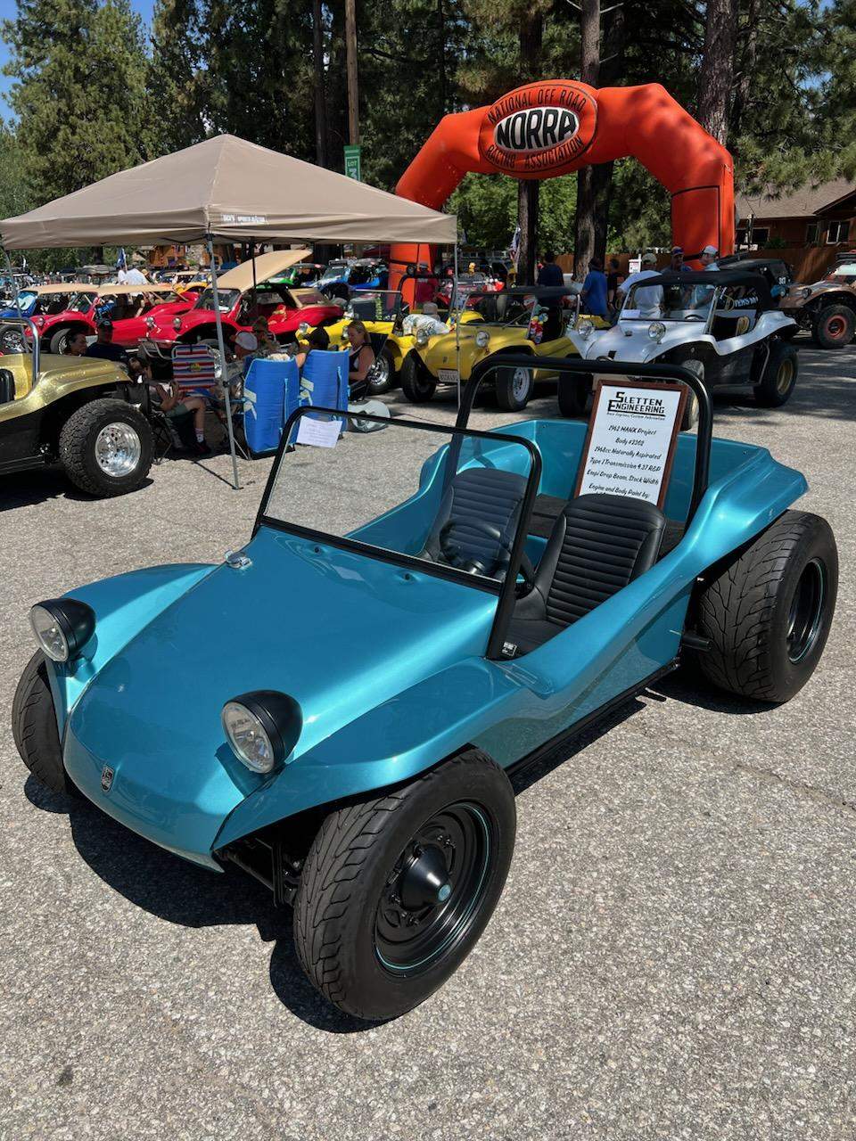
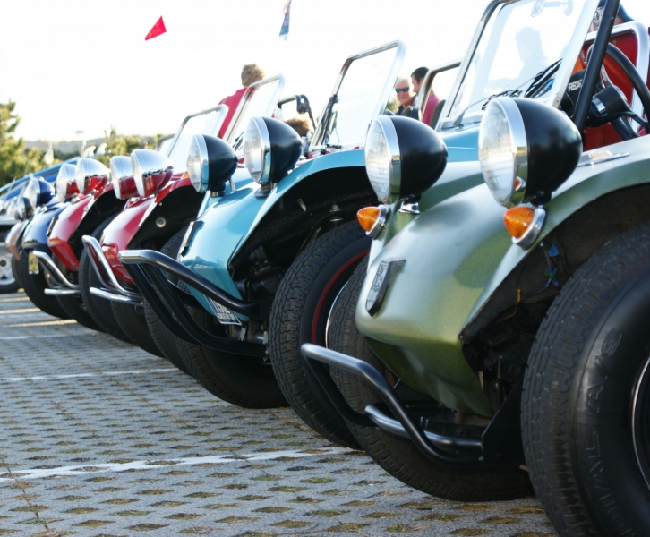
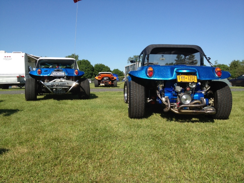
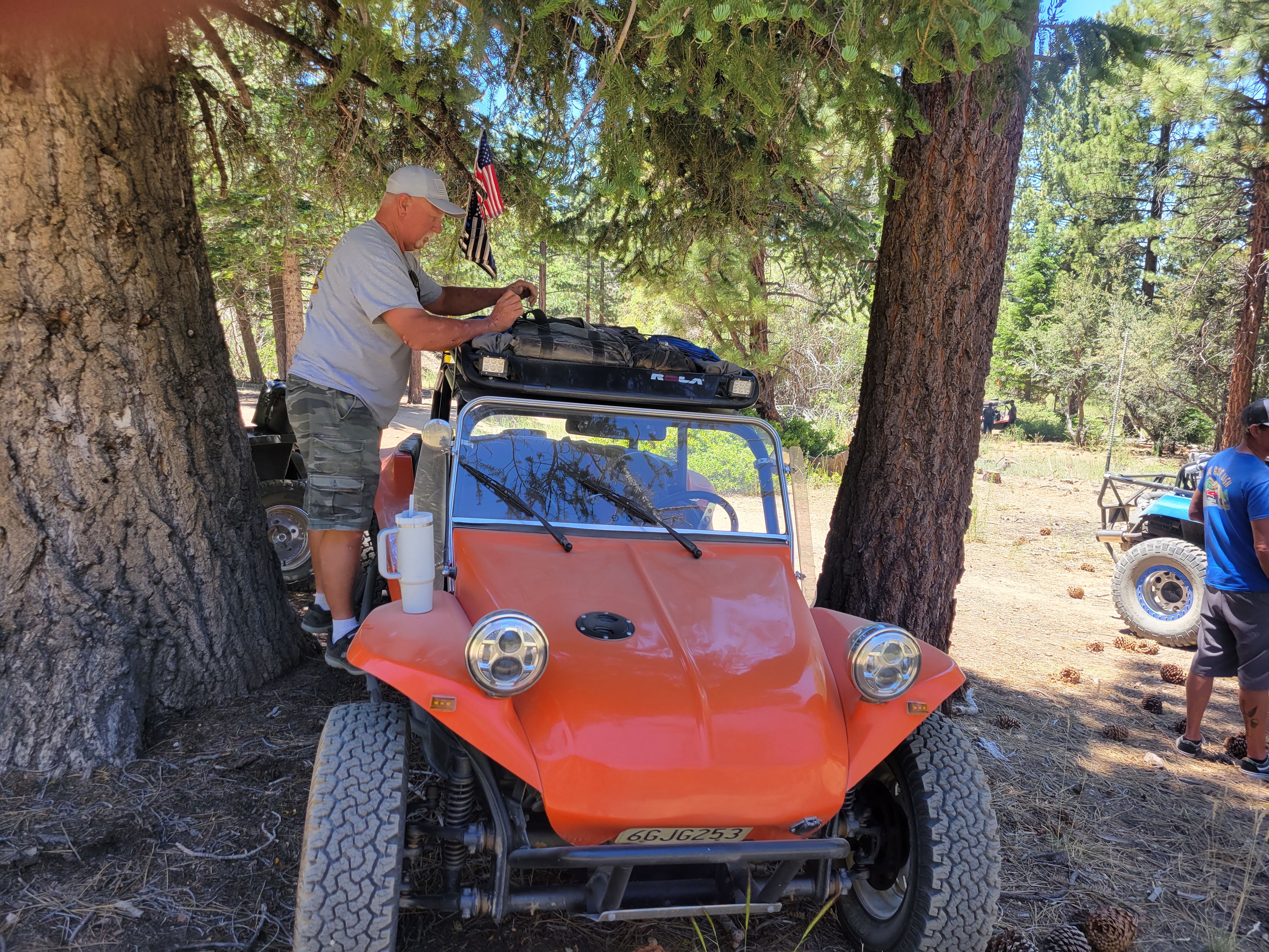
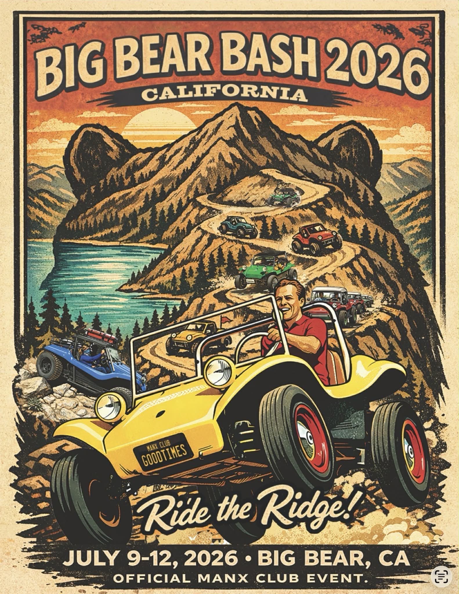
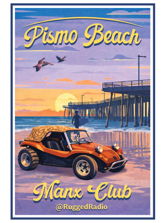
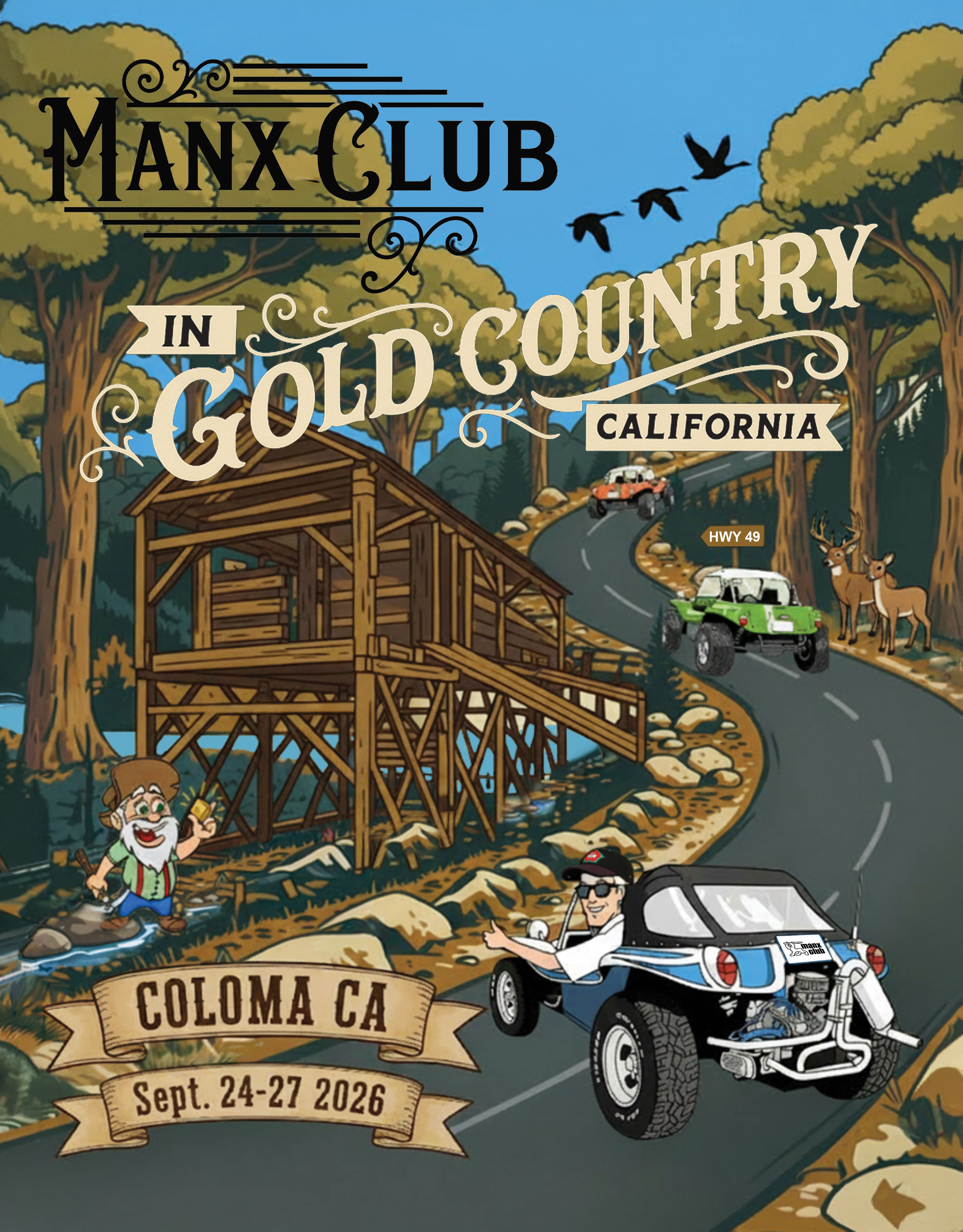
Get out there — official runs, shows, and gatherings across the country.
Everything you need to know about the Meyers Manx and the Manx Club.
Archive of every issue from 2008 to today — Spring, Summer, Fall & Winter editions.
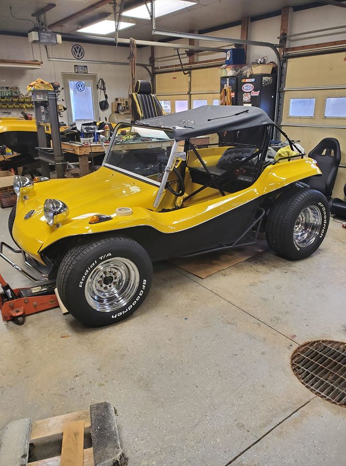
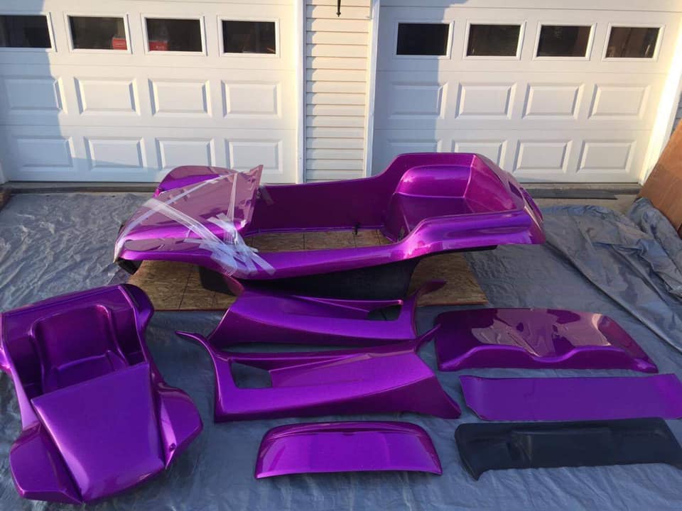
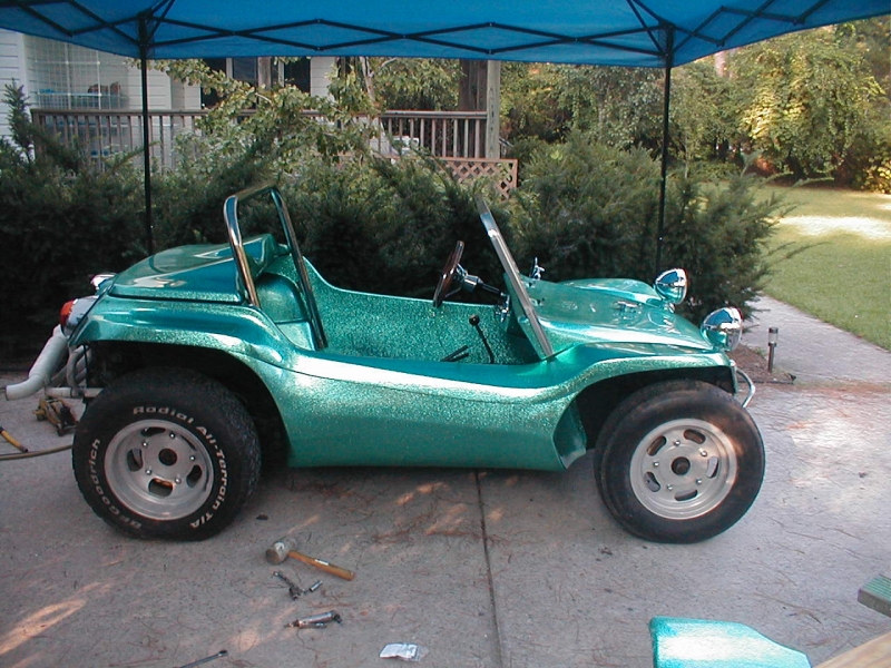
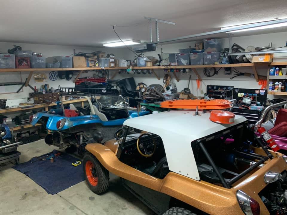
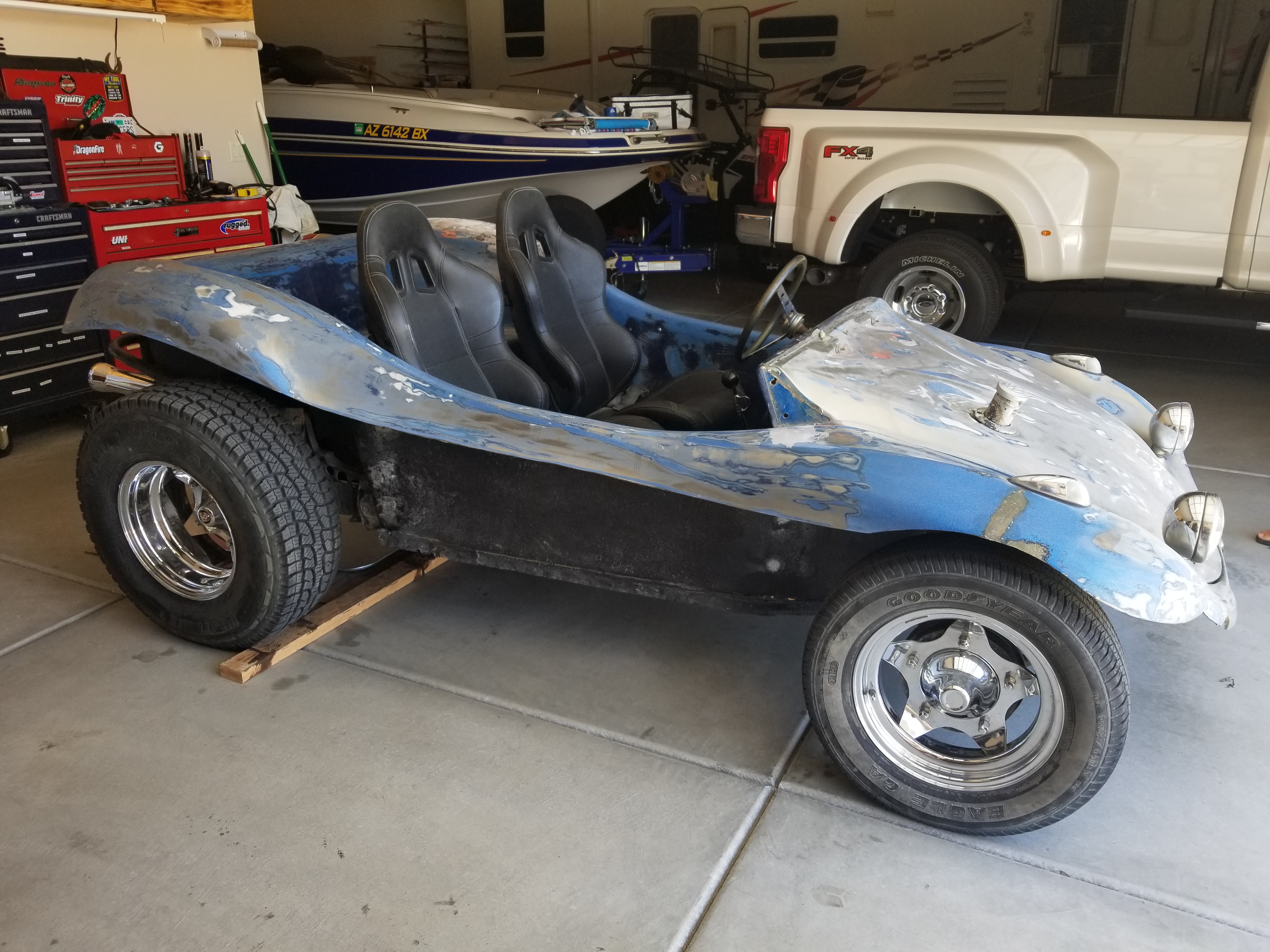
Browse Archive →Build guides, maintenance tips, restoration notes and technical resources for Manx owners.
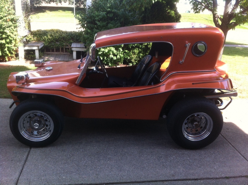
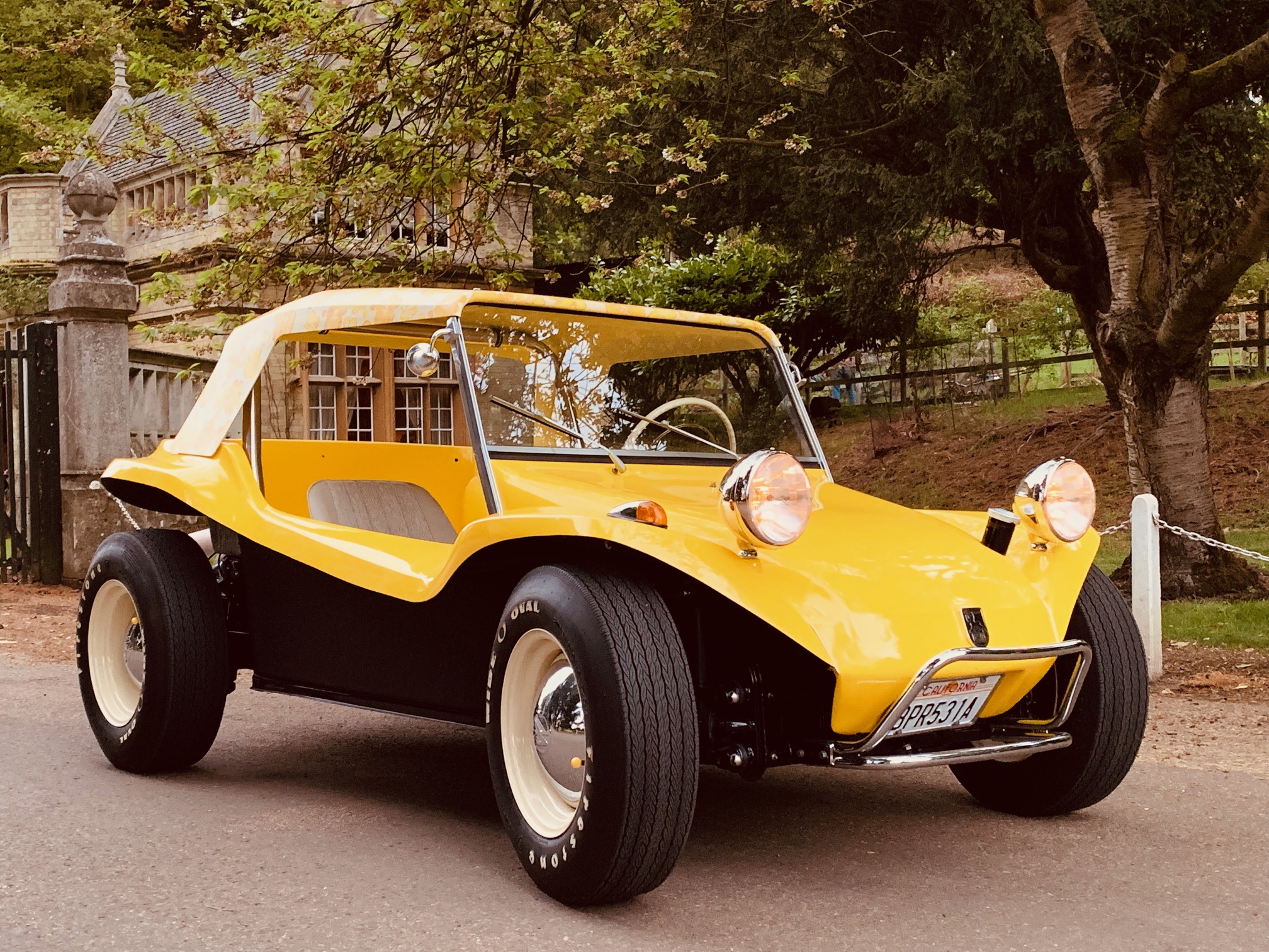
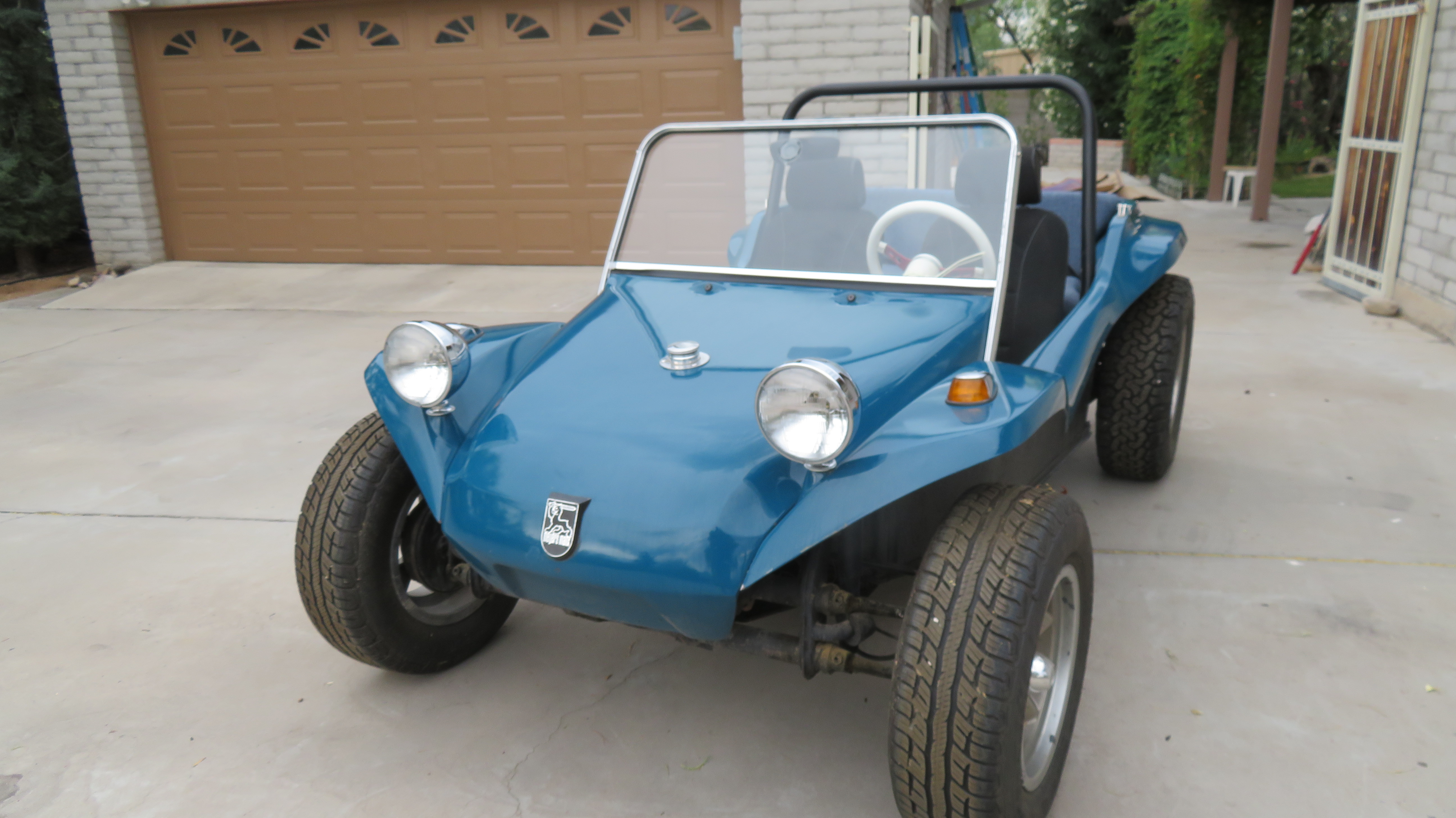
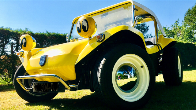
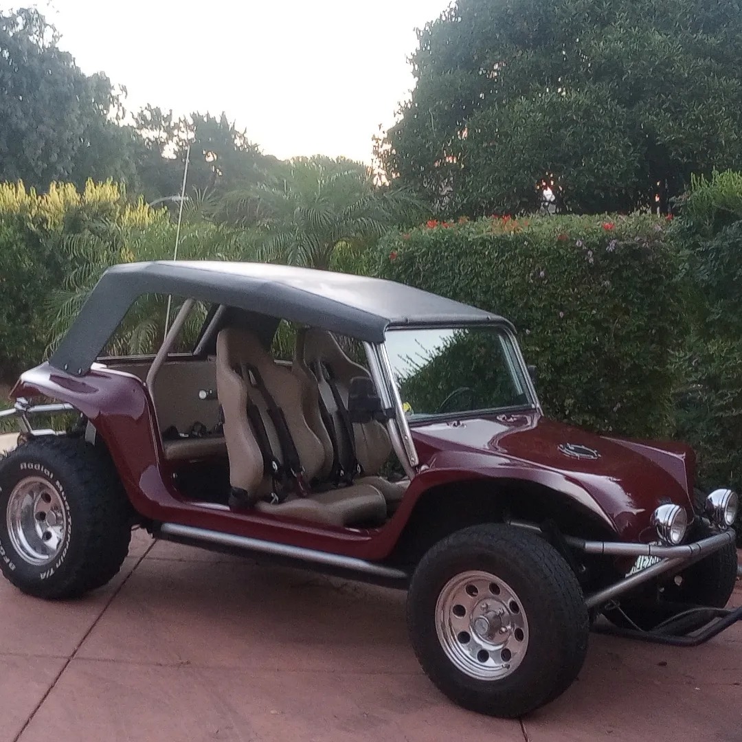
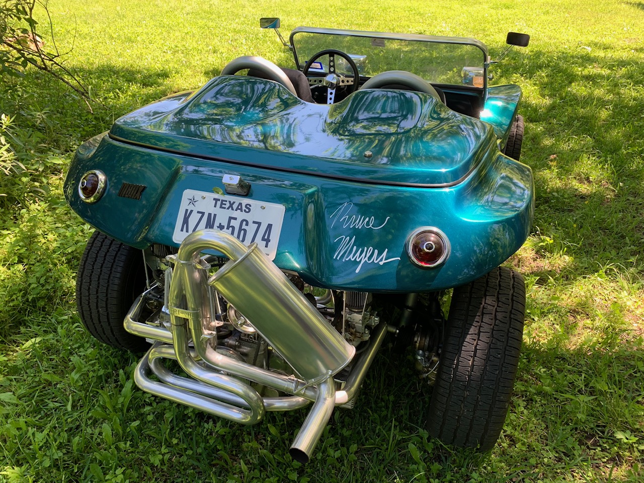
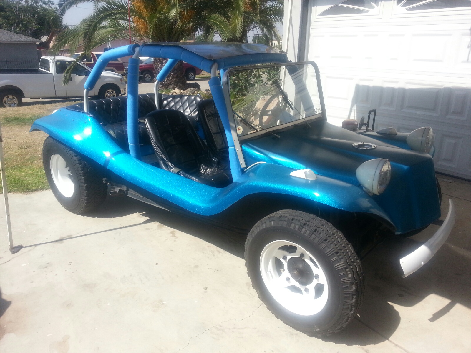
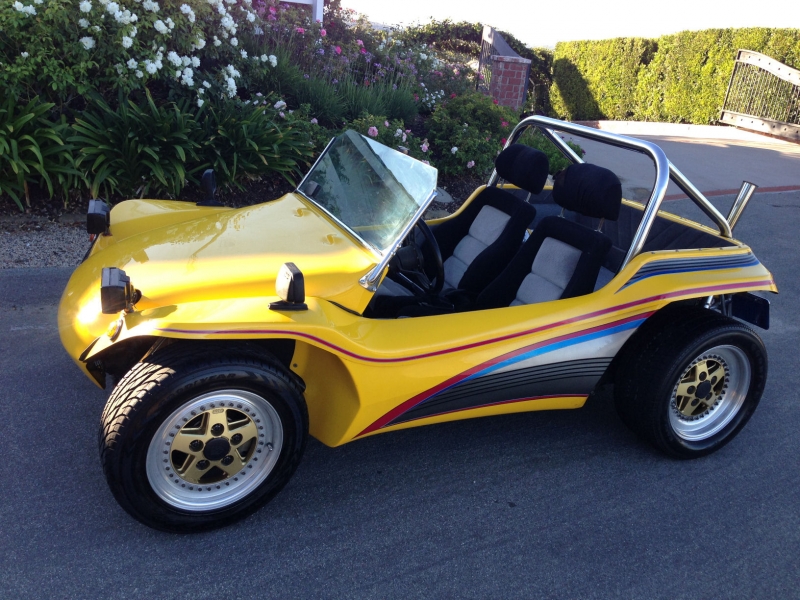
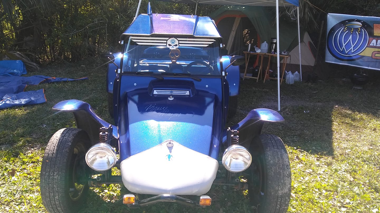
Read Articles →The story of the Meyers Manx — from Bruce Meyers' original creation to the modern revival.
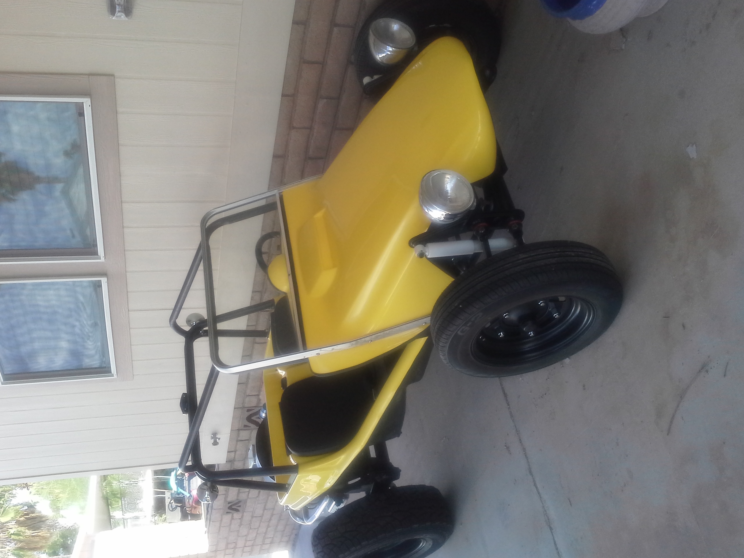
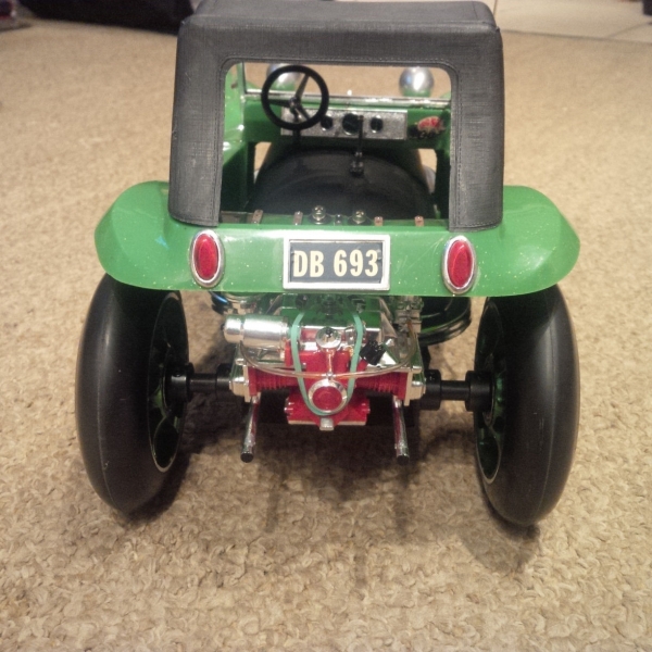
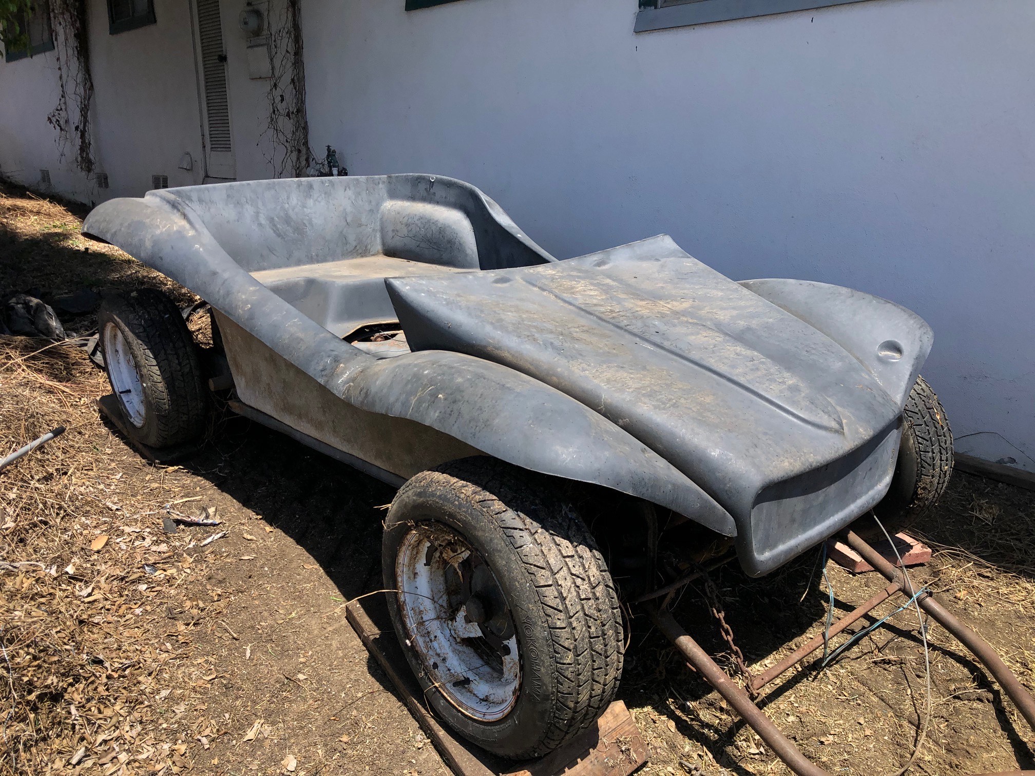
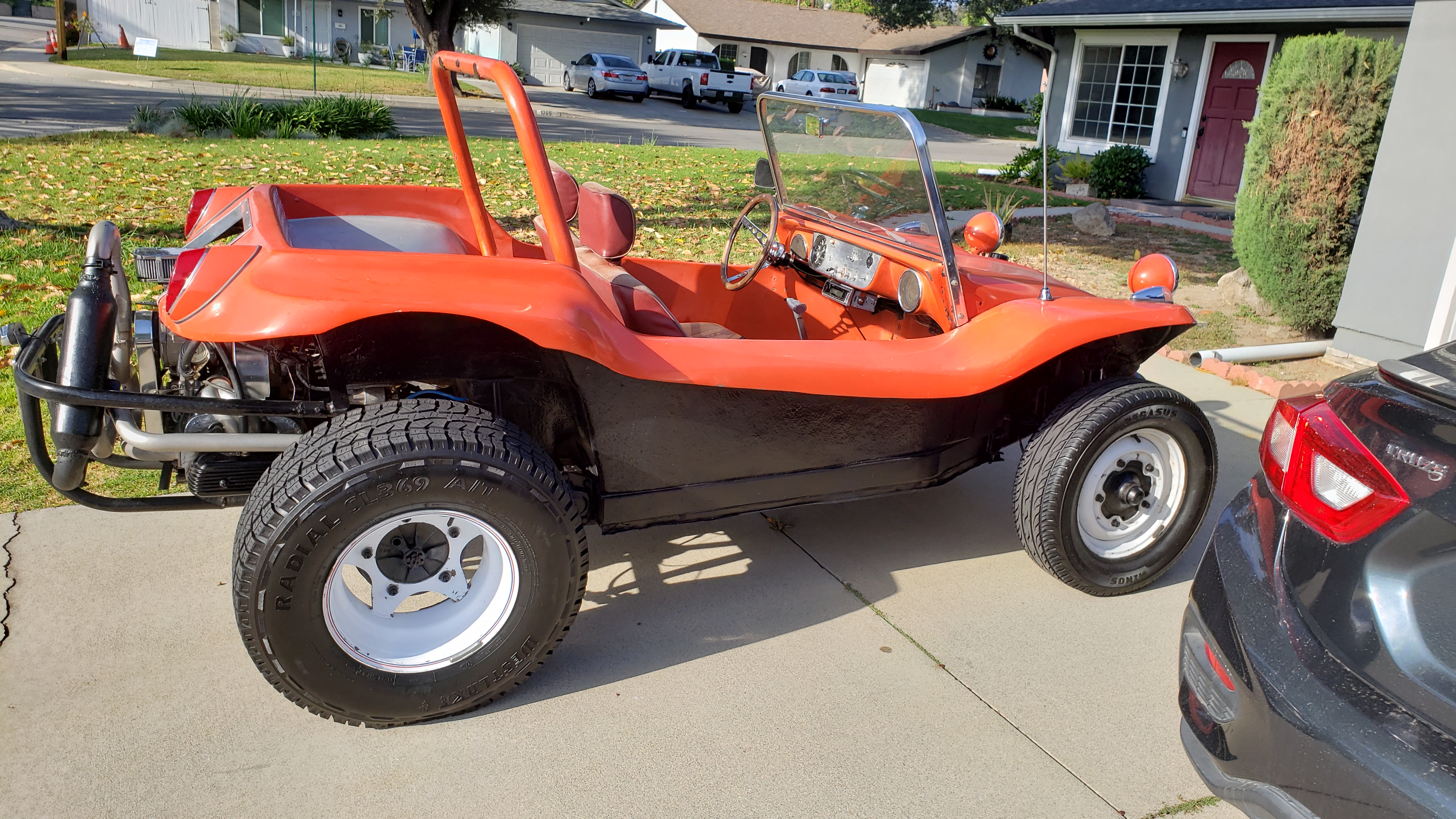
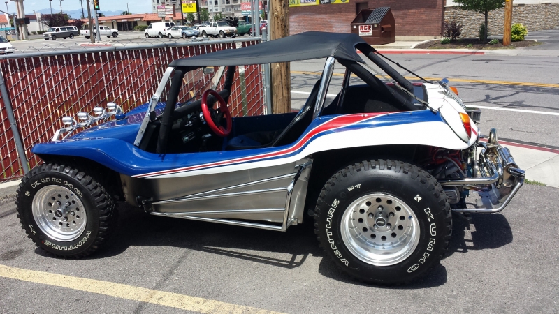
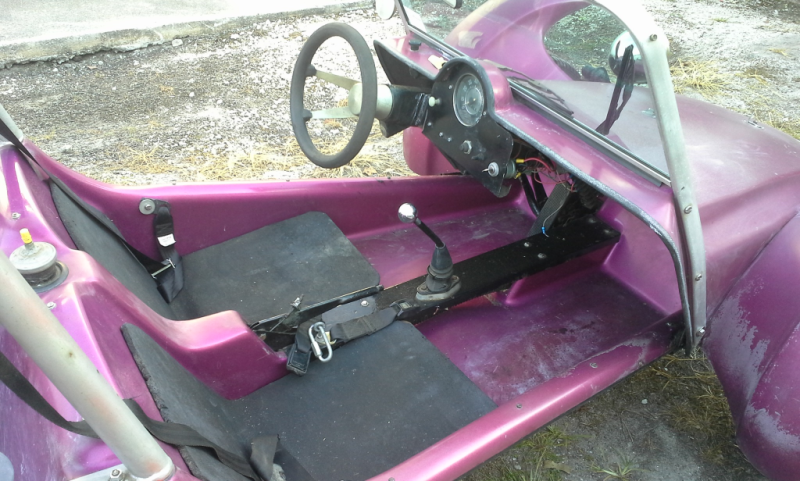
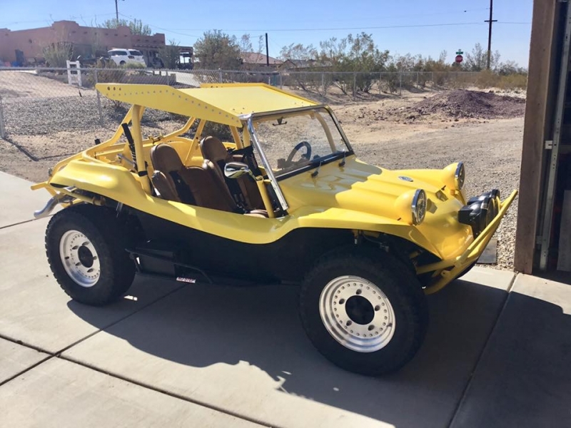
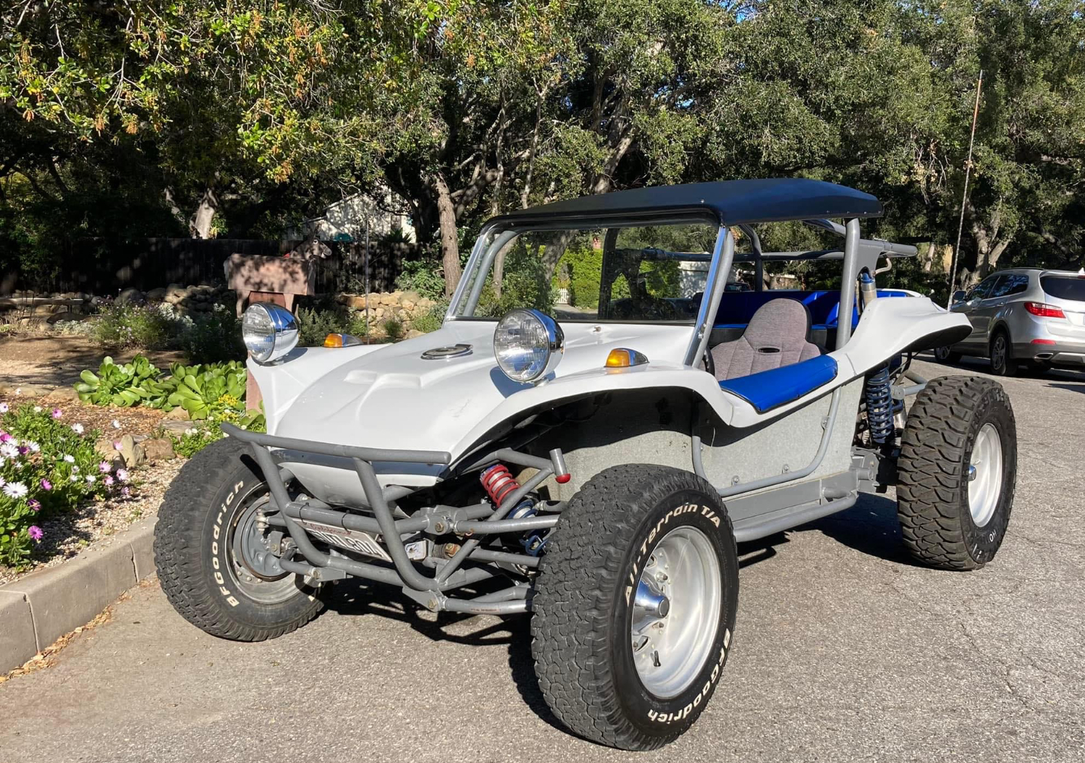
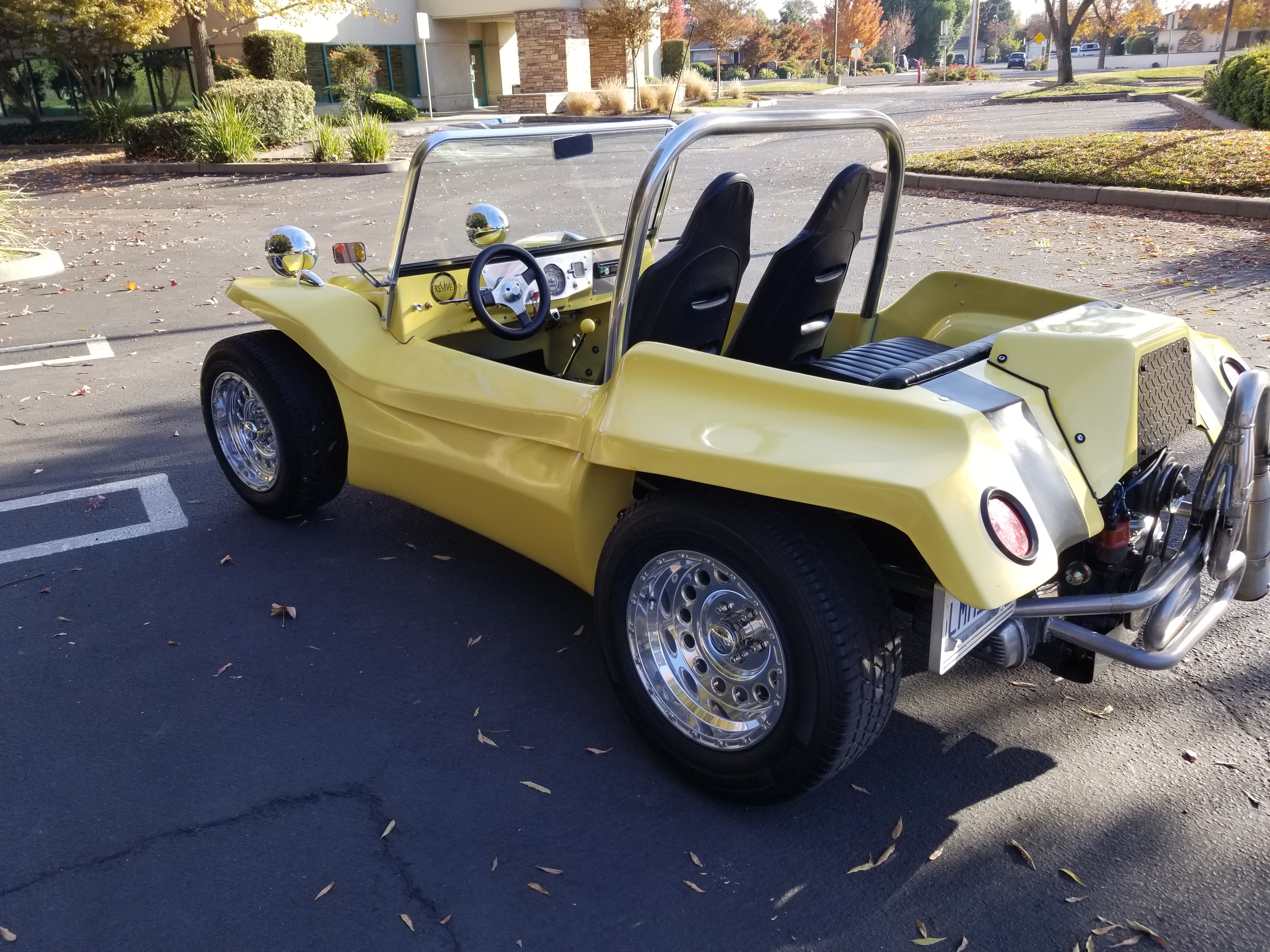
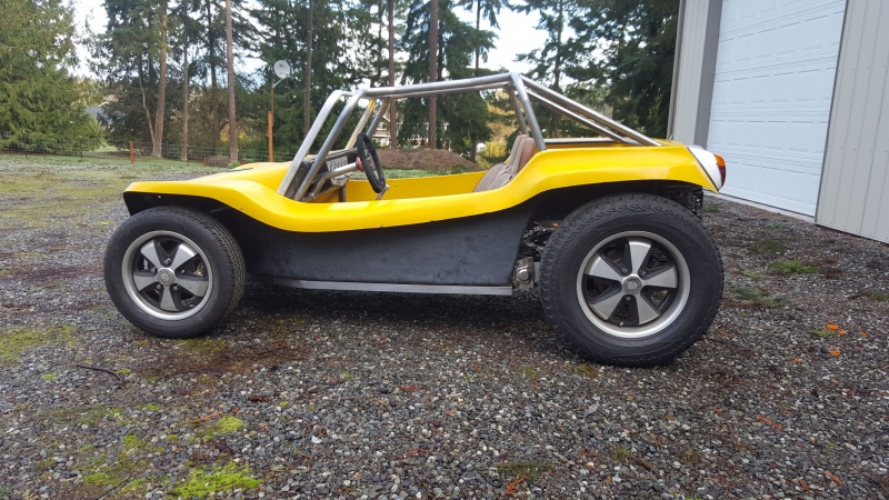
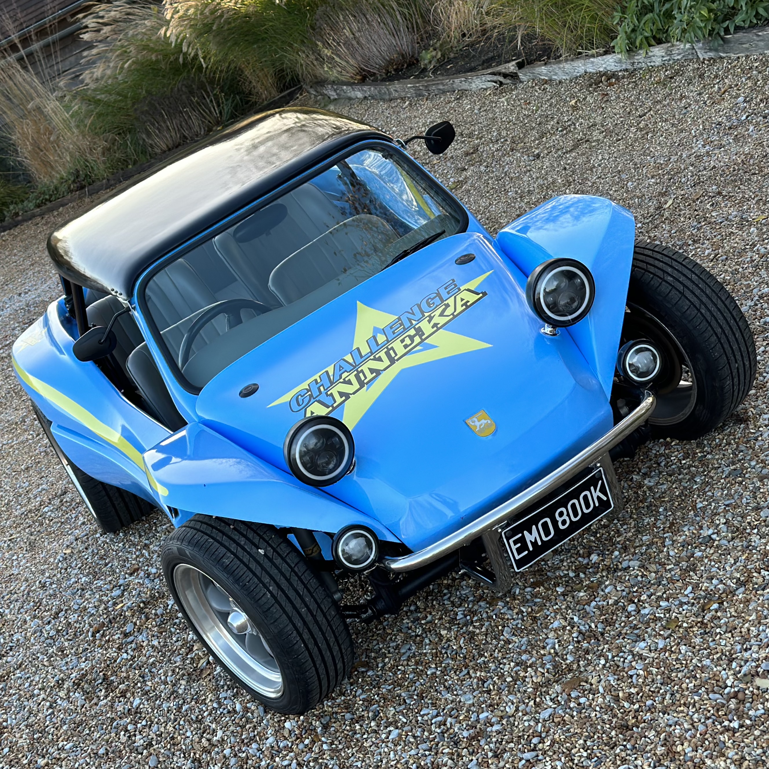
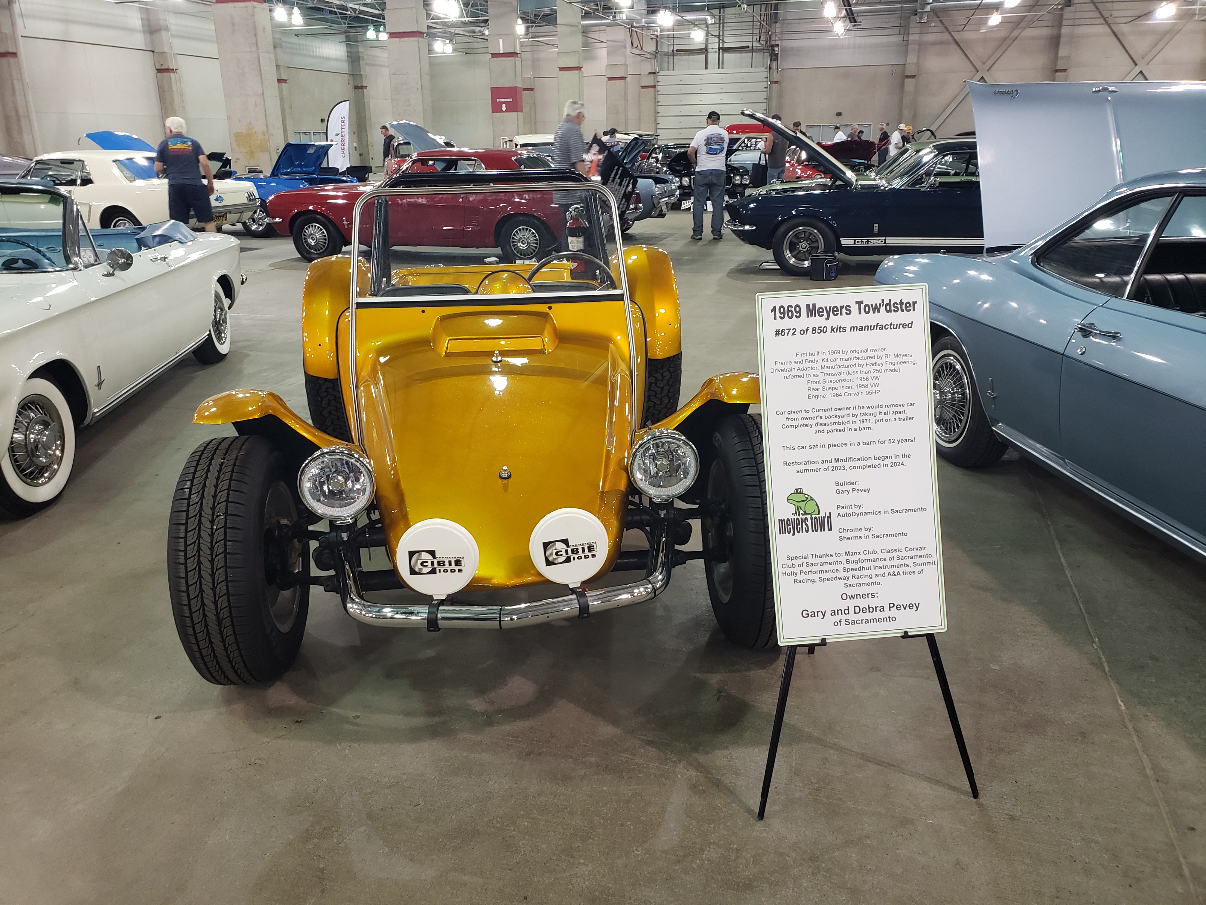
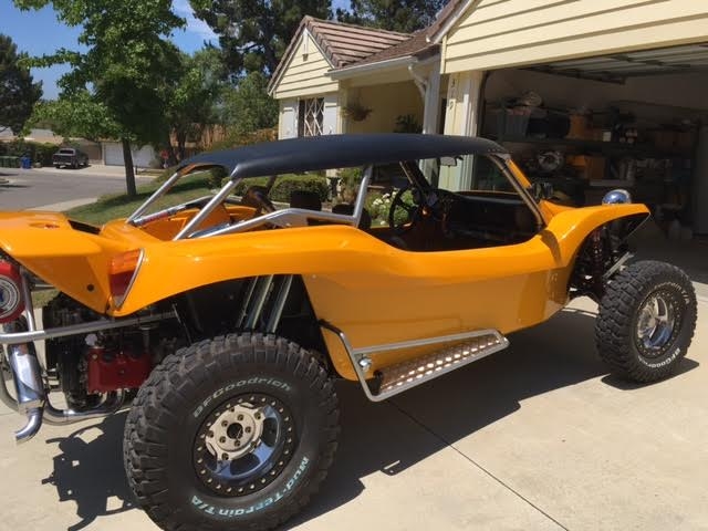
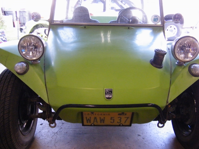
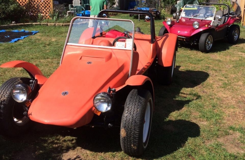
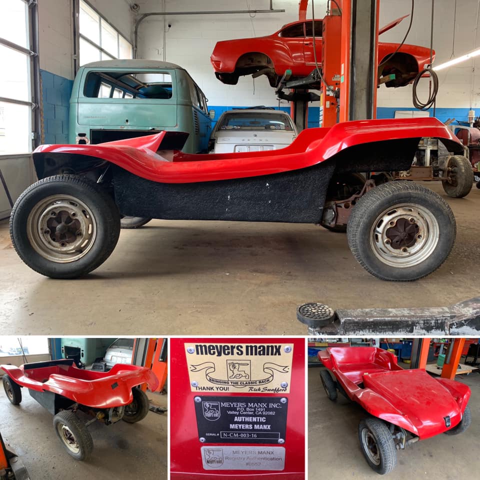
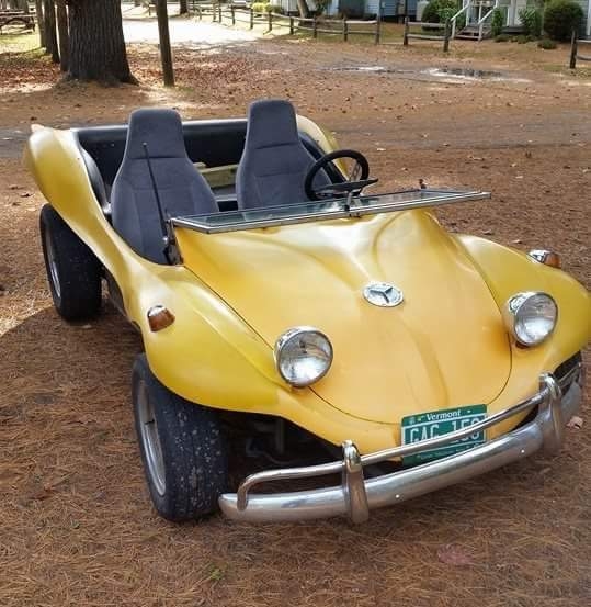
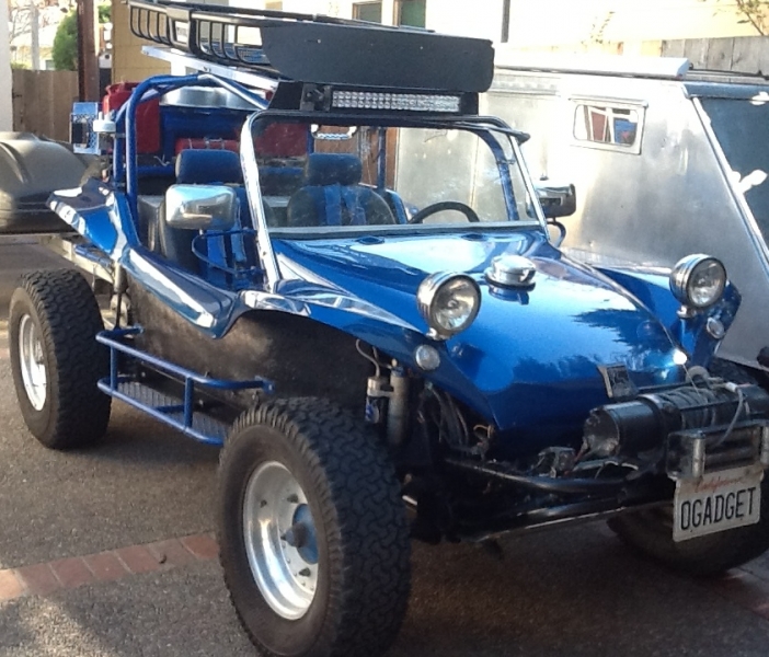
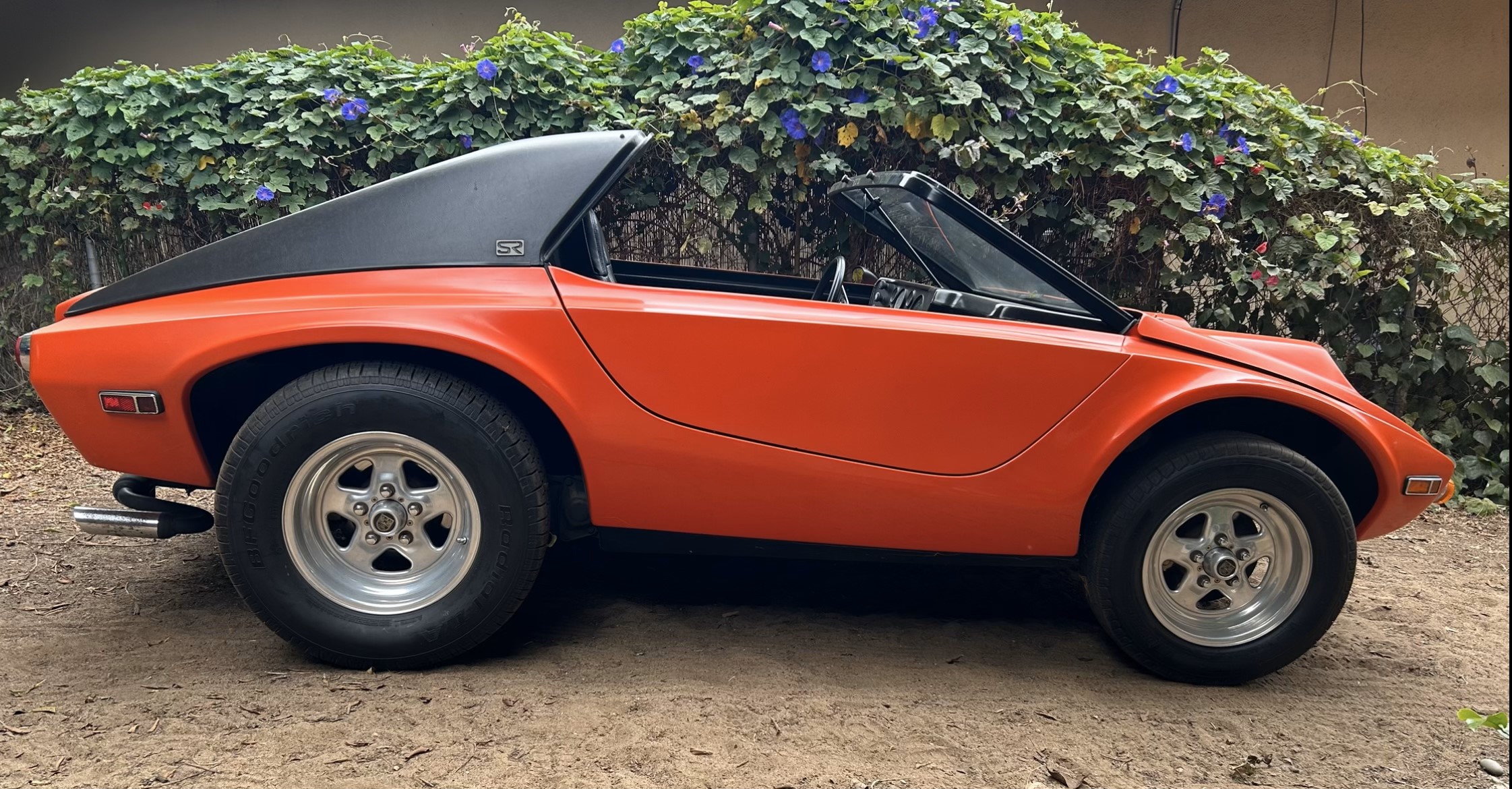
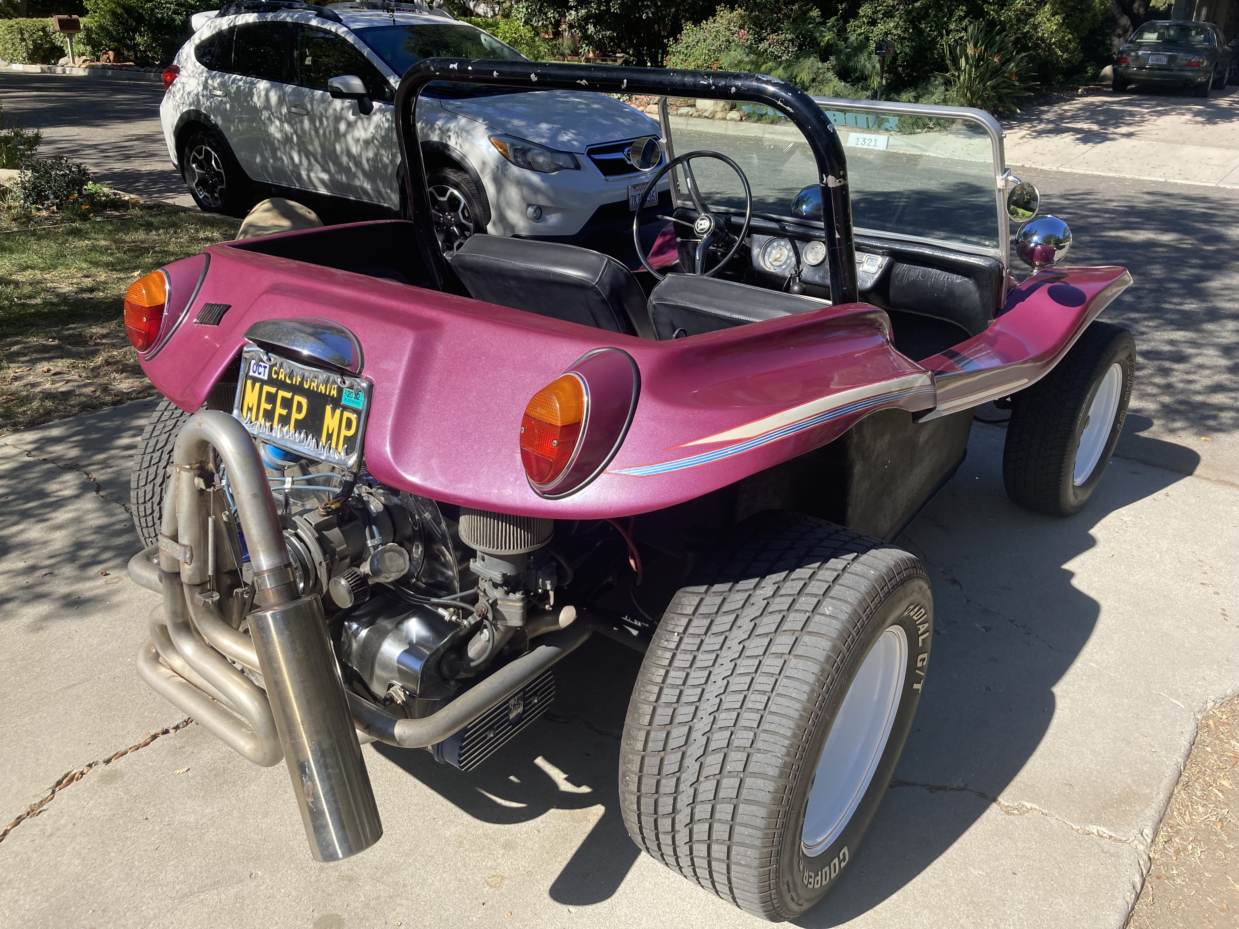
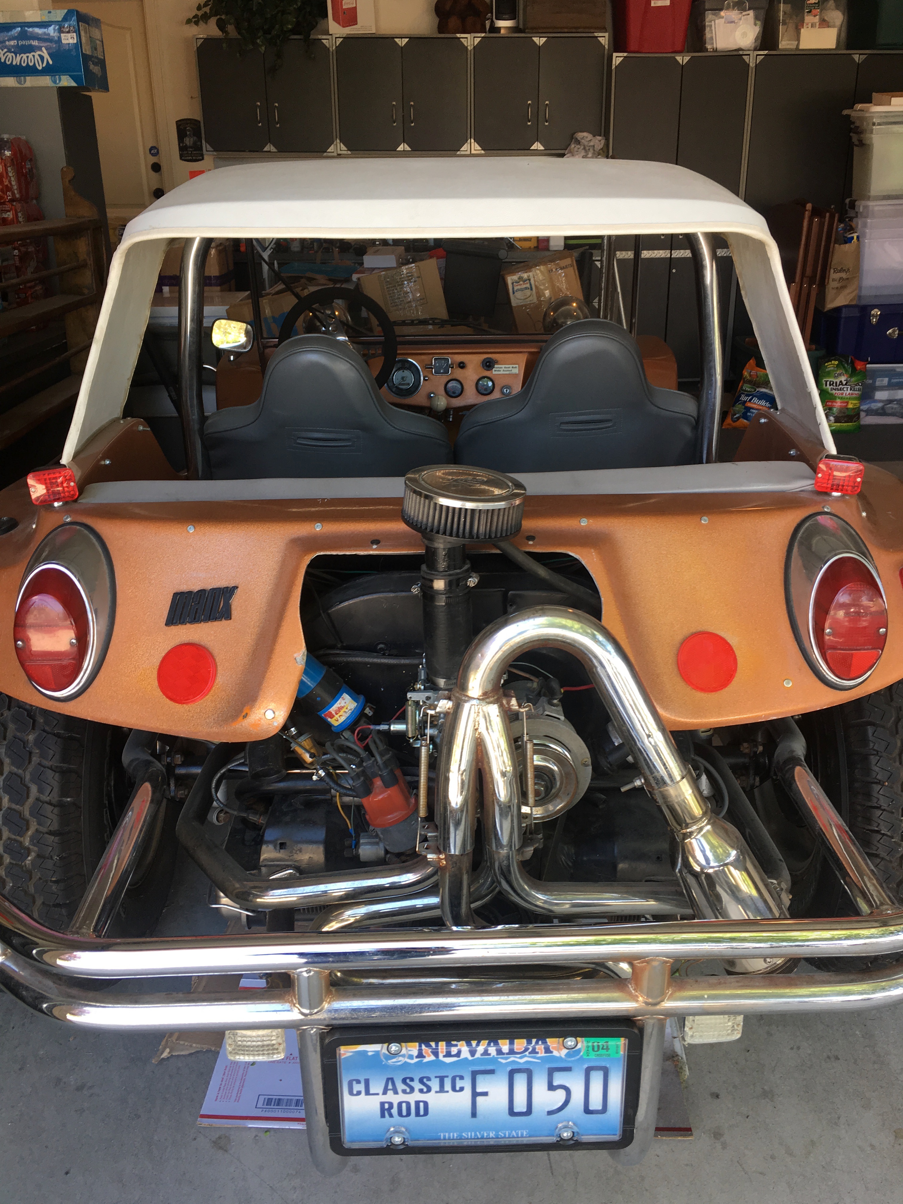
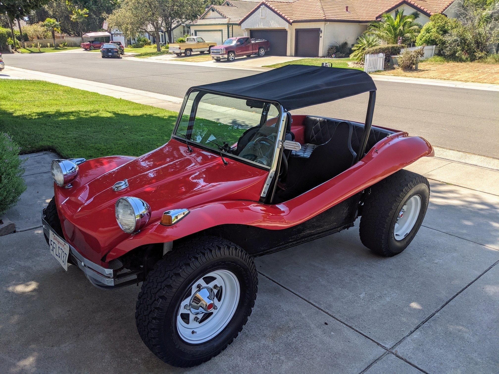
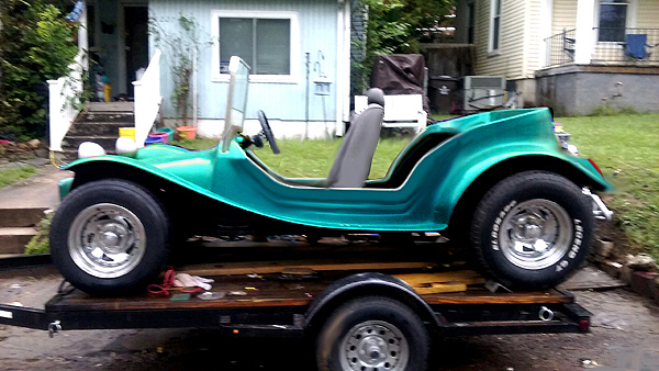
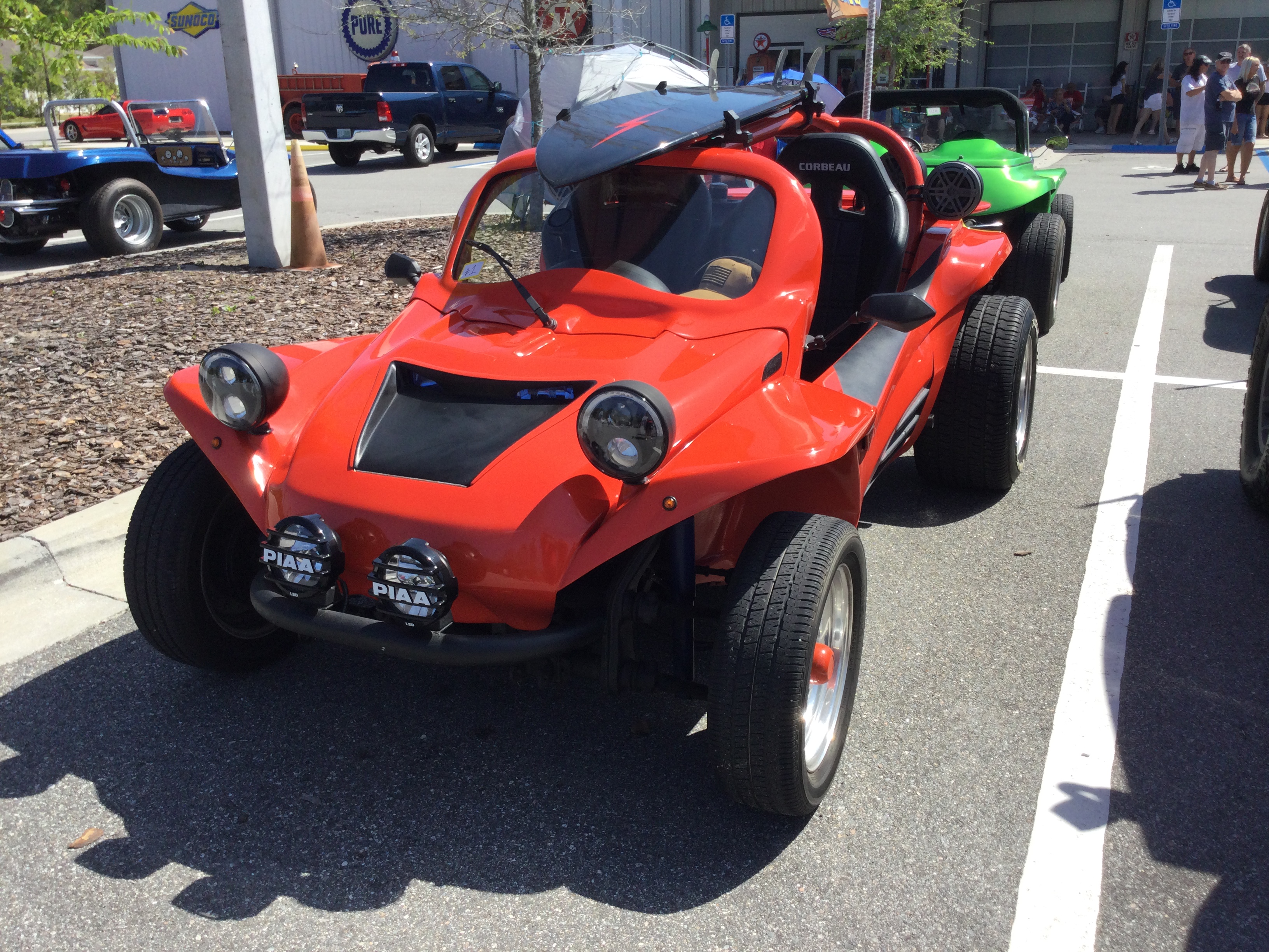
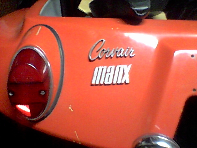
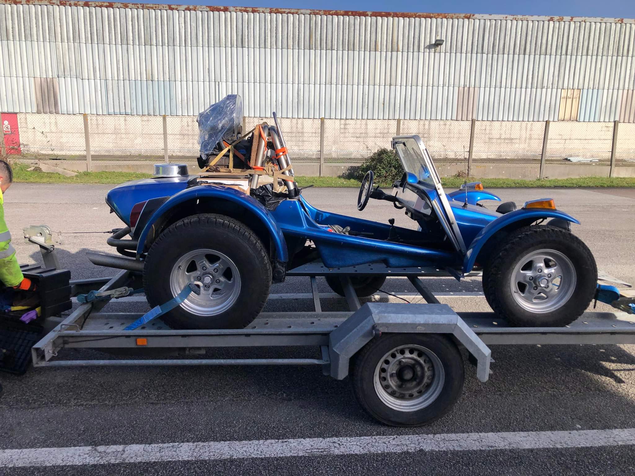
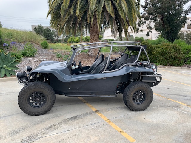
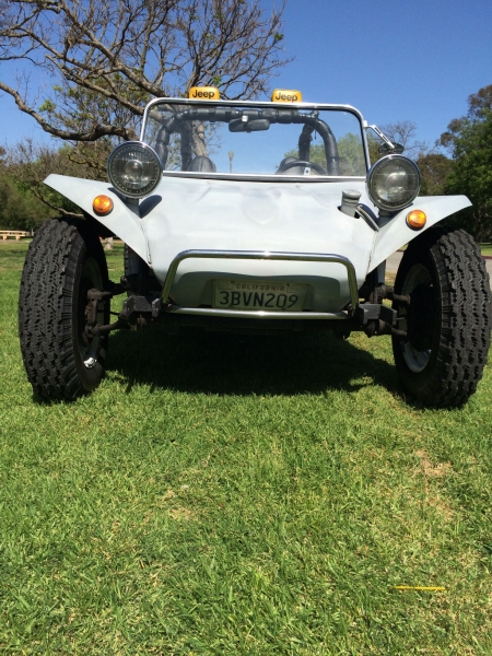
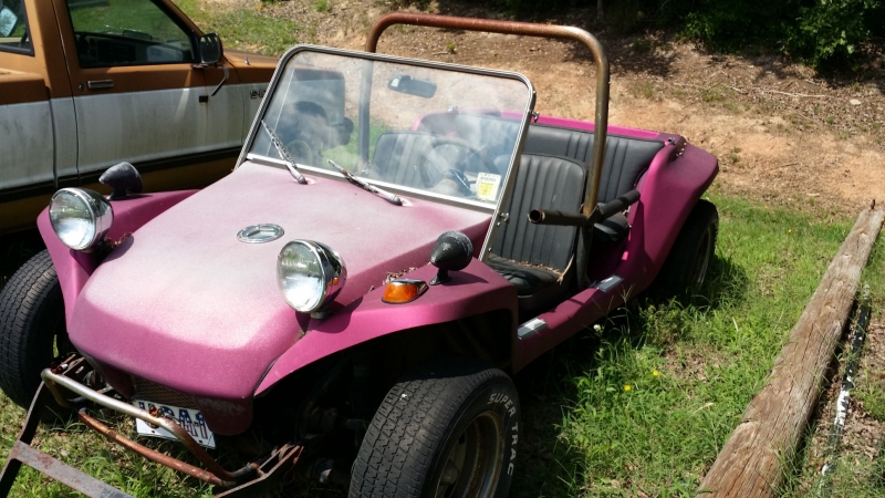
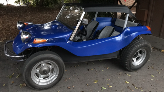
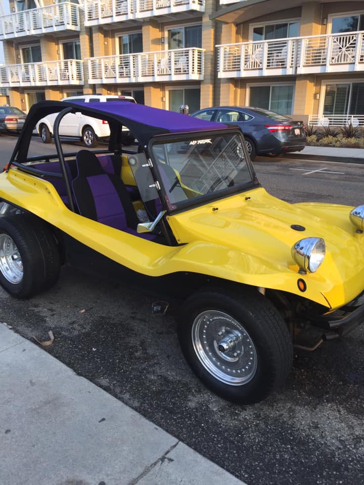
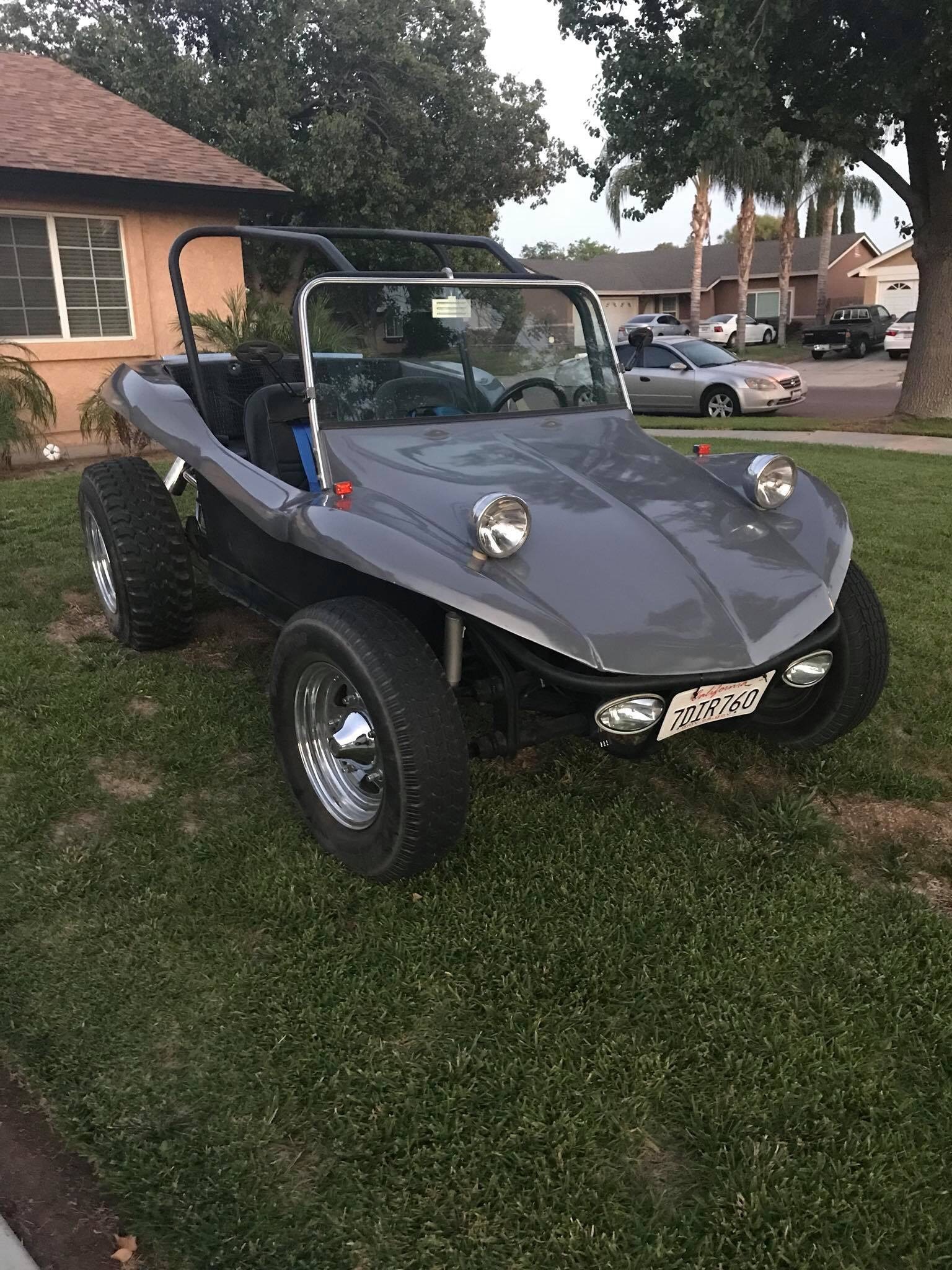
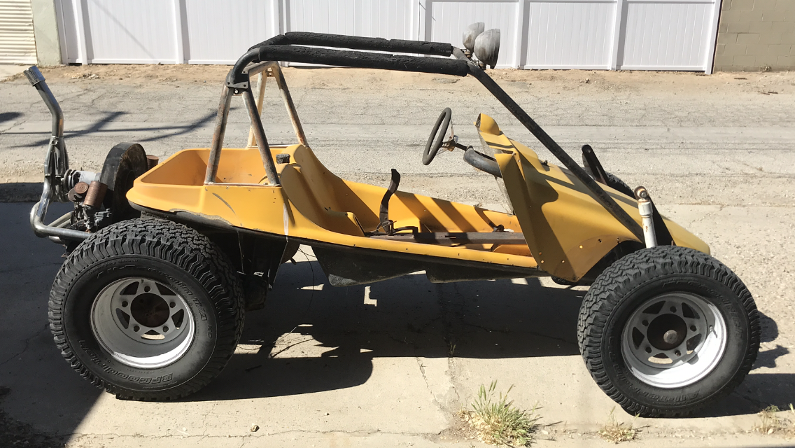
Read History →Not sure what clone you have? Use our guide to identify your buggy's maker and model.
ID Guide →The companies and individuals who support the Manx Club and its events.
View Sponsors →Shirts, hats, accessories and more — unique items for Manx enthusiasts. Managed by the Manx Club Store team at manxclubstore.com.
🛍 Visit the Store →Connect with thousands of Manx enthusiasts on Facebook and our community forum.


 Facebook Group
 Community Forum